To make a push-pull amplifier requires different type of output transformer.
I am aware of that. But I wonder if people have tried it, a simple two stage 807PP with local feedback and inputtransformer as a splitter, and what operating point they chose.
You can find your operating point in this detailed 807 datasheet: http://www.retrovox.com.au/STC807.pdf
I think it will work fine.
I think it will work fine.
To be honest I was thinking about using this front-end (designed by JC Morrison) for a 807PP amp with local feedback.
See also: new amp design @ Lab JC
See also: new amp design @ Lab JC
Attachments
The RH807 design depends on plate feedback current influencing the plate voltage of a relatively high Rp triode. Feedback would need to go to the 1st stage before the cathode follower. With the RH807 a CCS is not used on the driver plate, but certainly could be.
The cathode follower is not needed to drive an 807 unless you want A2 operation.
The cascode is cool but that driver balance pot is weird. It would need a little rework for local feedback.
Michael
The cathode follower is not needed to drive an 807 unless you want A2 operation.
The cascode is cool but that driver balance pot is weird. It would need a little rework for local feedback.
Michael
Here is an amp that intrigued me. Outputs are 807 precursors, Amp itself is a precursor to the Allen Wright PP1c. The cascoded LTP at the front is ideal for RH style feedback.
dave
Cascoded LTP in front of 6L6 derivatives with Schade style LFB is Miles' signature dish isn't it?
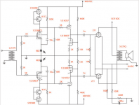
To be honest, I'm working on an 807pp amp myself.
60W AB2
That is, 400V on the anodes of 807, 300V (regulated) on the screens.
It uses fixed bias.
Front end is EF184 in a LTP. 350V B+ (regulated) and 175V (regulated) on screen.
Plate resistors are 27k. After the EF184's come the coupling capacitors that are connected to the source followers that connect directly to the 807's.
Some days ago, I connected the anodes of the 807's through a 220k resistor to the plates of the EF184's. It works fine! I didnt like the sound with smaller resistors, it was too 'sterile'.
Cascoded LTP in front of 6L6 derivatives with Schade style LFB is Miles' signature dish isn't it?
Not exactly. That was two different projects. The one that used 807s included local NFB (as recommended by Schade), 6SL7 LTP splitter with active tail load, and a 6J5 up front. It was the first hollow state design I did, and if I'd known just how good a cascode LTP was, then that's what I'd've done. It would definitely would have eliminated the need for a second gain stage.
The project that used the cascode LTP used 6BQ6GAs or 6BQ6GTBs, 6BQ7s cascoded to form an LTP with active tail load. That project didn't include local NFB since the 6BQ6s proved to not make so much higher order harmonics, and didn't need the extra help. That design was: 6BQ7 LTP --> 6FQ7 cathode follower grid drivers --> PP 6BQ6s. All that was needed was a little gNFB to clean up any residual pentode nastiness, and get the damping for the woofers.
I'm trying a similar scheme with my "No Light District" P-P amp. In my case, the input stage is a differential pair of matched jfets, each cascoded with 1/2 of a 12AU7. The outputs are 6CW5s. Pretty far afield from what's happening here. but at least it could serve as proof of principle for partial feedback P-P.
- Status
- This old topic is closed. If you want to reopen this topic, contact a moderator using the "Report Post" button.
- Home
- Amplifiers
- Tubes / Valves
- RH807 push pull ?