MOSFETs too...
Thanks
IRFP240 and IRFP9240.
IRF240 and IRFP9240???
Have you ever looked at those on a curve tracer? They are not even close. Sounds like something you must have read about in some magazine article or something.
They dont need to be close.
Feedback sorts out any differences.
I use them in my amps and get great results.
There are loads of amps arounbd using them, they are often pushed on here.
Last edited:
OK, then. I guess the answer to the original question is that it doesn't matter if the transistors are complementary because feedback will fix everything up.
Within reason.
The IRFP9240 was made to be a complement of the IRFP240.
Clearly P channel is much more difficult to make and some compromises had to be made.
They dont need to be close.
Feedback sorts out any differences.
The degree of 'correction' depends on what type of loop scheme is employed with that task. Just a plain ol' global fb loop can be overwhelmed by the high frequency distortion components that are related to the non-linear capacitances within a mosfet and may require extra compensation, chipping away at bandwidth......
 Feedback does not 'cancel' distortion but can shift it to a higher order of lesser magnitude. If a local loop is tasked with sorting out the differences and is short and fast, much faster than the global loop, the GFB loop will see a much more linear situation, which will make it a lot happier.
")
I actually use some of the most non-linear mosfets that could be used (cheap planer 'Q-fet' type switching FETs from Farichild), just out of curiosity to see how they could be made to work, but mostly because they have the same trans-conductance, which is the more important issue when using complementary source following mosfets. But with a very fast feedback/feedforward error amplified driver network those non-linear components do not make their way back to the 'global' loop.
The result is a very linear, low distortion amplifier.....with higher BW and SR, better SOA than bipolars, and a kick-a$s damping factor. This is something the typical single GFB loop LIN topology, designed for BJT's, just won't do if one simply substitutes these mosfets in for the BJT's.Within reason.
The IRFP9240 was made to be a complement of the IRFP240.
Clearly P channel is much more difficult to make and some compromises had to be made.
I guess we would have to define what is reasonable.
The two parts mentioned are not complementary and they were never designed to be complementary.
They are switching transistors. They were never designed to be used in linear applications. The similarity in part number only means that they have the same voltage and current rating when used as switches.
When you try to use them as linear amplifiers (which can be done but is not a very good idea), they will have not only the usual disparity in interelectrode capacitances due to the differing die size required by the differences in mobility between holes in the P-channel and electrons in the N-channel, but they also have vastly different transconductances.
Transistors with vastly different transconductances are not complementary, by definition.
That is an awesome list. Do we thank you for it?
Yep, I was keeping a list in word and I guess everyone was doing something similar. It's pretty much a list of transistors I have or I am interested in for future projects.
Greg, good list. However, Ic is wrongly shown in mA instead of Amps.
Thanks Samuel, I better fix that !
Another cut and paste error. I guess we would have to define what is reasonable.
The two parts mentioned are not complementary and they were never designed to be complementary.
They are switching transistors. They were never designed to be used in linear applications. The similarity in part number only means that they have the same voltage and current rating when used as switches.
When you try to use them as linear amplifiers (which can be done but is not a very good idea), they will have not only the usual disparity in interelectrode capacitances due to the differing die size required by the differences in mobility between holes in the P-channel and electrons in the N-channel, but they also have vastly different transconductances.
Transistors with vastly different transconductances are not complementary, by definition.
I agree, but there are pros and cons with trade-offs to any type of amplifying device. It is my experience that these transistors can and will work very well with certain error correction schemes and are much more suited to driving a reactive load, but even with EC it is still important that the devices you choose have a ~similar transconductance, and I agree this will most certainly be two devices of unequal capacitances and die size, and even different SOA ratings. They don't really have to have the same breakdown voltage or source resistor for that matter, but without some sort of EC, you will never really achieve the functionality of two vertical planer type matching complementary fets. It requires a few extra parts.
Forget Trench fets, they are not suited for operation in the 'linear' region due to thier physical construction, but the cell structure types are. However, I see lots of designs using these vertical fets with no local EC and low bias as if they are BJT's...... Not a very good idea.
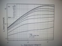
For the fets I have in my amp, the graph shows how much Id vs Vgs is dependent on Vds, and just how much the EC circuit must have to manipulate this terrible distortion.
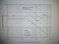
 Definately they are designed as switchers and without EC it would be nearly imposible to use these to linearly drive a non-linear speaker. But then for a cost of $0.69; Pd=120W minus 0.8W/C....20W @ 150 degrees .....in a TO-220 package. For the P-ch Pd=160W minus 1.06W/C, so 27W @ 150 degrees C. Since these are $1.60 each, it is good that the N-ch (of ~equal Gm) will fail first. Compare that, effectively ~10X Ft, and no secondary breakdown to a TO-220 BJT. Not even close.
Attachments
Last edited:
Rule #1 -- Don't ever rely on the data sheet.
Rule #2 -- See rule #1.
There are many reason not to use V-MOSFETs for audio amps:
a) They weren't designed for it, and aren't qualified for it.
b) They often show strange non-linearities in their response. Ask Nelson Pass about the IR P-channel parts. I discovered the problem back in 1992 when I was developing the first Ayre amp. I told Nelson about it when he sent me a letter wondering whether I had plagiarized his work in The Audio Amateur. In his reply he agreed that I hadn't but dismissed the possibility of any problems with the part. Since then he has acknowledged the problem.
c) The interelectrode capacitances are impossibly high. When normalized to transconductance, lateral parts have about 1/10 Cgd, which is what is important for a follower output stage.
d) The interelectrode capacitances are impossibly non-linear. They exhibit about 10x the variation that lateral parts do.
~~~~~~~~~~
If you want to be hard headed and insist on using perhaps the worst output devices available (just because they are cheap), why not pop some samples in your curve tracer. It's not hard to find pairs that are almost perfect complements, instead of just using IRFP9240 / IRFP240 because the part number seems similar. That pair has about a 2:1 difference in transconductance.
There are many reason not to use V-MOSFETs for audio amps:
.
Then why do my amplifiers sound so good ?
The proof of the pudding is in the eating.
They do have high capacitances but a good driver will overcome that.
Cin is usually counteracted because they are used in source follower configuration.
Ciss is mostly comprised of Cgs, which is effectively bootstraped in source follower. But the capacitances are highly non-linear which is another reason to use EC gate drive. The driver stage should be class A. For an output pair with total Ciss of 3nf, 30-40mA driver bias will be suitable. My amp sounds superb despite the non-linearity of those vertical fets and I would put it up against anything out there. I actually did not use these just because they are cheap. To build a balanced amp from +/-24V rails, higher Gm is needed and vertical fets are capable and fast enough to achieve the BW I am after.
Sure, I think if you don't know how to use them properly, and that includes the right choice of components, the few hundred mA bias required to counteract the drop in Gm at around crossover, proper local compensation to keep them stable, and linearization techniques. If these things are adhered to, you can make a really good amp from verticals. Otherwise I am in agreement with Mr. Hansen on the uses of vertical fets.
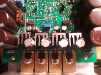
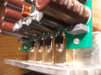
As a side note, my amp will clip at 120Wrms into 8R......from just 2 pair of TO-220 transistors. Not possible with BJT's, and I don't think they even make TO-220 laterals. I do admit these are directly mounted with no mica to a 1"/2"/0.5" piece of white brass to act as a heat spreader. The brass is then mounted using 4 mica pads to the heatsink bracket. The goal is to lower the overal thermal resistance from the die to the heatsink so I can drive them harder.
Sure, I think if you don't know how to use them properly, and that includes the right choice of components, the few hundred mA bias required to counteract the drop in Gm at around crossover, proper local compensation to keep them stable, and linearization techniques. If these things are adhered to, you can make a really good amp from verticals. Otherwise I am in agreement with Mr. Hansen on the uses of vertical fets.
As a side note, my amp will clip at 120Wrms into 8R......from just 2 pair of TO-220 transistors.
Not possible with BJT's, and I don't think they even make TO-220 laterals. I do admit these are directly mounted with no mica to a 1"/2"/0.5" piece of white brass to act as a heat spreader. The brass is then mounted using 4 mica pads to the heatsink bracket. The goal is to lower the overal thermal resistance from the die to the heatsink so I can drive them harder.Attachments
- Status
- This old topic is closed. If you want to reopen this topic, contact a moderator using the "Report Post" button.
- Home
- Amplifiers
- Solid State
- Power Amp Transistor Pairs