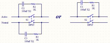
I'm building a chip-amp and thinking it can't hurt to use a C+R snubber over the power switch to reduce RF at turn-on. When using a DPST so both active and neutral are switched, is it necessary, pointless or bad practice to put in snubbers for both active and neutral sides (diagram attached)?
Attachments
Good questiion.
Both contacts are effectively in series - 'though either side of the Tx primary.
You are protecting against contact arcing/erosion as much as anything. Since at that level the contacts will have different switching times and bounce, it would be better to snub both.
Both contacts are effectively in series - 'though either side of the Tx primary.
You are protecting against contact arcing/erosion as much as anything. Since at that level the contacts will have different switching times and bounce, it would be better to snub both.
By a few orders of magnitude, put the snubber across the contact which opens first. If you can't tell which, then you need one for each.
I usually use a 2200pF Y1 type capacitor. This is sufficient to soften the remarkably fast switching edge (mechanical switches / arcs break much faster even than MOSFETs, so they generate lots of RFI). It probably still rings quite a bit at one frequency, but that frequency is much lower than the wideband RFI of an unsnubbed switch, so it causes a lot less interference.
You can, of course, add a resistor, making some guess at stray inductance, in order to properly estimate what resistance is required. The resistor will worsen performance somewhat (because it can allow the switch to arc), but will shorten the ringing, so if you have an application that cannot tolerate any narrowband interference (idunno what), it would be wise.
Tim
Thanks.By a few orders of magnitude, put the snubber across the contact which opens first. If you can't tell which, then you need one for each.
I usually use a 2200pF Y1 type capacitor. This is sufficient to soften the remarkably fast switching edge (mechanical switches / arcs break much faster even than MOSFETs, so they generate lots of RFI). It probably still rings quite a bit at one frequency, but that frequency is much lower than the wideband RFI of an unsnubbed switch, so it causes a lot less interference.
You can, of course, add a resistor, making some guess at stray inductance, in order to properly estimate what resistance is required. The resistor will worsen performance somewhat (because it can allow the switch to arc), but will shorten the ringing, so if you have an application that cannot tolerate any narrowband interference (idunno what), it would be wise.
Tim
Resistor in series with the capacitor (as shown in the attachement) or across active and neutral - I've seen resistors used across mains power and thought they were either part of a pi filter or something to do with passive power factor correction - I can find almost nothing on this on the internet (probably looking in the wrong places).
The audio amplifier application in question features a momentary self-mute on start-up (a capacitor pulling up the mute pin of the LM3886 for half a second) which may successfully suppress any switch EMI popping. In any case, protecting the switch contacts has got to be worthwhile.
From active to neutral? Um, both equipment and switch if possible.You could put one snubber on the transformer side of the switch. Are you aiming to protect the equipment or the switch?
") It's not a critical thing.
It's not a critical thing. Good questiion.
Both contacts are effectively in series - 'though either side of the Tx primary.
You are protecting against contact arcing/erosion as much as anything. Since at that level the contacts will have different switching times and bounce, it would be better to snub both.
Thanks. I was momentarily worried that any leakage from the capacitors would cause some current in the rest of the circuit but if that were the case, one snubber on one switch would be just as bad and I've seen plenty of those designs.If you're switching both sides of the line, you'll need two snubbers.
Thanks, everyone, for your comments!
Putting a single snubber on the transformer side of the switch puts the snubber right where the main inductance is, and automatically snubs whichever switch contact happens to open first without needing two snubbers. With two snubbers, one across each contact, one of them is probably unnecessary but you will never know which one.
A single snubber at the transformer ensures that there is no leakage current when the switch is open. The only thing it won't do is protect the switch from any spike arising from the inductance of a long mains lead, but in most cases this will be smaller than the leakage inductance of the transformer. I usually just put a mains-rated 5nF or 10nF capacitor from live to neutral after the switch - no resistor as the transformer copper losses provide enough damping in most cases.
A single snubber at the transformer ensures that there is no leakage current when the switch is open. The only thing it won't do is protect the switch from any spike arising from the inductance of a long mains lead, but in most cases this will be smaller than the leakage inductance of the transformer. I usually just put a mains-rated 5nF or 10nF capacitor from live to neutral after the switch - no resistor as the transformer copper losses provide enough damping in most cases.
Hello Random007
An important point is the voltage of the cap. It should be at least a 600 volt device and it’s possible that the CSA (Canadian Standards Association) even asks for a 1200 volt device when placed across a 120v AC line. The function of this cap is more useful as an arc suppressant that helps prolong the life of the switch. I believe that most people that has repaired amps must have seen (quite often in my case) amplifiers with power switches that have seized / welded contacts.
Cheers
Philip
Hello Random007
An important point is the voltage of the cap. It should be at least a 600 volt device and it’s possible that the CSA (Canadian Standards Association) even asks for a 1200 volt device when placed across a 120v AC line. The function of this cap is more useful as an arc suppressant that helps prolong the life of the switch. I believe that most people that has repaired amps must have seen (quite often in my case) amplifiers with power switches that have seized / welded contacts.
Cheers
Philip
I can do either an X2 (fails with open circuit at extreme conditions) or
a 640V capacitor (no guarantee what it will do at extreme conditions but it can take a pounding re voltage). If the high voltage cap is more likely to provide a graceful and sustainable spark suppressant + RFI, I'll pick that.
I'm still a bit ignorant as to (a quite possibly imaginary) capacitor leakage causing a very un-green constant power drain. I've run a SPICE simulation at it showed a 2mV constant supply beyond the switch when snubbers were installed and after that it just got crazy (I think I've discovered the solution to infinite worldwide electricity - a Marsbar - um, don't quote me just yet) and the computer wanted a rest and have a cool sponge on its forehead (no, really!) - I don't trust a simulation with 'ideal' components.
"I'm still a bit ignorant as to (a quite possibly imaginary) capacitor leakage causing a very un-green constant power drain........"
Any cap (OK - modern) rated for the voltage will have absolutely negligable leakage resistance. Electrolytics possible excluded, but they are not for use here.
So this is something NOT to worry about!
BTW - a larger (> ~1uF) cap will pass a measureable reactive current - just calculate its impedance at 50/60Hz. Again, we are not talking about that here.
Are you sure on the X2 failure mode there? It is dependent on the material/construction. I strongly warn against using non- X or Y cap for this application as it will not have the spike survivability.
Y is the most severe rated cap, therefore I would use a Y rated cap for the switch as you don't want a failure to leave the device powered unknowingly. I use metallised paper.
Y is the most severe rated cap, therefore I would use a Y rated cap for the switch as you don't want a failure to leave the device powered unknowingly. I use metallised paper.
Last edited:
These snubbers WILL (with proper R and C values) protect the switch, but will do little for the real problem, the "kickback" and ringing of the transformer's primary winding when a voltage as high as 160V is suddenly removed. Power transformers have a relatively large stray inductance, and the disconnection of the switch at any time other than the current being at zero crossing will cause a substantial voltage to appear across the primary, which then arcs across the switch contacts.
Snubbers with "proper" R and C values across the switches will indeed protect them, but will radiate the spike through the power line to be picked up by and interfere with other equipment.
The proper solution is to put a snubber across the primary, and use values that substantially reduce the spike. I just ran an LTSpice sim, with a SWAG at primary stray inductance of 1mH, primary DCR of 10 ohms, stray capacitance of 15pf (perhaps not significant here, but may make a difference without the snubber). I use two voltage sources and the "switch" thing to switch the voltage on and off at the peak, about 169V with 120VAC RMS input. With a C and R of .1uF and 1000 ohms the spike is 10.5kV. Fiddling around a bit, 4uF and a 10 ohms gives an overshoot peak of 15V. These may work with the transformer you have, but put in its DCR and stray inductance to make sure.
For best results make primary leads as short as possible, and put the snubber R and C right there at the lead connections, with leads as short as practical.
The LTSpice simulation file is attached if I did it right. A .txt extension was added because the attach thing didn't like .asc, so rename to remove the .txt extension to load into LTSpice.
With this, any voltage generated across the switch will be from the relatively small stray inductance of the chassis wiring and the power cord, which would have much less effect if any on other equipment, and shouldn't reduce the life of the switch.
I was inspired by a recent (or maybe not, there's a lot of good old thread here) thread on using LTSpice on the secondary side of the transformer to show how putting capacitors across power supply diodes snubs high voltage ringing, and thus 50/60Hz noise in the audio device the power supply powers. Some good knowledge and investigative techniques do wonders.
One more thought, this thing presumes a nice clean 60Hz line input. A large power line spike from an industrial motor turned off or a lightning strike could well blow out the resistor in the snubber. Making this thing absolutely bulletproof is left as an exercise for the reader.
Attachments
The proper solution is to put a snubber across the primary, and use values that substantially reduce the spike.
Actually, the best position is across the contacts. Putting it across only the transformer neglects stray wiring inductance, from transformer to switch to power line. (And the stray inductance from transformer to switch *will* ring noticably, too!)
The most intuitive solution, put the snubber at the switch. When the switch opens, no other point in the circuit has higher d/dt. Put the snubber at the highest d/dt. This works for all switching applications: transistors, tubes, switches, relays, etc. In some cases, it's only a convienience (like here); in other cases, it is literally the difference between proper operation and instantaneous destruction! (IGBTs switching >100A are not appreciative of improperly snubbed circuits!)
In my earlier post, I recommended a Y1 type cap, which is rated for line-to-ground surges. X1/Y2 type are rated for line-to-line, which is also suitable here, though Y1 types are usually ceramic, and therefore will have somewhat better performance over 10MHz. In both cases, these capacitors usually come in 250VAC nominal ratings, but are specified for peaks of several kV.
If you use a fairly large capacitor (like 0.1uF), you will draw noticable current, but it is mostly reactive current, so the power meter doesn't see it. Such a large value isn't good practice though.
Interesting factoid: if you use a fairly large cap (like 0.1uF) into an unloaded transformer, the primary voltage will read higher than line voltage. This is simply because it's acting like a series resonant circuit. This is not dangerous (though it can result in unexpected voltages).
Tim
- Status
- This old topic is closed. If you want to reopen this topic, contact a moderator using the "Report Post" button.
- Home
- Amplifiers
- Power Supplies
- Snubbing power switch properly