Sansui 1000A OPT replacements

Hello,
I just purchased a Sansui 1000A to rebuild/restore. This amp/receiver is missing one of the Sansui Output Transformers, and the other one is out of the chassis and impedance readings indicate shorts, so I am looking to replace both of them in the rebuild. I cannot find any good used ones or Hashimoto replacements, so I am looking at the Hammond 1650 series. From what I can tell the 7591 output tubes feed the transformers in a push/pull circuit. The original transformers are rated at 6600ohms P-P, with and 8 and 16ohm output.
Will one of the Hammond 1650 series work? Which one is the best choice as a replacement? The HA or the PA?
Or, do you have another suggestion?
Thank you in advance for the advice

Regards,
Kevin

Attachments

  • Hammond.jpg
    Hammond.jpg
    189.1 KB · Views: 252

Interesting article about audio-oriented SMPS

This one specifically deals with a LLC, but many of the general considerations also apply to other topologies.

https://www.edn.com/power-tips-103-llc-design-considerations-for-audio-amplifiers/

As the requirements of an audio-oriented switching supply seem to be widely misunderstood in this forum, this piece is a must-read for anyone trying to design such a supply from scratch, or to reuse a "normal" switcher for audio applications

This driver JBL 12" 12PW will work as subwoofer for a HT?

The specs that i found was

Sensitivity (dB): 94
Frequency Response (Hz): 40Hz - 5200Hz
Resonance Frequency (Hz): 46
Thielle Small Parameters:
BI: 12.73
Qms: 8,900
Qts: 0.510
Sd: 0.051m2
Vases: 87,7L
Vd: 255cm3
Xmax: 5

Maybe can use 2 of them, want to use it for HT with linearray as main speakers.

I can get 2 JBL for half the price of Faital Pro 12fh510 or Faital Pro 12FH500

Mu follower with frequency dependent CCS gain

I got another one of my probably dumb ideas, haven't seen anyone else try or talk about it so here goes:

Can I mod a standard mu follower such that:
  • more current gain on the low end
  • more pure ccs on the top end

by adding kind of a crossover in the amp like in the schematic? The inductor and cap in the example are calculated to both equal 0.6 ohm @ 1000 hz.

Attachments

  • standard.png
    standard.png
    10.7 KB · Views: 181
  • strange.png
    strange.png
    13.4 KB · Views: 170

3a5 output stage advice

Hi all,

I'm looking for a little advice on the implementation of a cheap 3a5 board commonly available on Aliexpress. The pics below show the board which I guess many of you have seen, and I've included the schematic as well. I've hooked it up on the output of a DAC, and it performs "fine" but as you'd expect there is hum etc.

Not having any experience with DHT valves, in particular, I'd like some advice on heater wiring. So you can wire the heater in parallel or series, either 1.4/2.8V and 110/220mA current draw. There is cathode bias on this board, so I can't see how I can do what others advise in some other 3a5 threads, and connect the DC 1.4v across pins 1+7 and 4 and connect one end to ground. Obviously I'm missing something here, but having read around a bit I'm not any wiser!!

Is it as simple as leaving the heater supply floating? Any other advice to play with this thing?

Many thanks in advance for any help.

Attachments

  • 3a5board.png
    3a5board.png
    668.2 KB · Views: 721
  • 3a5.png
    3a5.png
    374.3 KB · Views: 1,289
  • 3a5 datasheet.png
    3a5 datasheet.png
    355.8 KB · Views: 705

Inexpensive, small form factor surround processor?

I'm looking for a small form-factor surround processor (something approx. the size of an 8-port ethernet switch or a cable modem) that will accept a SPDIF input and decode (at least) AC3/DTS, outputting 5.1 (or 7.1) line-level analog. Ideally, it would have a remote for master volume control. If it can decode Dolby TrueHD and DTS-HD Master Audio, that'd be even better though it would need an HDMI input to do so.

I suspect that something like this doesn't exist. If not, I'd appreciate creative input on cobbling something together.

One idea I had is a NUC PC running Linux with a 7.1 USB sound card. But what software do I use to decode the AC3/DTS?

TU-8500 - Muses02

I've been trying out some Muse02 in my TU-8500 after upgrading to an AT-ART9XA a few weeks ago from an ART-7. Previously I was using the Muse01 with the ART-7.

8UHspez


So right off the bat I'll say that the Muse02 are much better for my current setup because I'm using a moving coil cartridge.

I used the Muse01 for a week with the new AT-ART9XA before switching over to the Muse02. And they sound exactly the same as the Muse0. That is probably because they are more or less the same. But with one major difference! The Muse01 are J-Fet input and the Muse02 are Bi-polar input.

Because of this the Muse02 are far better suited for Moving Coil, they provide a bit more gain over the Muse01. The biasing current is lower too, so noise performance is much better over the latter.

If you have a Moving Magnet you could play around with both in your TU-8500, but you would probably be better off with the Muse01, those are better suited for high impedance sources like Moving Magnet cartridges.

Anyways, the Muse opamp truly shine in the TU-8500! Highly recommend them if your looking for a premium upgrade!

My next step from here is to make a hybrid Muse02/Muse01 opamp. I'll be using the Muse02 in the input stage and the Muse01 in the gain stage.

Would Someone Do

A quick and dirty XO simulation of my drivers? No measuring capability or understanding of XO software here. I'm using SB16PFCR25-4 in a tall 24 liter BR crossing to Fostex ff85wk in a small uOnken set on top ala Kef 105.
SB Acoustics SB16PFCR25-4 6" Paper Cone Woofer - 4 ohm- ROUND
Fostex FF85WK 3" Full Range
I'd like to stay passive and use my tube amplifiers/rebuilt Heathkit W3M.
Thanks so much.

6F12P and 6P43P push pull triode amp

Just kanged together another amp. This one uses 6F12P for gain and phase splitting duty, and 6P43P in triode connection.

It also uses toroidal power transformers as OPTs like all of my other designs... The total build price is less than $300CAD with a chassis etc.

The output stage is biased at 270V/56ma which slightly exceeds the dissipation, but like George of Tubelab I'm willing to push the tubes a little harder than specified.

Thoughs?

EDIT: Don't use one OPT, use two... Search for "interleaved toroidal
921505d1613151218-stupendous-6p1p-4pp-amplifier-opt-wiring-diagram-png

Attachments

  • 6P43P-PP-TRIODE-TL783.png
    6P43P-PP-TRIODE-TL783.png
    107.9 KB · Views: 1,735

Constant directivity at home is it possible ?

Can professional CD solutions be used in a home space?
It would seem that if you look at Keele's design, but why did no one build a similar design here at DiyAudio?


Don Keele's CBT (Constant Beamwidth Transducer) Page

Constant Directivity: A New Approach | PreSonus

Constant directivity loudspeaker designs

Attachments

  • cdl_4-boxes.png
    cdl_4-boxes.png
    271.6 KB · Views: 480
  • keele_cbt-a.jpg
    keele_cbt-a.jpg
    73.7 KB · Views: 501

El Cheapo testing

I'm currently testing the first channel of my El Cheapo.

Attached are the first test results using REW. I _think_ my frequency response is quite ok, but my THD(+N) is quite high. Is that correct?

I would love to provide more info, but my level of experience is holding me back. I have no idea what I should tell you... 😕 One thing that struck me is that I can lower the THD quite a bit at the expense of noise by lowering the input signal.

Does anyone have some advice? Some handy documentation?

Thanks in advance.

Attachments

  • frequencyResponse.png
    frequencyResponse.png
    34.7 KB · Views: 709
  • distortion.png
    distortion.png
    51.5 KB · Views: 714

Alpine MRV-F300 won't turn off most of the time.

Alpine MRV-F300 turns on whevever a door is opened?

This is an edited post - I wired up an Alpine MRV-F300. I used the speaker-level inputs. My HU doesn't have a remote-lead. The manual says that if using the speaker level inputs, you don't need the remote-lead, except in some cases.


My problem is that whenever I open the door, the amp comes on, even if the HU isn't on yet. Does anyone have an idea why or what to check for?


Thanks.

FS: AKG K240 Sextett Cardan 4-600 ohm headphones (Made in Austria)

I am selling my AKG K240 Sextett Cardan headphones. It's in a very-very nice condition, shipped in its original box and with its original documentation. There are signs of usage on the box, but it's still in good shape.
Item is located in Budapest (Hungary), but I am happy to ship it to anywhere in the World.
Headphone has been fitted with a jack connector.

Asking price is EUR 110 plus shipping.

jdPxAkx.jpg

UPMJaOj.jpg

yM81MsR.jpg

ToMsbuf.jpg

InN7k5W.jpg

K3ACdfu.jpg

diy ethernet cable

Hello,
I do believe in differences between cables and even between ethernet cables there are differences i guess.
I think there must be differences between connectors too. I like the way the Telegartner and Keystone are constructed.
What would be a nice ethernet cable '' soundwize '' to make my own cables between Roon Nucleus, modem and Etherregen switch.
Greetings, eduard

Discrete opamp instability help needed

I'm playing around with a circuit idea for a poweramp front-end, but thought I'd try examining it as an opamp to understand it better. And now I'm stuck trying to solve an instability at 11 MHz when operated as a unity lo-pass inverter. I'm at a loss. I can see how changing the values of R4 and R22 change the ring, but I don't see how to squelch it. It seems to be acting as a short from the VAS down to the p-jfet on the input. In a way, if I avoid letting this freq into the circuit it won't ring, so maybe there really isn't a problem here... or not.

Screenshot from 2021-08-01 15-28-17.png

View attachment test inverter HV.asc
View attachment test 60x HV.asc
View attachment fetopamp2_hv.asc
View attachment fetopamp2_HV.asy.txt

advice on choosing electrical power supply bench

Hello everybody.
I would like to ask you for advice on choosing a hobby laboratory power supply with the best value for money.
it will be used for general electronics: TTL, CMOS integrated circuits, dual powered operational amplifiers (OPAMP), thyristors, optocouplers, relays etc.
I am oriented more on linear but what do you think?.
Maximum Badget € 100.
What do you think are the characteristics to take into account before choosing?.
bye thank you

T/S Parameter Sanity Check

Hey Guys! Upfront: I tried posting this on avforums, as i did another question before that, but since i am not getting an answer there, i thought i'll try it here. Seems a more suiting place anyway =)

Last Weekend is was finally able to put my DATS V3 to work. Unfortunately, the way to get there was rough, to say it nicely. After my diy-testbox was too big according to the DATS - 47liters, and not rethinking that error even after reducing the volume by almost 10liters, i threw the box in the garbage and did weight based Vas measurements. The two subs have both seen service in a dual ~30l (for each) sealed box in car-audio, were then put in the basement for quite some years, and were now pulled out to give them a new life.

Here are my measurements along with the manufacturer ones. It seems weird to me that they are that far apart from each other.

Since i want to built separate Enclosures for them,would a recommendation for one of those change in respect of the measurements?

Intended use is Home-Theater and Music at Home.
I am currently planing a vented enclosure, but i am also struggling with stuff like "WinISD gives me an 10x10 Port, while i want a slot port that fits the Enclosure size"

Thanks for your knowledge =)

Sourcing or building a MEMS mic array. I already paid AMPFLAB but they won't respond

I am coming here to a site with people I trust for help bringing a MEMS mic array to life.

I want to build one similar to the one I already paid for from ampflab.com . Although I would think that a circular shape is best for the array.

I have read that vesper makes the most sensitive mems mics

I will need the correct preamps for human speech frequency range.

Then the correct multichannel dac.

I have seen a couple companies who sell bare bones MEMS arrays like dodotronic or the uma-16

I am up for hiring an electronics engineer to help me. Preferably in London if I need to hire someone.


Thanks a lot,

Hope to hear back from the community so we can finally bring my dream to life!!!

KEF B139 Woofers

I have two pairs of OVAL 13"x 9"B139 woofers for sales to anyone who cares a bout the best sounding woofers ever. I am moving house and the multiway boxes are just too large to go with me thus I am stripping them out, it contains all KEF units. I have no idea of shipping costs, but they are very heavy and I assume that people in South Africa could make use of local PostNet. Let me know if anyone is interested.

Recommended books

Hi All,

I'd like to create a general list of recommended books and make it more prominent, as well as stock (or link to) the best ones in the diyAudio store..

We have a few existing threads on this:

Most Recommended books
Recommended Tube Books for DIY
The best books to buy on speaker design and construction
Please recommend some books about electroacoustics
The best audio amplifier books - Overview (Google books)
New Book Review
Books for Tube nOObies...
best audio amplifier book??
looking for a great tube amp book.
Books!
Best books for solid state design?
What books should I get to learn?
Amplifier Design Book

From those I've got:


If anyone would like to "+1" or vote for any particular book being a "must", it would be most appreciated 🙂

Cheers,

Jason

Dynaudio Focus 110 and 140 Crossover Comparison Details

Hi All,
Good day, I know there are a lot of great talent here. So I would really appreciate your answers, feedbacks, and comments on the questions base on the attached Picture layout of both Dynaudio Focus 110 and 140 Crossover schematic.

Question:
1) Circuit of Varistor + L4 + 27uF + 10 ohm is a band pass or notch filter for the resonance frequency of the tweeter?
- I believe the varistor is the fail safe for the amp consider irregularity of electrolyte cap, is it correct?
- Consider the temperament of the electrolyte, what can we expect of the sound when dissipation factor is high or irregular?
- Can we perceive the midrange may have some harshness because of non linear behavior of the electrolyte?

2) Circuit 6.8ohm + 1.5uF is for the rising impedance of the tweeter in higher frequency?
- Sound wise, what can we perceive if we do not treat this rising impedance, considering the amp will not compensate?
- What is your opinion on the sound for well flatten rising impedance?

3) Can I consider the lattice filter of 2 pcs caps and 2pcs Inductors is theoretically to have no contribution to any additional resistance, capacitance, phase, or inductance to the tweeter + and -?
- Is the 10uF of the Focus 140 means a wider range of high frequency being subjected to this time delay? If not what is the increased capacitance do?

4) What is your opinion over the additional 22 ohm resistor(not in the Focus 110 crossover) in the crossover for Focus 140 over the Focus 110?
- Does it mean the Focus 140 trying to regulate 2 frequency peaks in the high frequency range after the 4.7uF 1st order cross?
- Is it better to flatten the impedance peak of Focus 140 using only 1 parallel resistor only instead of 2?
- Why do we need the additional 22 ohm resistor in the Focus 140 circuit?

Attachments

  • Dynaudio-Focus-110n140.JPG
    Dynaudio-Focus-110n140.JPG
    49.9 KB · Views: 3,023

ac filter questions

im thinking of making a common mode filter board and putting it in my amplifier. will the filter have to be shielded even within the metal chassis of the amplifier? and what use will be if in the future i decide to build an ac filter box much like the popular do-felix? i guess my second question is if there is any point in hooking up 2 commons mode filter in series with the ac cord between them

3e audio tpa3255 cutting out from too much input?

Hi, all. I have just assembled a 3e audio tpa3255, my first ever DIY amp. I'm a little confused by the output as I was expecting a lot more, so I'm not sure if there's a fault or if something is wrong.


The power supply I'm using is a meanwell LRS 350-48. I don't have a potentiometer connected at the moment so it is just running full power from my dac and I have been controlling the volume in Windows. The amp is connected using RCA cables.


As soon as I turn the volume up a little too high, one channel cuts out (same channel every time) and the fault light on the board comes up. I'm confused as I was expecting it to be a lot louder than it is, especially before cutting off. The last amp I used on these speakers was a marantz pm6005 which is only 35 or 45w per channel and that went a lot louder from memory.


Does anyone have any advice or am I expecting too much?

Attachments

  • IMG_20210811_003037.jpg
    IMG_20210811_003037.jpg
    543.9 KB · Views: 223

2021 class AB amplifier

I post this between serius and joke and i will try to collect opinions through this post ....

Can any body imagine a Class AB amplifier ( as we speak a real product that exists on the market and magazines write poems about its sound ) that actually has 2 output transistors per ch , has them also on separated heat sinks , and the all project features no Vbe multiplier or in total a safety thermostat ....

***In the first place you will have each transistor conducting according to how hot is it ....Even with matched transistors there is not guarantee that those will share the same heat .... Having transistors working this way at some point distortion will be increased and safety margins will drop to zero . HAving the 2 transistors in a common heat sink will equalise the heat between them so both will work in the same temp .

***Then having one class AB amplifier operating with no Vbe Multiplier ( TBH there is one thermistor per ch that senses temp from the open air) ( there is no mechanical attachment to anything )
A) will make one amplifier that will have totally diferent behavior when cold different when in operating temp and diferent when its warmed up for good
All aspects that form the sonic signature of one amplifier such as class of operation distortion and harmonics will be altered according to temp produced by opration and always this is plus ambient .... Even if the amp is playing in a steady load and a steady volume level, ambient temp on its own will be enough to alter the sonic signature of the amp ....

***Finally machine that operates under those principals will eventually fail from thermal runaway if pushed a bit harder or on a day like this which is very hot 45 degrees at some places in Greece ....

If you agree with what i write so far the i will go ahead posti pictures of the machine ....

Noob Question - what are these...?

Would appreciate your assistance, since I'm totally lost here.
Bought a second have Access Virus C, with tube amplification.
I want to understand more about this, as well as be prepared in case something happens - with spare parts 🙂

I'm attaching pictures of the way the tubes are installed, as well as the tubes in close ups.

Again - would appreciate any thoughts.
Thanks

Attachments

  • IMG_5913.jpg
    IMG_5913.jpg
    1,001.6 KB · Views: 177
  • IMG_5914.jpg
    IMG_5914.jpg
    736.3 KB · Views: 176
  • IMG_5915.jpg
    IMG_5915.jpg
    792.3 KB · Views: 170
  • IMG_5916.jpg
    IMG_5916.jpg
    844.1 KB · Views: 168
  • IMG_5917.jpg
    IMG_5917.jpg
    637.4 KB · Views: 163
  • IMG_5918.jpg
    IMG_5918.jpg
    642.2 KB · Views: 110
  • IMG_5919.jpg
    IMG_5919.jpg
    639.3 KB · Views: 103

OCR Software like ABBYY FineReader, but for Solid State Amp low resolution Schematic

Optical Character Recognition software for solid state amplifier schematic symbol recognition to create high resolution schematics from a bad resulution template (like various vintage circuit diagrams, e. g. Threshold CAS-1 and SL-10) wanted.

Until this day I must draw a new circuit diagram, if I want to get a high resolution and lower large PDF file at the same time (see attachement). I don't like that, because this is a very complicated and uncomfortable process.

Who knows a comfortable OCR software in similar kind like the ABBYY FineReader tool, which can transform JPG files with text in doc files ??

Thank you very much for your advices.

Attachments

Microsub redesign 4th order bandpass enclosure with know TS parameters

😀

This new thread here is another update from my previous thread asking for help with designing a 4th order enclosure without known TS parameters

Now the parameters were here !!! i am lucky enough that i didnt rush to construct and build the trial and error version 😀

ok first things first the TS parameters for those out there keep trying to help me

QTS = 0.622
QMS = 7.3
QES = 0.68
Vas = 18L
FS = 54Hz
Z = 4.8ohms

diameter 4.3inch

SD 14.57 inch

that is the best i could get and Vas i've averaged out after 3 times measurement.

Now another story

when i ran my simulation on WinISD ... it returns out results of suggesting very large enclosure size for this particular micro subwoofer especially it was only a 4.5 inch driver no doubt it has very low FS and fairly long excursion ... in my previous thread i did post a concern about the over excursion issue and therefore against the use of ported system and try something to control the excursion due to during listening test with my test box it slammed the back pole piece quite few times the cracking noise (50W driver powered by 300w amplifier)

after simulation on WinISD was two graphs one showing the "RANDOM PROBBED TRIAL AND ERROR" 4th order bandpass design (light blue line) vs another one suggested by WinISD (yellow line) which was pretty large in box volume. I dont want to get it wrong again this time. And there was also a photo of the current garbage trial and error 4th order bandpass design ... what i've experienced peaking response around the midbass was accurately simulated by WinISD.

so the issue now the bigger volume suggested by the simulator is a good news or what? or might be something worse? i dont have much experience on 4th order bandpass system wish some experts here can help me out ... thanks

Attachments

  • IMG_20210708_222744.jpg
    IMG_20210708_222744.jpg
    573.6 KB · Views: 296
  • 229015807_3074687169411303_4870986449560641854_n.jpg
    229015807_3074687169411303_4870986449560641854_n.jpg
    71.3 KB · Views: 283
  • 203169371_3045678278978859_3395228222085671996_n.jpg
    203169371_3045678278978859_3395228222085671996_n.jpg
    114.3 KB · Views: 266
  • 208956123_3045678442312176_4005550138295215245_n.jpg
    208956123_3045678442312176_4005550138295215245_n.jpg
    196.5 KB · Views: 515

FS: Fidelity Research FR1mk2 (fully original)

Continuing to downsize my collection I am offering a Fidelity Research FR-1 mk2 phono cartridge.
It is fully original, checked and confirmed by Ana Mighty Sound to be in excellent condition with plenty of playback hours ahead.

Located in Budapest (Hungary), but I am happy to ship it anywhere on the World.
Asking price: EUR 220 plus shipping

(Due to its weight and size express shipping (with courier service) is usually around EUR 25, but I can check it for your country as it might be lower)

Type: moving coil (MC)
Output: 0.1mV(5cm/sec.45)
Tracking Force: 1,5-2,0g
Load Impedance: 30 ohm
Frequency Response: 20Hz-20kHz
Channel Balance: 1dB(1kHz)
Channel Separation: 27dB(1kHz)
Compliance: 10x10-6cm/dyne
Stylus tip: 0.3x0.8mil elliptical solid diamond
Weight: 10.5g


koT0tY8.jpg

When does a VB become a BVR?

When does a normal vented box become a "Big Vent Reflex?

I'm considering a design for my Eminence Kappalite 12" that looks like it requires a "huge" vent, 550 cm^2, which is slightly more than the Sd of the driver. Would this qualify as a BVR?

I've noticed during the design process that there's an "optimum" vent CSA and length to achieve the widest passband and extended response. Go larger and the usable bandwidth is reduced due to the increased output at the first harmonic resonance. Go smaller and particle velocity in the vent increases and the first harmonic resonance can start to be a problem as well. In this case, it seems that a vent with a csa of 550 cm^2 is the best fit for nulling out that first harmonic resonance (with suitable positioning of the driver, of course).

BTW, this is a design that I'm considering building to answer a hypothesis of mine - that vented boxes don't sound as good as THs or other 1/4 wave resonators with same or similar Fb and F3 because of the csa of the element radiating at low frequencies (be it the mouth of the horn or the vent). I tried using a larger vent in this model, but that resulted in the bandwidth starting to be restricted because of the first harmonic resonance impacting the overall response.

Attachments

  • 2021-08-09 (2).png
    2021-08-09 (2).png
    108.1 KB · Views: 211
  • 2021-08-09.png
    2021-08-09.png
    20.8 KB · Views: 216
  • 2021-08-09 (1).png
    2021-08-09 (1).png
    23.2 KB · Views: 210
  • 2021-08-09 (3).png
    2021-08-09 (3).png
    20 KB · Views: 217

dbx driverack: 260 Vs venu360

Hello all!

I have some questions about these 2 models. I see that have similar specs.

the main different i can spot is that venu360 has 8-band output PEQs + 12-band input and the 260 only 4-band output + 9-band imput.


Considering that I can get the 260 for half the price (literal). is venu360 worth it?

as I have read it has a better processor. Does that interfere with the sound quality or just the speed when setting it up?

for double the price is it worth it?

I do not care that the 260 is more difficult to configure because once configured I will not touch it again until I change components.

I want it to do room EQ and small adjustments for a home (not for PA)
but also maybe i will use to active crosover a DIY speakers.

it's 4-band output PEQs (+ 9-band input p-eq) from the 260 enought for tuning speakers, or i would go for the venu360?

any other alternative?

thanks.

Adding 10 ohms resistors to SSE to measure bias current

I have recently built a TubeLab SSE and I am in the process now of building a TSE-II, so much fun!

I have noticed that the TSE-II has two 10 ohm resistors R18 and R29 used to measure the bias voltage.

Would it be possible to install the same 10 ohm resistors to the SSE as well? If so, would they go on the other lead coming from the output transformer like the one in red in the attached picture?

Thanks!

Attachments

  • Screen Shot 2021-08-04 at 10.49.19 PM.png
    Screen Shot 2021-08-04 at 10.49.19 PM.png
    369.3 KB · Views: 205

Sansui B-77 Biasing Problem

Hello, I am currently working on a Sansui B-77 that had the left channel fail. The outputs, drivers and various other transistors in the channel were either completely shorted or measured bad compared to good parts. Went through all the components in the channel and replaced any that seemed questionable.


After replacing the damaged components I was able to fire up the amp. But upon checking the bias I noticed that the previously blown channel had a much lower bias. The adjustment on the bad channel varied from .7mV (counter clockwise) to 3mV (clockwise). The good channel had a range of about 1.2mV to 6mV.


I set bias for the bad channel to 3mV, but this required me to turn the adjustment pot to its max (the good channel only needed to be turned halfway, for reference). The amp ran fine for about 25 minutes and drew basically nothing for current (~250mA). Then the bias would increase and the amp would start rapidly increasing its current draw (eventually tripping my variac's set current limit).


After a lot of searching around and re-checking components I found that Q7, a 2sa922 (F) in the bias network seems to be the cause of this. When swapping in Q7 from the working channel, the problematic channel now has the proper bias range and is stable. The previously working channel now has the same low bias range the other channel had.

However, swapping in a new 2sa992 does not effect the problem. I tried several 2sa992's that I attempted to hfe match to the working Q7.

This is where I am a little lost, is there an attribute of this transistor that is critical to consider for this circuit? Have I been fooled somehow?

Is anyone familiar with this particular unit that could shed some light on what I might be experiencing?


Any input is greatly appreciated.


Schematic for reference.
https://www.vintageshifi.com/repertoire-pdf/pdf/telecharge.php?pdf=Sansui-B-77-Service-Manual.pdf

BA-3 revisited

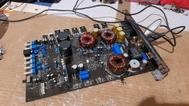
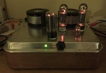
So after some time with my 3 deep BA-3 running, I am starting to get all the parts needed to rebuild it in pimp-my-amp fashion. It will be 3 deep too, using store standard IRFPs (not Harris). 6 deep with self-matched Harris’es saved for future possible not so likely project.

I have been contemplating starting a dedicated thread, and ZM encouraged me to, so here we are.

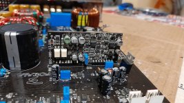
A bit of info on the first version, now being revisited. It was my first build, and I ended up having to troubleshoot some stuff and disassembling a few boards and so on. Result was a few pads gone bad, so for longevity they have to be replaced anyways.

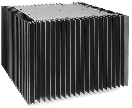
1: The case is a 5U 400 from a broken down F5T. It was mistreated, so a new back panel, bottom panel, UMS mounting plate and a new sink had to be ordered. This was good, since when replacing the sink I found that a crooked mounting hole had made one of the fets de facto break through the Kheraterm. A wonder I avoided a short...

Lesson: never buy a broken F5T! Build a new one, or something else.

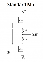
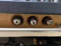
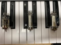
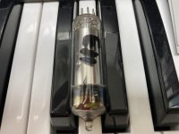
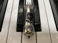
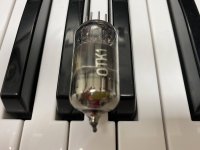
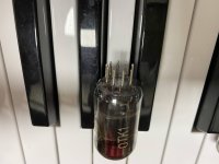
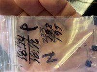
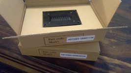
2: FE: I used Fairchild MOSFETs and LS JFETs. Never happy with what I have, I wanted to use Nelson’s specced parts. Toshiba FE MOSFETs have arrived from Japans underground through Prakit. Matched 10.14-16mA Toshiba JFETs arrived from Punkydawgs. But by some magic misfortune, there was only one pair in the bags. Punky does not know what happened, neither do I. And now he is out of 10mA’s... I got a full refund without discussion, so thank’s to Punky for that. But my goal was 10mA matched Toshibas, so it is still a real bummer. The LS’es bias too low, and I wanna avoid adjusting source resistors, something that in any case might not prove to bias them to spec.

So if anyone have a spare 10mA pair of J74/K170s just lying around gathering dust, you are welcome to chime in (hoping hoping).

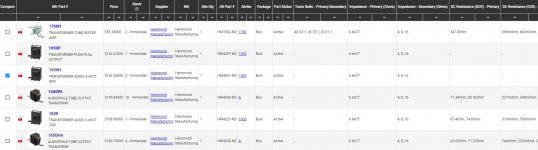
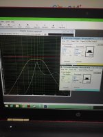
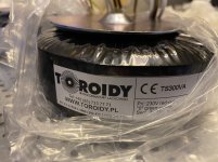
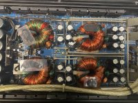
3: I use 32v rails at the moment. My transformer is a noisy Noratel 600va. I had some hum, but managed to almost completely remove it. But the rail voltage also limits my max bias. So I am going universal FW dual mono PSU inspired by ZM. 2x300va 18v secondaries Toroidy audio grades have arrived. Less power, but more versatile, and higher bias. Easy.

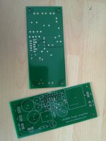
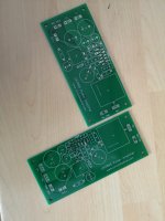
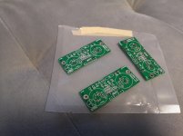
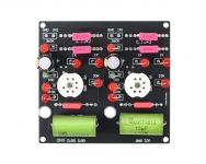
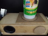
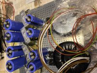
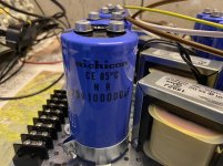
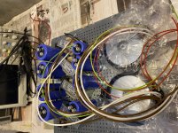
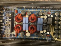
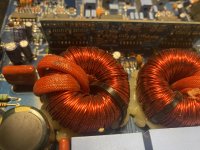
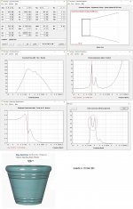
4: Attached is a pic of some of the PSU parts. I am going P2P. Absent from pics is snubber network and decouplers. It will be a tight fit, and this is with 4 caps not even included in the pic. Inductors are 10mH @ 5A Hammonds. I have some options here, building vertically, mounting trannies on the front plate, and so on. All insight and pointers are appreciated. Pic shows 94.000uf before inductors and 200.000uF after the inductors, per channel to run at approx 2A5 bias per channel. I have to scale up from approx 300kuF to 400kUf per channel, putting the extra capacitance after the inductors, provided enough space. Having more capacitance after the chokes is a deliberate choice, something about steep charging currents and all.

5: Layout-wise I think I need to put the bias boards on the back plate along with the FE. I also might mount the FE and bias boards horizontally, in PL fashion, but need a 3D printer or metal work expertise for that, we’ll see.

6: Soft start circuitry is not yet decided. I have 2x store soft starts, but might go thermistor. Insight appreciated, pushing the limits here both wrt the stores bords and CL-60s. Fuses will be on back plaate, one per channel. Disregard the terminal block for now. It is an alternative since I have long AC wires specced per tranny, but soldering would be nice and in both Papa’s and Choky’s spirit.

This will be done in slowish fashion, I do have a working amp.

Hope is to have a ripple free, close to Nelson-spec amp, with a hand built XL oversized PSU with full control over grounding scheme. We will see.

I hope this thread can be an arena for discussion, and learning, for me and perhaps also fellow builders.

I prolly forgot a bunch of things, but hence this thread.
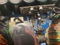
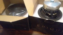
Attached is a most of the PSU section and my JFET pair absent it’s wife and husband.

Thanks to everyone who got me this far, looking forward to the continuation.

Regards,
Andy

Attachments

  • 4B478476-43D0-4559-B637-A47D97C01DE5.jpeg
    4B478476-43D0-4559-B637-A47D97C01DE5.jpeg
    450.8 KB · Views: 568
  • B5664901-CDED-4DC3-9504-21685F67AEF5.jpeg
    B5664901-CDED-4DC3-9504-21685F67AEF5.jpeg
    217.1 KB · Views: 589
  • 06F5473F-FD07-4AB7-8C78-605A26F61930.jpeg
    06F5473F-FD07-4AB7-8C78-605A26F61930.jpeg
    259.3 KB · Views: 557
  • 5AC68135-4E6B-4E61-88CF-41EE90DCB782.jpeg
    5AC68135-4E6B-4E61-88CF-41EE90DCB782.jpeg
    280.1 KB · Views: 556
  • 57FBFCDD-FA26-44CB-BB60-D832B0037F80.jpeg
    57FBFCDD-FA26-44CB-BB60-D832B0037F80.jpeg
    461.7 KB · Views: 556

Recommendations for ADC chips, and/or DSP chips?

I'm about to embark on a new project that is somewhat different from anything I've done before. I've designed and built plenty of DACs and preamps over the years, but I'm strongly considering purchasing a pair of studio monitors with built in DSP and built in DACs / Amps.

I'm looking at building a digital preamp. Turn the concept of taking a bunch of digital and analogue signals in and controlling the volume and spit out analogue completely on it's head.

In my mind I'm envisioning:

- Analogue input selectors.
- Phono stage preamp *without RIAA correction*
- All going into some ADC chips.
- DSP chip for applying the RIAA correction curve.
- Into a digital receiver chip which will also serve as digital input selector, SRC, and volume control.

So... I've never looked at ADCs before, does anyone have any recommendations on what chips to look at?

Likewise for DSPs.

New enclosure for 18LW2400, vented or horn

I own currently two 18 sound 18LW2400 drivers both in separate 120L sealed enclosures. Actually I am pretty satisfied with these but I would like to try someting totally different. I have played a little with hornresp but I'm not very familiar with it yet. I would like to have little help with horn options an some other opinions what should I try. Is it possible to put that driver in some kind of almost reasonable sized horn? With vented option I have been thinking 350 litre box tuned to 25hz. Here is datasheet for the drivers http://www.eighteensound.com/Portals/0/PDFs/18LW2400.PDF

A/B Listening Test - AK4499eq vs ESS9038pro

I wanted to share my entire post on soundnews.net - it provides useful context.

"Hi Sandu! Thanks for doing such a great job with your reviews! So NOT easy to use words to describe sound - you KNOW our language and are one of the few channels I view. I'm retired and somehow managed to end up with two DAC's in my system to replace my beloved ML 360S - with Spendor SP9/1, Pass Aleph 5 amp, C2850 clone preamp, ML No. 37 transport using the BEST AES/EBU cable Transparent ever made:

1) Gustard x26 Pro (dual ESS9038pro).
2) BRZHIFI DC500 (dual AK4499EQ).

I am finally ready to make the jump to online HI-Res Audio - QOBOZ for now.
But first, playing CD's on the ML 37 transport over AES/EBU, I wholeheartedly agree with your review of the Gustard x26 Pro; neutral, musical, palpable with great rhythm, pace and slam. However, not great using the USB interface from my MacBook Pro or my Windows 10 desktop.

Oddly, just the opposite is true with DC500. AES/EBU doesn't sound good at all. But, the Amanero USB interface sounds wonderful! I can directly compare CD source to QOBUZ for the same recordings (both16 bit, 44.1 kHz). Ultimately, I "feel" the DC500 (USB) edges out the Gustard x26 Pro (AES/EBU) but I don't think this an "apples to apples" comparison. Did you experience poorer results with Gustard x26 Pro USB source when compared to CD's? Is there a way to upgrade or improve Gustard x26 Pro's USB performance? I don't want to "keep" two DAC's in my system. I'm trying to figure out which one to sell. Streaming the DC500 sounds very good, timbre excellent; still a great pace & rhythm but not quite the slam as Gustard x26 Pro. What to do?!??

REVISION!!!
I need to update my comment on Gustard x26 Pro over USB connection. I moved the Gustard away from potential sources of noise - WIFI router, transport, preamp, turned off LED lighting and powered down the 65" flat screen. I had previously removed the wifi/bluetooth module from my Mid-2015 MacBook Pro which uses Core Audio (better than any Windows driver). Finally, things snapped into focus - I have palpable, musical experience. "Perhaps" the Gustard "is more sensitive to external noise? We are back to GREAT; comparable to CD's played over the AES/EBU from ML 37 transport. Equally, my problem playing CD's over AES/EBU on the BRZHIFI DC500 was solved!

I can now do a A/B comparison of both DAC's (ESS9038PRO vs AK4499eq) using the same USB QOBOS source or CD's. Of course, there are variables - equipment matching, impedance etc. I am using a very nice preamp and have a revealing system.

Initial impression - Playing acoustical music (classical & jazz), AK4499EQ seems more "musical". But one thing I've learned over the years - DON'T RUSH your listening experience. So, give me a couple weeks and I'll try to report back." -END of POST-

The ESS9038pro in the Gustard x26 Pro is VERY good, fluid, effortless, palpable, rhythmical & musical. So, I can only discuss subtle, nuanced differences. a) slightly too thick in the middle as though extra weight was given to the mid-range. b) less highs - what's there is sweet but less airy and detailed. I believe this is affecting the overall sound stage. c) slight mid-upper bass boom - not by much but I feel it's there. Again, a thoroughly enjoyable listening experience.

The AK4499EQ in the DC500. Simply the best digital listening experience I've had. Even more fluid, transparent & musical. Compared to the ESS9038pro, at first, it may seem less palpable; but it doesn't subtract or add anything to the music - it sounds natural. Beautiful highs - digital never sounded this good. I not only hear the instruments playing but the acoustics of the room in which they were recorded - more realistic sound stage. Like the ESS9038pro, there is a great pace & rhythm - if I'm not dancing, I'm at least tapping my foot. I think the AK4499EQ goes slightly deeper in bass, but in the Gustard x26 pro, the ESS9038pro has a little more slam and may be better suited to "rock n roll" - as an acoustical music listener, I'm simply not qualified to say.

Only balanced XLR outputs were used - no listening done prior to all equipment being thoroughly warmed up (> 1 hour).

What's it with Morel drivers?

Hello,

This thread isn't because I'm considering to buy and use Morel drivers but I was just wondering around on the internet looking at different drivers for fun looking at what makes them special and potentially good. Then I bumped on Morel.
I don't really understand their drivers. They have a very special way of putting them together. Their mid woofers have this very low profile design. I have seen it elsewhere with the Dayton Audio Esoteric series. There's probably a name for this kind of design, please tell me.
At first glance they seem insane(ly good). They have in some cases huge neodymium motors with voice coils in them as big as some entire drivers which can handle mind boggling amounts of power, some of their midranges have moving masses so low that it shouldn't be possible and most of their mid woofers seem to easily accomplish frequency response graphs any other manufacturer couldn't even dream.
But then you look at the exact numbers on the spec sheets and they are pretty weird in comparison with other drivers. Then you put them in box simulation software and optimize a little enclosure and then they don't really go that low, they are already at the edge of their Xmax at just a fraction of the kilowatts they're supposed to be able to handle and then when you expect that enormous voice coil to offer the best impuls response the world has ever seen but in fact it's one of the worst you've ever seen.
Morel isn't a huge name like Scan-Speak in the driver market but they are anything but small as well, their website is nice and up to date, Dynaudio has been successfully basing their drivers on Morel's for years and Morel won't be making all of their pretty expensive drivers by this principle because it's bad.
Is there something I'm missing? What's the secret to Morel drivers to using them correctly? Because they obviously SEEM like they have ou-of-this-world potentials but I don't understand how to unleash it. I'm just curious.

Sven

Focal Solid FP 1.800 class D issues - irs2184s

Hi guys

Amp is not in protect. Draws 1A at idle. No class D switching at all even with RCA signal and the output mosfets in.

New LM393, new IRS2184S, all new MMBTA92 + MMBTA42 transistors on the driver board, new gate drive diodes, D15,D18,D101 which are the small 3 diodes on the driver board - 1SS355TE - reads fine.

Exact driver board is also used in Orion HCCA-D2400.

IRS2184S pinout:

1 - square wave same freq as the injected signal thru the RCA
2 - 2.63v above neg rail
3 - neg rail
4 - neg rail
5 - neg rail
6 - 0v
7 - 0v
8 - 0v

I haven't changed the two optocouplers KPC117 as I can't find them in my country. Have not checked D102 - 1N5227.

I do have the schematics for the amp, but the driver board is missing there.
Can't figure out why the driver is not turning on.

Any ideas would help. Will provide the schematics if needed.

Attachments

  • 1.jpg
    1.jpg
    342.7 KB · Views: 430
  • 2.jpg
    2.jpg
    446 KB · Views: 494

RD Audio D9

Guy says the amp shuts off when playing doesn’t protect just shuts off .

I’ve had it on the bench playing for an hour and push on various parts of the board tapped the amp ect and it never shuts off like he described .

Any ideas ?

Attachments

  • 3F9108A2-E7C1-4D09-ACE3-97D88CE4BFC8.jpg
    3F9108A2-E7C1-4D09-ACE3-97D88CE4BFC8.jpg
    1.1 MB · Views: 126
  • 669B37BE-98DE-44DA-B09F-593F88B2A8FC.jpg
    669B37BE-98DE-44DA-B09F-593F88B2A8FC.jpg
    984.7 KB · Views: 129
  • 896932CE-8736-49FB-AF6A-6D15F40F96B3.jpg
    896932CE-8736-49FB-AF6A-6D15F40F96B3.jpg
    1 MB · Views: 100
  • 974D39FA-8BE0-45B4-841B-B177EDA4BF60.jpg
    974D39FA-8BE0-45B4-841B-B177EDA4BF60.jpg
    983.7 KB · Views: 98

The Best Books/Journal's to read for Loudspeaker design and Builds?

Hi guys,
I've just completed a 2 way passive, sealed enclosure loudspeaker build for a university project. Im currently looking for some more/best books and journal's I can use for a bit of further research and help on DIY loudspeaker builds and design's.
Can anyone help me out pointing me in the right direction?

p.s Ive read:

  • Designing, Building, and Testing Your Own Speaker System by David b. Weems

  • The Loudspeaker Design Cookbook by Vance Dickason


Thanks Very Much! 🙂

My Decware clone, Choke based PS

Hi Everyone

After building a couple of ZKIT2 from decware, and playing around with the power supply (essentially adding capacitance to PS to reduce hum), I decided to embark upon my own build based on the 84CS schematic. I changed up the power supply adding a choke and extra capacitance per my attached drawing. (CLC / RC / RC ) 10H choke and 800ohm resistor yielded correct B+.

I could not unhear 1.1mv hum near field on my 96db speakers with the ZKIT and RC filter, but LOVED the sound of the amp. Now ~200mv. I used PSU designer to simulate, but I am a hobbyist at best.

I built on 3mm stainless plate I had made at sendcutsend.com. THIS is a cool service and relatively inexpensive compared to a full chassis. They can laser cut many materials.

It sounds great. The rectifier seems happy.

This is my first scratch build (and 'design'). Now on to woodwork and awaiting transcendar output trannys.

I noted in the various schematics that the value of the grid resistor feeding power tube is either 300 (I built this way), 1K, or 2.7K (ZKIT2). Also the cathode bias resistor is either 100 (I built this way) or 150. I assume this has to do with different supply voltages. The voltages and bias values are all in line in my build so I am not stressing, but I have seen various iterations of the schematic and I am curious.

Also, any feedback on transcendar OPT?

Thanks for reading! 🙂

Attachments

  • IMG_2330.jpg
    IMG_2330.jpg
    49.2 KB · Views: 486
  • select_schematic.pdf
    select_schematic.pdf
    49.8 KB · Views: 300
  • IMG_2327.jpg
    IMG_2327.jpg
    476.9 KB · Views: 729

Proceed amp five

Hi, I’m currently reconditioning a Proceed amp five multi channel amplifier that initially had a hum in all channels with no source hooked up. I’ve located several out of tolerance/high ESR caps on all five boards. Also several defective trimmer pots. My question is does anyone have a schematic or service manual? I’ve worked around not having a service manual in the past but would rather have exact numbers for this amplifier.

Help w/ NAD 3020e

Hi all,

I'm going to preface my questions and potential stupidity by saying that I'm relatively new to Hi-Fi separates and therefore am fairly green in terms of technical issues. So apologies in advance and sincere thanks for any help.

I've recently picked up an NAD 3020e off eBay that's in lovely condition and was hoping to use it as a pre-amp for my Technics 1210 running into my Pioneer amp.

I'd (foolishly it seems) been under the impression that all 3020's had a separate pre-amp stage but it looks like I've got and bought the only one that removed that feature.

So my question is this: is there any way that I can use the 3020e as I intended without blowing the whole setup to hell?

It's been suggested that I could run the Tape Out from the NAD into the Line input of my Pioneer but I'm slightly concerned that the signal coming from the NAD won't have any of the warmth or tone that I bought it for. Would that be correct?

Any help would be greatly appreciated!!!

TKD 2CP-2511 measurements?

So I have a new TKD 50k 2CP-2511 and I'm seeing very strange measurements on the meter. Starting from the fully counterclockwise position, it measure 42k. As I slowly turn it clockwise, the resistance increases to 60k, then starts to gradually decrease. When it gets back to 42k, it's about about the 1/2 mark, and the last 1/8" or so drops rapidly from about 13k to almost 0.

This seems defective. I see no taper profile on the TKD datasheet that looks anything like this. Also, I just replaced the batteries in the DMM, and the measurements are repeatable.... so I don't think I'm out to lunch.

Is there anything to do other than return this?

For Sale: Aurum Cantus, Esoteric, Epique

All Sold:

Aurium Cantus AST2560 - Pair $225 - Sold
Aurum Cantus AST2560 Aero Striction Tweeter

Dayton Audio ES180TiA-8 - 4 total, 2 pairs - $200 Pair - Sold
Dayton Audio ES180TiA-8 7" Esoteric Series Woofer 8 Ohm

Epique E160CF-8 - Pair $300 - Sold
Epique E160CF-8 5-1/4" Damped Carbon Fiber Cone FEA Optimized Neodymium Speaker Driver 8 Ohm

Tested only and half have not even been opened. I spent the past year and a half building a three way speaker but life changes prevented me from finishing. Half of the speakers have been mounted and tested with very low wattage, the other half are new and unused.

Shipping is included from Kansas within CONSUS.

Please feel free to ask any questions and thanks for looking.

Attachments

  • IMAG1078.jpg
    IMAG1078.jpg
    346.1 KB · Views: 597
  • IMAG1079.jpg
    IMAG1079.jpg
    943.8 KB · Views: 592
  • IMAG1080.jpg
    IMAG1080.jpg
    883 KB · Views: 547
  • IMAG1081.jpg
    IMAG1081.jpg
    830.3 KB · Views: 533
  • IMAG1082.jpg
    IMAG1082.jpg
    831.4 KB · Views: 548

For Sale, Tubelab SSE build

SOLD

Selling my recently built Tubelab SSE, because I suddenly have too many amps.

Pictures are here.

Wired in basic triode configuration.

Output tubes are JJ EL34. Output transformers are Toroidy TTG-EL34, Made in Poland, enclosed in powder coated black metal bells. Power transformer is Hammond 274BX. Also contains a triad choke, Auri-Caps capacitors, Rean input connectors, and high quality components used throughout the build.

I custom designed and cut the enclosure from cherry veneered MDF. Very handsome look. All press-fit joinery, with "living" radii on the corners, which also provide some interior ventilation. Since it is not a metal enclosure, all components are individually wired to ground, per the advice of George at Tubelab.com.

Works beautifully. Sound is very warm and pleasant; the quintessential tube sound. More than sufficient power to drive my Bozak B-401 Rhapsodies.

Asking $700 obo, plus shipping.

SSE lacking brightness

I am in the final leg with my SSE build. It has moved from breadboard to an enclosure I built, and now I have been focusing on refining the sound so that I can down tools, and say that I have finished.

The top is some sort of heavy duty baking tray I rescued from recycling, and I like the rounded lines that are repeated with the base and toroids.

The bass is excellent, but it is lacking some elelement of brightness. I had been using a bluetooth source with Youtube, but I tested today with a CD player and good quality recording, and there is no doubt that there is something lacking in the upper ranges. For instance, Funeral for a Friend, after the initial synthesizer refrain, the band plays and there is a high hat, which is there, but sounding a bit muffled and not part of the sound stage.

It is a bit frustrating not having all the test tools, or a reference system to compare with. My SPP amp is not here, otherwise I could compare with that, but I remember that that had the 'wow' factor, which the SSE is currently lacking.

I am using UL with CFB. I have tried swapping tubes around. Currently have new JJ EL34s, but before had some old Telefunken EL34s liberated from a guitar amp. The driver is a Telefunken ECC81, but I have also tried a CV4024 (which does make the bass more dominant). While tube swapping, I managed to pick up an ECC83 without noticing (reduced gain and poorer sound), but it goes to show how you have to be careful and be organised when swapping tubes. Could have been something with a different pin out.

I have a DPDT switch for speaker impedance between the OPTs (where hopefully it will not get used during running), and I am pleased with that solution. I will be adding a 300ohm 5W resistor from the line to ground for each speaker connection to protect against no speakers. I am thinking this should be as standard as adding a fuse to the power supply - are there any nay-sayers?

I am pleased with the layout. The signal wiring is short and down one side, the power down the other, and the outputs at the back. Only downside is the proximity of the tubes to one of the OPTs, but I may well mount them vertically to get round that. (There is a perforated base to be fitted).

As I am sure most hobbyists will agree, the hard part is keeping the momentum going after the breadboard is delivering the goods, so that there is something that is safe and presentable. I am hoping that I will be able to sell it eventually for the cost of the materials, since it is hard to counter the 'what do you need another one for?' questioning of my better half. At least I am fortunate that she is appreciative of the detailed sound, and she is a music fan.

Attachments

  • amp4.jpg
    amp4.jpg
    353.2 KB · Views: 449
  • amp1.jpg
    amp1.jpg
    659 KB · Views: 465

Rephase Room Correction

So I've been playing with rephase and room correction with my DEQX for a long time and I wanted to share some of my recent results in the hopes it helps someone else. I have had mixed results in the past using room correction

attempting to take measurements from a single listening position or even from 3 ft from the speaker and then trying to EQ the room.


I've always felt like the results were marginal or even made the sound worse. Well what Ive learned is there can be a huge learning curve (Im still learning) after years of playing with this stuff. SO dont give up on it ! Anyhow the best rephase tutuorial Ive found was by someone who goes by 'bear' (ive attached the tutorial).


Anyways, I added something of my own that I just thought of that made a HUGE difference to the results.


Previously Ive always just taken a measurement from a single point for each speaker and then tried correcting the phase and FR from that point. But I think the flaw is of course when you move your head 1 inch or more from that spot the FR changes and you're back at square one.

So I finally tried taking measurements from 48" and 78" at 9 degree increments (0 to 45 degrees) for each speaker and then vector averaging the measurements in REW and then correcting the resulting phase using THAT measurement. Also I started the sweeps at the lowest frequency wavelength from the distance measured. ie the 48" measurement is 285hz, the 78" measurement was 175hz. What a difference. I highly suggest trying this and creating fir filters this way if you havent already.


I think it does a way better job of averaging out the FR and phase in the room and the reflection come back more in phase which opens up the sound stage. Being that every room is different I dont think it would be possible for speakers to be perfect for your room out of the factory and Im not aware of any ARC that corrects using this method automatically.


I had almost given up on room correction until I tried this and its made enough of an improvement that Im going to continue attempting to fine tune it. Let me know if you have any questions and Ill try and answer.

Want to build a 3 way with at least 8” for the Bass Driver

Hello all

I am almost finished a build of Microtower Castles using FR Alpair 7as (they sat for a couple of years on the shelf!) and am already looking to commence my next project.

Looking for a 3 way this time, with a bass driver of between 8-10”

I am familiar with the website from Troels, are there any other options available?

Note, I am looking to build not design, at least not yet!

Tks

TDA2050 better than LM3875 and transformer VA rating

Hi All,

I seem to recall reading somewhere that TDA2050 gave a more refined sound than LM3875 in gainclone implementations. Any views on this?

Also, I have 2x300 VA transforners (20V secondary) which I intend using for my LM3875 implementation. Is it corect to say that teh higher the VA rating of the transformer the better? I have seen that others are typically using only 120-225 VA transformers.

Ryan

FS JVC/Victor TT-81 direct drive turntable motor

Up for sale direct drive Victor TT-81 turntable motor deck.
Excellent working condition. Asking $400US .This is Japanese version with 100V power voltage. 120V step up transformer will be included.
VICTOR TT-81‚ÌŽd—l ƒrƒNƒ^[

Attachments

  • DSCN0282.JPG
    DSCN0282.JPG
    844.4 KB · Views: 372
  • DSCN0283.JPG
    DSCN0283.JPG
    675.7 KB · Views: 355
  • DSCN0281.jpg
    DSCN0281.jpg
    771.2 KB · Views: 435

Overview from world's best historical and currently available electr/audio Magazines

Overview from world's best historical and currently available electr./audio Magazines

This could be an interresting collection of all magazines, not only english, French, German and Japan editions - we have more than 200 countries:
http://thumbs.dreamstime.com/thumb_367/1235114020ss78pr.jpg

I will start with a very small amount of editions and hope of much more, especially from the east European countries, but also far east countries, Brazil and the spain language countries (in the meantime relativ small losses by translate about "Fine-Reader/Google"):

Please note: no clean comparable test magazine for HiFi/audio like stereophile or the new "l' audiophile" here included - about this magazine listings go to
Audio Magazines


1) Electronics World
Electronics World - Electronics World
File:Electronics World Sep 1959.jpg - Wikipedia, the free encyclopedia
http://www.marklev.com/JC3/JC3-from-Electronics-World.jpg
Amplifier Articles in Electronics World & Elektor

2) Ремонт электронной техники (Repair of electronic components, Russian language - in this country all devices will be repair, even cheapest stuff like cell phones, dish receivers, cheap MP3 players and all the other electronic stuff)
http://www.radio-portal.ru/book/%C6...%ED%EE%E9%20%F2%E5%F5%ED%E8%EA%E8/2000_06.pdf
Æóðíàëû "Ðåìîíò ýëåêòðîííîé òåõíèêè"
http://www.shema.ru/0_s/mwo/SANYO/EMG_430.pdf
http://www.all-library.ru/zhurnaly/texnicheskie/1753-remont-i-servis-11-2009.html

3) 'l Audiophile (French)
http://6bm8.lab.free.fr/Documentations/Revues/Audiophile/index-1977-1988.html (index-1977-1988)
https://web.archive.org/web/20090218161354/http://www.audiophile.lu/index_fr.php
currently other magazine than from old days. Old magazines available on CD:
https://web.archive.org/web/20100518094713/http://nicolas.davidenko.perso.sfr.fr/revue/revues2.htm
https://web.archive.org/web/20100130100553/http://nicolas.davidenko.perso.sfr.fr/index.html
https://web.archive.org/web/2023120...LY/pXnJajbGgI4/s400/audiophile-couv-light.jpg
https://web.archive.org/web/20090205150033/http://www.audiotechno.fr/html/realisations.htm

4) "無線と実験" (MJ magazine, Japan)
all informations there:
http://www.diyaudio.com/forums/soli...sen-jikken-yearly-index-1924-2009-wanted.html

5) Elektor/Elektuur (German, Englisch, Dutch)
ELEKTOR.nl | Elektronica: Embedded Microcontrollers Audio Digitaal Analoog Testen Meten
http://miketimmer.nl/wp-content/uploads/Elektuur.jpg
Elektor Artikelsuche
paX: Audioverstärker mit Fehlerkorrektur - ELEKTOR.de | Elektronik: Analog Digital Embedded Mikrocontroller Audio Messtechnik
paX power amplifier
http://www.diyaudio.com/forums/solid-state/165165-edwin-20-watt-elektor-1970-may.html

6) ELRAD (German, no longer available, no successor magazine)
http://shackman-electrostatic-loudspeakers.reromanus.net/elrad-titel.JPG
Elrad (magazine) - Wikipedia, the free encyclopedia
HMG - Presse-Informationen - Heise Zeitschriften Verlag - 20.12.2005
heise online - ELRAD auf DVD
Shackman DIY Electrostatic ESL/ELS Loudspeakers and tweeters. Tube/valve amplifiers Röhrenverstärker. Elektrostatische Lautsprecher Elektrostaten-Selbstbau Audio engineering Literature

7) "Chip" and "populäre Elektronik" (German, no longer available, no successor magazine)
http://www.gw-home.de/images/elektronik.jpg
http://resources.emartin.net/blog/pic/Populaere-Elektronik-1982-10-sm.jpg
Populäre Elektronik ? Wikipedia
1978-1983 Vogel-Verlag (emartinnet)

8) TAA ("The Audio Amateur") and "Speaker Builder"
http://www.arcdb.ws/ST70C3/AudioAmateur_4_1977.jpg
http://www.carveraudio.com/sb[1].jpg
http://www.alkeng.com/bruce2.jpg
AUDIO AMATEUR BACK ISSUES
http://www.passdiy.com/pdf/citation.pdf
A75 Part 1
https://www.wilmslow-audio.co.uk/catalog/index.php?cPath=39
Ribbon Tech
The Maverick 2's

9) Funkschau (German, in the early days similar to Japan's MJ magazine)
http://www.guenthoer.de/doku/funkschau-2284titel.jpg
http://www.suertenich.com/html/radios/Concert_Boy_Funkschau.jpg
http://www.suertenich.com/html/radios/grundig_58.html
http://www.addx.de/textarchiv/archiv-funkschau.php
http://de.wikipedia.org/wiki/Funkschau
http://www.radiomuseum.org/forum/funkschau_1944_jahresuebersicht.html
http://www.jogis-roehrenbude.de/Russian/Funkschau-Ru-Roe.pdf
http://www.earlytelevision.org/images/FunkschauNov1936_1.jpg
http://www.earlytelevision.org/images/
Projects by fanatics, for fanatics
Get answers and advice for everyone wanting to learn the art of audio.
Join the Community
507,648
Members
7,882,654
Messages

Filter

Forum Statistics

Threads
405,961
Messages
7,882,654
Members
507,648
Latest member
nguyenbatrinh