New Cherry NDFL amp

Hi Folks, first post from a relative newbie and former lurker, so here goes...hope you can read the circuit....its long, bear with me.

I am actually a switch mode PSU designer who moved into analogue and mixed signal semiconductor sales... it pays more!My background is Linear Tech, Burr Brown, Unitrode, TI but I have always had a hobby of audio dating back to when I was 11 years old...a long time ago now. Now I am selling motors..more on that another day.

I first experimented with nested feedback by putting a 400W MOSFET amp inside the feedback loop of a OPA627. Fixes the DC drift just great...and actually works quite well. Why...the sales director wanted 'more bass'. I reckon he just needed to clean out his ears...

But it got me interested in nested feedback, and I read the Cherry papers. And wished I could remember more of the stuff I learned at college.....that's what sales does to you.

The original objective was, using the Cherry paper (with his permission for hobbist use incidentally), duplicate his results and make a judgement as to the subjective audio quality.
As time went on the project slowly mutated into a 'make it as best you can' then apply NDFL feedback.

The input stage was elaborated to a CFP type in an attempt to achieve best linearity with the minimum additional complication.

The Rush stage was retained but with the inclusion of R21 to limit the maximum stage gain to something sensible...I am a pom after all so good to have a UK circuit in a Monash Univ. paper!

The VAS transistor was chosen as a BF469, to preserve as much HF performance as possible, rather than use a MJE. I appreciate other much better (and easier to obtain) transistors exist now.

Likewise the current source for the VAS stage was elaborated to a cascode. Later this was found very handy as it was modified to dethump the amp at turn on and diodes were added to the supply rails to prevent positive feedback thumping the amp at turn off.

The output stage was eleaborated into a CFP driver with common emitter output. The object here was to present minimal loading to the VAS, maxmimised voltage swing and allow multiple pairs of output devices to be driven, if a high power version was required.

The prototype used Rod Elliots P03A as the driver...thanks Rod!

The output and driver transistors are the newish On Semi MJE15035 and 36 with MJL4XXX outputs.

The thermal tracking is split into two, one Vbe multiplier tracking the driver drift, the other tracking only the output temperature mounted smack on the face of the output transistor. This appears to work very well.

In the Cherry paper he suggests that including the output stage withn the CDOM loop is acceptable, it is certainly not using this more elaborate and possibly slower output stage, hence the position of C9 is conventional except that it is now part of a nested system.

The choice of transistors is not totally trivial in this design BTW, quite a lot of work was undertaken to prove the CFP stages were stable.

What does it sound like...well I think pretty good, no transistor 'edge' and very good resolution. It has powerful
but uncoloured bass too.

BTW some years ago I built the Self amps and verified his results..yes he's right THD+N circa <0.0005 in a 80KHz BW (APS1 noise floor stuff) but the amps sound diabolical on music, still have the pcbs if anyone interested. For anyone trying this, wiring up the amps and the test equipment is more critical than the choice of transistors...back to the Cherry amp..

Spice analysis (thanks LTC, great free tool!) shows the overall loop gain to be very similar to an amplifier with 2 pole CDOM feedback, very high gain at low frequency, followed by a 2 pole roll off reducing to a single pole at unity. But this is achieved in a more controlled fashion, so I suspect, but cannot prove, lower overall distortion.

What do you guys out there in DIY land think? 😀 or :bawling:

And thanks to Hugh Dean for tea and sympathy...sympathy for trying to build this thing in the first place!

Attachments

  • cherry_1_1.jpg
    cherry_1_1.jpg
    98.8 KB · Views: 3,588

Measurements of Turntables/Record Players - in which Test Magazines to find

There are probably a wide range of audio/hifi magazines around the world (in many languages).

here some examples:
StereoNET Expands into NZ with Purchase of AudioEnz | StereoNET Australia - Hi Fi & Home Cinema News
SoundStage! Hi-Fi | SoundStageHiFi.com - SoundStageHiFi.com Equipment Reviews
MJ Magazine (formerly Musen to Jikken) - Yearly Index from 1924 - 2009 wanted
Stereo Sound ONLINE
Home Page | Hi-Fi Choice
https://www.whathifi.com
https://www.theabsolutesound.com
also there are online magazines, e. g.
https://www.audiophil-online.com
https://www.lowbeats.de

Which of these magazines also carry out measurements with regard to speed accuracy, SNR etc. ?

Obviously there aren't many of them. Even stereophile - go to
https://www.stereophile.com/content/lack-phono-measurements-stereophile
perform this only in individual cases like this very rare examples:
https://www.stereophile.com/content/linn-sondek-lp12-turntable-lingo-power-supply-measurements
https://www.stereophile.com/content/linn-lp-playing-system-measurements

It seems to be, that such measurements are usual at the u.s. magazine AUDIO - go to
https://static1.squarespace.com/sta...41acad/1489563683682/Plattenspieler+Audio.pdf

Any few measurements are to find the web:
https://www.audioasylum.com/message...ents-of-harmonic-distortion-from-my-turntable
https://www.woodsongaudio.com/service/thorens-td124-main-spindle-bearing-rebuild
https://stereo-magazine.com/review/sme-model-12-review

In old magazines like those in post #38-41 under
Overview from world's best historical and currently available electr/audio Magazines
so as in the magazine "l Audiophile" - go to
http://6bm8.lab.free.fr/Documentations/Revues/Audiophile/1977-1988/01/PHONO/PHONO.html
and
http://6bm8.lab.free.fr/Documentations/Revues/Audiophile/1977-1988/42/VERDIER/VERDIER.html
there are more measurement results to find.
Last both links are to find under
http://6bm8.lab.free.fr/Documentations/Revues/Audiophile/index-1977-1988.html

Thanks for advices to magazines with measurement results in their test reviews.

Studio Projects C1 Condenser Mic fading on and off at random

Hi Everybody,

I have been asked to take a look at a Studio Projects C1 condenser microphone which is basically not working correctly. After plugging it in, there is no life. Then it starts to hum and come to life where if you tap the mic it is working. When I speak into it, it gives good quality vocal then it cuts out and dies again. It will remain of for a while and then come back on itself.
I have checked the components on the pcb. All seem good. I’ve went over all the solder joints. All are good.
Has anyone here come across the likes of this before? Could it be the capsule?
I attach a few pics.
I am going to replace the J305 Incase it is not working correctly. I have removed it from the pcb to test it. It seems ok but I might replace it anyway. Other than that I’m in need of a little help.

Kind Regards,
Paul

Attachments

  • E9A7A7A4-9937-448C-B382-AD720A672005.jpg
    E9A7A7A4-9937-448C-B382-AD720A672005.jpg
    1,007.4 KB · Views: 221
  • 1F2989D9-5842-49CC-B191-FAC055C8C1A7.jpg
    1F2989D9-5842-49CC-B191-FAC055C8C1A7.jpg
    669.7 KB · Views: 185
  • FC841C6A-EFF7-4C2A-BAE7-125CCD1D3B2C.jpg
    FC841C6A-EFF7-4C2A-BAE7-125CCD1D3B2C.jpg
    783.3 KB · Views: 188

Need To Choose Hashimoto Choke

I'll be building a Sunvalley 300B amp (their SV-S1616-D with Hashimoto output transformers). This is a new amp that will be released early September of 2021.

I'm going to build my own chassis and can make the width larger so I can then mount a choke on the exterior of the top plate along with the other transformers. The kit has a small choke mounted inside the amp. I'll be using a Hashimoto choke instead of the small choke that comes with the kit and now need to choose which Hashimoto choke. I found a schematic that shows this amp's circuit (attached in link below) and the only info for the choke value used is 4H.

I also own a Triode Labs EVO21 300B amp and found that they use the Hashimoto C-10-200W. That choke has an inductance value of 10H/2.5H.

The choke that I'm also considering for replacement of the kit's choke is the C-16-150W. That has an inductance of 16H/4H. The DC resistance is lower for the Triode choke and I'm trying to pick the best one for this Sunvalley circuit. I don't have the amp yet so can't measure the choke in their kit. However, the Hashimoto choke will probably be a better choice.

Would you choose the Hashimoto C-10-200W the same as Triode uses or the C-16-150W?

Here are the specs:

C-10-200W
Inductance: 10H / 2.5H
Rated DC Current: 200mA / 400mA
Max. DC Current: 250mA / 500mA
DC Resistance 140 / 35 Ohms

C-16-150W
Inductance: 16H / 4H
Rated DC Current: 150mA / 300mA
Max. DC Current: 180mA / 360mA
DC Resistance 200 / 50 Ohms

Which one would you pick?

Thanks for any help,
Richard

Here's the link to the schematic of this amp:

Sunvalley SV-S1616-D 300B Schematic

Input Capacitance of a Triode-Connected D3A

I have the Telefunken data sheet for the D3A.

It does define the input capacitance for triode-connection.

However, being the data sheet is largely written in German, and I can only read English, I am having difficulty in obtaining the following information from the data sheet for the D3A:

Cathode to Grid Capacitance, Triode-Connection

Grid to Plate/Anode Capacitance, Triode-Connection


I need this information so I can calculate the Miller capacitance for a triode-connected D3A.

Can anyone help?

Thanks in advance!

Hello from VT

My name is Lawrence and I live the village of Williston VT. I've recently taken on a diy project where I'm going to try to restore an old GE solid state stereo console (a533g) from around 1969. I thought I knew a lot about stereo equipment, but I've been humbled by this ordeal and have come to know I don't know jack.

I will be leaning on you all heavily over the next several months and hopefully be able to share with you my experiences.

Hope you're all staying safe and well.

Regards,
Lawrence of Vermont

Please help. Bassbreaker 18/30 - NO SOUND!

Hi everyone, complete noob to message boards, so I hope this is okay. I have a Fender Bassbreaker 18/30 combo amp that recently stopped working. I played it for a gig one night and the next day, no sound. I get a little bit of noise when I plug a cord in and touch the end, but nothing with an instrument plugged in. I checked the inline fuse with a multimeter and it seems fine, I inspected the tubes visually and nothing pops out at me. All of the tubes glow orange when powered up, the preamp tubes only a little. I'm hoping someone can give me some idea as to what my issue could be. Thanks

SRC4392 + ESP32

Hi All,

I am working on a DSP based on ADAU1466 + SRC4392, controlled by an ESP32 through SPI interface.

My programming skills are not so great, so i where wondering if anyone have a sketch they would be willing to share with me?

Currently i have tried this code which does not seem to do the trick;
Code:
#include <Arduino.h>
#include "PCF8575.h"
#include "SPI.h"

unsigned char audioSRCCom(unsigned char address, unsigned char data, bool read = false);
void audioSRCWrite(unsigned char address, unsigned char data);

unsigned char errorCode;

#define SPI_SRC   4
#define SPI_ADAU  5

#define AUDIO_SRC_R14_INTMASK	0xF4	// CRC, parity, validity, bip encoding, and dir unlock unmasked
#define AUDIO_SRC_R18_INTMODE	0xAA	// interrupt mode to level change
#define AUDIO_SRC_R19_INTMODE	0xAA

PCF8575 exp1(0x21);
PCF8575 rexp(0x22);

const SPISettings settingsA(1000000, MSBFIRST, SPI_MODE3); // Store SPI transaction information to settingsA

uint8_t audioSRCCom(unsigned char address, unsigned char data, bool read) {
  uint8_t Response = 0x00; // Set response to 0
	digitalWrite(SPI_SRC, LOW);
  SPI.beginTransaction(settingsA);
  SPI.transfer(address);
  SPI.transfer(0);
  SPI.transfer(data);
  SPI.endTransaction(); 
  digitalWrite(SPI_SRC, HIGH);
  if (!read) return Response; // End if only write session
  delay(1);
  digitalWrite(SPI_SRC, LOW);
  SPI.beginTransaction(settingsA);
  Response = SPI.transfer(0xFF);
  SPI.endTransaction(); 
  digitalWrite(SPI_SRC, HIGH);
  return Response;
}

void src_statuses () {
  Serial.print("SRC Interupt Status: ");
  Serial.println(audioSRCCom(0x02, 0x01, true));
  Serial.print("SRC Ready Status: ");
  Serial.println(audioSRCCom(0x0A, 0x10, true));
  Serial.print("SRC Ratio Status: ");
  Serial.println(audioSRCCom(0x0A, 0x20, true));
}

void initiate_src4392 () {
  src_statuses();
  audioSRCCom(0x7f, 0x00); // Initial write to page register, selecting page 0
  audioSRCCom(0x01, 0x80); // Software reset
  audioSRCCom(0x03, 0x31); // Port A format I2S, slave mode, src->porta
  audioSRCCom(0x04, 0x01); // Port A clock to MCLK/256 (48k)
  audioSRCCom(0x05, 0x41); // Port B format I2S, slave mode, mute output (port is not used)
  audioSRCCom(0x06, 0x01); // Port B clock to MCLK/256 (48k)
  audioSRCCom(0x08, 0x31); // Bypass Mux RX1, AESMUX BYMUX, LDMUX BPMUX, Enable AES and TX
  audioSRCCom(0x0D, 0x08); // DIR reference clock = MCLK
  audioSRCCom(0x0E, 0x08); // Automatic DIR-mute for loss of lock
  audioSRCCom(0x0F, 0x12); // Registers 0F, 10 and 11; PLL1 configuration. Values from datasheet: P=1, J=8, D=0
  audioSRCCom(0x10, 0); // Registers 0F, 10 and 11; PLL1 configuration. Values from datasheet: P=1, J=8, D=0
  audioSRCCom(0x11, 0); // Registers 0F, 10 and 11; PLL1 configuration. Values from datasheet: P=1, J=8, D=0
  audioSRCCom(0x16, 0xF4); // CRC, parity, validity, bip encoding, and dir unlock unmasked
  audioSRCCom(0x18, 0xAA);	// interrupt mode to level change
  audioSRCCom(0x19, 0xAA);	// interrupt mode to level change
  audioSRCCom(0x2d, 0x42); // Port B as input, MCLK as Ref, Mute Disabled, Volume tracking leftch.
  audioSRCCom(0x30, 0x07); // Set left channel volume -3.5dB
  audioSRCCom(0x31, 0x07); // Set right channel volume -3.5dB
  audioSRCCom(0x01, 0x3f); // Activates the chip, remove soft RST, Enable all.
  delay(10);
  src_statuses();
}

void setup() {
  delay(1000);              // 1 second startup delay
  Serial.begin(9600);    // Initialize the USB serial port for debug
  pinMode(SPI_SRC, OUTPUT); // src4392 CS pin
  pinMode(SPI_ADAU, OUTPUT); // adau1466 CS pin
  digitalWrite(SPI_SRC, HIGH); // Pull SRC4392 CS pin HIGH
  digitalWrite(SPI_ADAU, HIGH); // Pull ADAU1466 CS pin HIGH
  exp1.pinMode(P5, OUTPUT); // ADAU1466 Reset pin
  exp1.pinMode(P6, OUTPUT); // SRC4392 Reset pin - H/W Linked to ADAU1466 Reset, if ADAU1466 RST is low, SRC4392 will be low for atleast 300ms after ADAU1466 turns high
  exp1.begin();
  exp1.digitalWrite(P5, HIGH);
  exp1.digitalWrite(P6, HIGH);
  delay(10);
  SPI.begin();
}

void loop() {
  initiate_src4392();
  delay(5000);
}

Serial response from the sketch is:
SRC Interupt Status: 0
SRC Ready Status: 0
SRC Ratio Status: 0
SRC Interupt Status: 0
SRC Ready Status: 0
SRC Ratio Status: 0

Physically checked that hardware rst pin is 3.3v, and i am can program ADAU1466 through same spi interface

Schematic for the SRC chip:
Screenshot by Lightshot

Onkyo NR609 amp board

Hi all.

This is the board from a Onkyo NR609 AV receiver, complete with what IO assume is the preamp board, and I also have the original power transformer, as well as the small AC in board.

I was wondering, is there a way to switch on this unit and use it as a test amplifier or 7 channel power amp? I know it does not have the best sound quality, just thought it a waste to chuck it.


IMG-20200419-163129-resized-20200419-043153726.jpg


IMG-20200419-162644-resized-20200419-043004873.jpg


IMG-20200419-162626-resized-20200419-043004602.jpg


IMG-20200419-162835-resized-20200419-043005162.jpg


All else fails, I will be using the transformer for my APEX build, can always strip the main board and use the heatsinks and other bits.


I would however, appreciate some help in trying to get this to work, if its possible.

Regards
Cedric

ADP7118

Very simple question.

On page 16 of the datasheet it is explained how to keep the noise of externally configured regulators low.

The theory makes sense. Reduce the gain of the circuit down to unity at high frequencies so as to not amplify the broadband noise by the DC circuit gain.

What I am not understanding is how AD arrive at a DC gain of 10, for the configuration shown, using the 5V, fixed, regulator.

The datasheet explains that all the fixed voltage devices work at a gain of unity. So to get the 5V to output 10V it needs to be configured for a gain of 2. Which is what you'd expect given the feedback resistor values with both being 100k.

What am I missing?

How much polyfill to get rid of internal standing waves in a 2.16lt sealed box?

Can some please calculate the weight of polyfill required to get rid of internal standing waves of a 2.16lt sealed enclosure. Or is there a chart recommending the amount of polyfill in weight for enclosures of different sizes.

Box internal dimensions
Height:214mm Width:82mm Depth:132mm

1st mode standing wave wavelengths
Height Width Depth
801 Hz 2.09 KHz 1.30 KHz

PS: Since the box has been downsized from 11.5lt to 2.16lt, not sweating of the effect on Qtc.

HP 6263A

I picked this HP PS up at a hamfest awhile back for 10USD. It has no output. The raw DC is there. I can't find the manual for it. Electrotanya has the "B" model manual. Can anyone direct me to the "A" manual? Or do you know it they're close enough to use the "B" manual I have. A recap, new cord and cleaning of the controls are mandatory I know. Someone has also added an extra rheostat to the front panel. I'd like to attempt to get it working before I scrap it it. Thanks!

Attachments

  • thumbnail_image_50417665.jpg
    thumbnail_image_50417665.jpg
    311.6 KB · Views: 82

Testing / Verification of Gedlee Abbey Kit?

I'm currently building a pair of Gedlee Abbeys from a kit which was purchased by someone else some time ago. I've assembled the cabinets and I'm about to do the crossovers and final assembly.

I was wondering if anyone had any recommendations for measuring these speakers after completion, just to make sure I haven't done anything egregiously wrong. I have arta and a measurement mic, but it would be helpful if someone could recommend the axis, measurement distance and expected response.

Alternately, I could do an impedance sweep of the final system, but I can't seem to find an impedance graph of this speaker.

I understand Dr. Geddes is retired so I'd like to avoid bothering him directly; curious if any other Abbey builders have done any measurements.

Very much looking forward to hearing these speakers!

Electrically quiet isolated DC-DC convertor

I have a portable boombox built with a Raspberry Pi and IQaudio DAC . This runs from a 12V SLA with the Rpi powered via a Murata NDY1205C isolated DC-DC convertor . I am experiencing issues with 5V noise , which manifests at random as quiet whistling and crackles . No issues running from a separate 5V power bar or external PSU . The NDY device is connected as per the datasheet with low-Z 100uF bypass capacitors on input and output and cables are as short as possible . Minimum current for the device is 150mA , I measure 165mA drawn by the Rpi/DAC combination . Maybe I'm expecting too much from the NDY in terms of noise , but has anyone else used this device or similar DC-DC convertors and obtained decent noise performance without adding additional LC filters ?

Most frustrating , my scope is on the blink . First time in years I've needed to poke around in equipment 🙁

cheers

316a

TU-8600s Another Successful Build

Just finished the build. Was able to source all resister values in .5w Takman units. Except the 2w and 3w resistors. It was not easy. I heard Takman will no longer be producing them? Used a quad, matched within 1%, Vcap set. Of course, silver solder everywhere. Also, did the headphone output resister mod posted by bhk1004. Thanks for that.

First power on with no issues. All test points tested good for expected values. Except one, TP9. Should be 175v as TP10 was, but was 167.7. Could see one of the 12ua7 tubes was glowing a lot more on the bottom than the other. I know tube brightness is not a way to judge, but to me, it looks pretty obvious this one is pulling more current than the right one, causing the voltage drop. The voltage drop followed the tube when I swapped them with each other. This was supposed to be a matched pair, which usually means also balanced. Working to get another set from the ebay seller.

WD 300B's are the new reissue units they are making now.

So, far very pleased with what I am hearing. Speakers are 90dB 8Ω so no problems running them at my usual listening levels. 50 hours of burn in so far. We will see if anything changes when I hit 100 and 200.

The WD 300B's have a very pleasing glow to them once the lights go down.

Looking hard at the upcoming Sunvalley P1616D for next build project.

Attachments

  • Main Board finished 1.jpg
    Main Board finished 1.jpg
    264.1 KB · Views: 381
  • Testing Board 1.jpg
    Testing Board 1.jpg
    319.8 KB · Views: 372
  • 12ua7 current draw 1.jpg
    12ua7 current draw 1.jpg
    958.5 KB · Views: 375
  • Night light 1.jpg
    Night light 1.jpg
    671.2 KB · Views: 378

Trimming Veneer around Tweeter

Hello,

New member, and in the process of my first speaker kit build (building my own enclosures). My question is around veneering, specifically around the tweeter recess. Experimenting on a test board, I cut the outer recess circle and the inner through-hole for the tweeter and woofer, then veneered the board. Routing out the through-hole is no problem for either. But for the tweeter, the depth of the recess (3 mm) is less than the height of the bearing on my flush trim router bit, so I can't use that to trim the veneer.

Should I route the smaller hole after I veneer (I prefer routing the hole early when there is less at stake build-wise), or is there some tool/trick to trimming the veneer around a shallow recess?

Thanks

Trying to mellow out Klipsch KG 4.5 tractrix horn

I bought a pair of Klipsch KG4.5 speakers in good shape. I kind of like them (my first horn speakers), but they have a harshness in the treble that I'm trying to tame.

So far I've applied a layer of duct seal (a la Planet10) to both the tweeter horn and the woofer frame, which has helped gain clarity and smoothness. But the tweeter still has a little sizzle to the top end that bothers me.

A lot of people have said to replace the crossover capacitors, but they look like reasonable quality metallized Mylar film. How bad can those possibly be?

Here's the crossover schematic:

Kilpsch_kg-45_crossover.jpg


I was experimenting with putting a resistor across the + and - terminals of the tweeter. When I put a 50 ohm 10W wirewound there, the highs definitely get smoother and less brash, but maybe too 'dead.' When I put 100 ohm 10W it smooths the highs just a little tiny bit.

Here's what I've done to it:

Kilpsch_kg-45_crossover_MODIFIED_HF.png


Right now I'm listening with the 100 ohm there, and I think I want to try something like 82 ohms (split the difference between 50 and 100 ohms).

My question is -- Am I doing something incredibly stupid and wrong? I mean in general terms. I don't have the actual driver specs, so I understand that the crossover can't be properly analyzed from just the schematic. But in general terms, is putting a resistor across the tweeter likely to cause a problem?

Am I just attenuating the tweeter output by setting up a simple voltage divider between the series resettable fuse (that "polyswitch" thingie, which has 0.5 ohm internal resistance) and the parallel resistor?

Thanks...

The best 8" mid bass

Working on a new project of 3way speaker with follow configuration high sensitive Twitter SB Satori TW29BNWG-4 and 8" Mid-bass (over 92- 93 dB) to driven by tube amp,.. and 2 x 8" Subs VISATON GF200 driven by extra active D Class amp.

I cannot make a decision for mid-bass. In narrow selection are now:
- VISATON 200B
- Acoustic Elegance TD8M
- Beyma GH40 8 OH

Any suggestions or your experience are very welcome.

Pro-ject Pre Box Digital S2

Lightly used, everything works, comes with the remote. Condition, "as new"

Perfect mate with Tidal MQA.

Price 240€

Shipping possible to anywhere, ask for shipping quote

Attachments

  • IMG_20210813_194240.jpg
    IMG_20210813_194240.jpg
    472.3 KB · Views: 111
  • IMG_20210813_194748.jpg
    IMG_20210813_194748.jpg
    646.4 KB · Views: 113
  • IMG_20210813_194805.jpg
    IMG_20210813_194805.jpg
    656.3 KB · Views: 106
  • IMG_20210813_195123.jpg
    IMG_20210813_195123.jpg
    397.8 KB · Views: 109

LuDEF kit packages

Presenting thread here: LuDEF


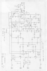
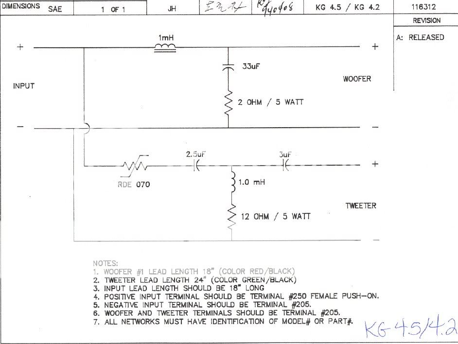
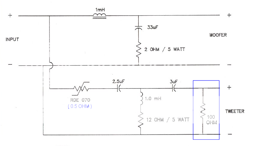
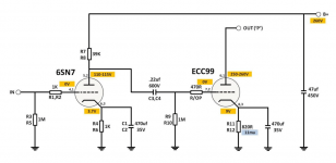
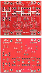
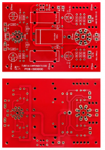
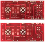
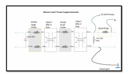
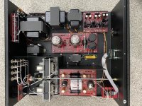
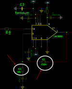
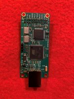
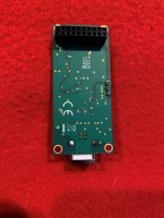
Schematic and pcb screenshot post #1 , plenty of pictures after .

Tips and Tricks thread - will open, sooner or later

Reading entire thread is advisable , same as inquiring any technical question there : Be sure that you are aware of all things electrical and mechanical !


Pcbs are made for UMS , mounting directly to heatsink


Do not hurry - read , think , ask and only when you feel that you want it and can make it , proceed ...... advice which I'm finding applicable on practically anything .

For anything else , write either here , send PM or directly to >zenmodiyaudio@gmail.com<

Prices are mostly dictated with small scale nature of operation (as always is case) and time/work involved in matching and soldering little buggers.

For ordering , contact me at above written e-mail addy .


edit on 27.11.2021. : pcbs changed for easier LU mounting; see (see post #620)


Kit options :

Option 1.
- LCH pcb ,
- RCH pcb ,
- all smd buffer JFets (Toshiba 2SK2145BL) presoldered ,
- smd precision CCS chips presoldered
- all smd caps and resistors presoldered ,
- 4pcs of 1uF MKC caps (for important bypass positions) enclosed.
-pair of small Daughter boards for LU (see post #620)
-mica for BD cascodes heatsink mount

Full price , including Paypal fee and P&P for registered shipping all around the Globe - 135E

Option 2.
- LCH pcb ,
- RCH pcb ,
- all smd buffer JFets (Toshiba 2SK2145BL) presoldered ,
- smd precision CCS chips presoldered
- all smd caps and resistors presoldered ,
- 4pcs of 1uF MKC caps (for important bypass positions) enclosed.
-all multiturn trimpots
-output mosfets , 2 pairs , IRFP240 & IRFP9140
-IRF510 & BD 139 - source follower/level shifter duty
-cascode bjts
-optocouplers
-all electrolytic caps (all Panasonics ,except Elna Silmic II for one signal route position)
-one-pin sockets for special resistor positions
-all (MF 600mW) resistors
-T0220 heatsinks - 6pcs
-pair of small Daughter boards for LU (see post #620)
-mica for BD cascodes heatsink mount
-etc.

to recapitulate - everything what goes on pcbs , excluding signal xformers and pcb/mosfet mounting screws/nuts/washers ; also excluding LU1014**

Full price , including Paypal fee and P&P for registered shipping all around the Globe - 185E


**LU1014 - in this moment I have quantity for, say, 35 kits; ask for them - tested and Ids matched, if you don't have them already; matched pair ( you'll get them soldered to Al boards) is 8E


If I have everything in drawers in moment of order , can ship in a week time;
If I don't have any of normal parts in drawer , shipping could be delayed up to 3 days;
If I don't have pcbs in drawer , shipping could be delayed up to 2 weeks;
If I don't have most critical part for getting in my neck of wood - CCS precision chips , shipping could be delayed up to 3 weeks.
All in all - you all know that ZM is slow, but inevitable

Handy Addendum (in short : HA!):

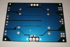
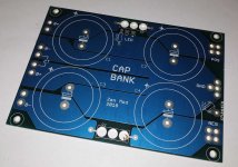
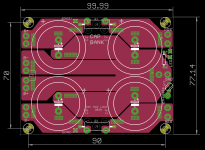
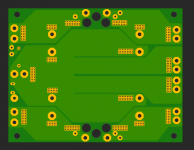
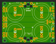
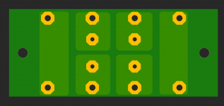
-Cap Bank pcbs - set of 2pcs; dual rail, CRC (pads, if you want differential CLC), snap-in up to 35mm Dia, resistor and pads for LED, position for 10mm NTC connecting Audio GND to chassis;
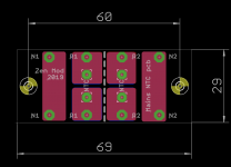
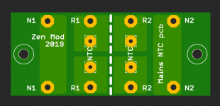
-NTC pcb/ FW style Soft Start - set of 2pcs; each having place for 2 independent NTCs;depending of arrangement of primaries of Donuts you're using. you'll need either one pcb for two Donuts, or one pcb per Donut

HA! set is 25E more

see pics for HA!; lazy to search do I have photo of NTC pcb, but who cares

Attachments

  • PSU pcb bottom.jpg
    PSU pcb bottom.jpg
    58.1 KB · Views: 1,413
  • PSU pcb top.jpg
    PSU pcb top.jpg
    86.1 KB · Views: 1,407
  • CB top eagle sshot.png
    CB top eagle sshot.png
    54 KB · Views: 1,401
  • CB bottom render.png
    CB bottom render.png
    88.7 KB · Views: 1,398
  • CB top render.png
    CB top render.png
    160.1 KB · Views: 1,382
  • eagle sshot.png
    eagle sshot.png
    17.4 KB · Views: 272
  • bottom render.png
    bottom render.png
    18.5 KB · Views: 244
  • top render.png
    top render.png
    38.4 KB · Views: 220

Cinemag transformer placement; before or after the attenuator?

Hi, all.

I'm finally starting to build my LM3875 integrated Gainclone based on the AudioSector boards I purchased some years ago.

I also got a set of Cinemag line transformers that are designed to sit in the signal chain at the inputs.

My question is that if I'm setting the amp up as an integrated amp, with a 50K stereo shunt attenuator, where should the transformers be placed?

The positions that come to mind are: 1) in-between the attenuator and the amplifier boards (so behind the attenuator, but in front of the amp boards), or 2) behind the source selector, but before the attenuator (so after the output of the source selector and before the input of the attenuator).

What it boils down to is should the transformers be placed before or after the attenuator?

Thanks for your help!

EL84 PP output + power transformers

SOLD: EL84 PP output + power transformers

Hello,

I bought these transformers a while ago for a project to build an Audio Note L1 amplifier, but never used them finally. They've been sitting unused for too much time so the times has come to let them go to someone else.
They were built by a famous Hungarian transformer builder. The only information I could find in my papers is that it has been built on SM77. I am not a professional, I assume this refers to the power transformer. Other information I know about is that he is using German iron cores only.

What you can see on the paper:

OUTPUT TRANSFORMERS
Grey = A1
Brown = A2
Blue-White = UL A1
Brown-White = UL A2
Lila (thin) = Ut+
Seconder
Black-Lila = 6 ohm

POWER TRANSFORMER
Brown-Black = 230V / 50Hz
Seconders
Red-White = 250V Anode
Lila-Lila = 6.5V Heater


Transformers are located in Budapest, but I am happy to pack them very safely and ship them anywhere in the World.

Weight of 1 output transformer is 2.6kg, while the power transformer is 3.8kg, therefore shipping fee would be around 30-45 euros within Europe, depending on the country of destination.

My asking price for all 3 transformers is EUR 220 plus shipping.

3jSBPFv.jpg

jMPly7G.jpg

H2lTtkc.jpg

f87sqfp.jpg

boonton 1130 help

Sorry new guy here never used a boonton 1130 before yes just purchased one on ebay. I have the manual for it but maybe i am missing something. I turn the unit on and I get [] on analyzer display and [] on freq display program states 99 ( which I know is the inital program. So what I wanted to know is just the basics. I press dist and I get nothing I have a 1000khz signal connected to the the high input and it never registers it? If this is too open ended of a post just tell me to pound sand and go " read the fine manual" again 🙂


Frank

Searching for a horn for JBL2425

I am looking to use my JBL2425 from 1kHz. 12dB slope. I will be using my flea amps, so no danger of damaging the driver even with only a 12dB slope.

There are many horns in that range, but I wonder if there is any benefit from using an over size horn? There are some horns with 1" entrances that go down to 500Hz, quite a few 800Hz.
I would still XO at 1kHz even if the horn cutoff is lower.
Any comments?

Any suggestions for a horn for this driver?

Ditto about a diy (wood) horn?

Thanks

Preamp Noise Issue

Hello all, I recently finished building a preamp kit from ANK but I had some noise (sounds very much like white noise) from it. I have checked all my steps/wiring and have confirmed these with Brian from ANK including all voltage measurements. So I would assume I built it correctly at least...

Here are my findings:
1. When I shorted the grid of 6SN7 to ground, the noise did not change. DC and AC voltage here to ground is 0V.
2. When I shorted the grid of ecc99 to ground, the noise disappeared. DC and AC voltage here to ground is 0.1-0.2V.
3. The noise appears after the preamp is on about 10 seconds.
4. The noise disappears after the preamp is off after 15-20 seconds.
5. It does not sound like hum or buzz, very much like white noise (something below 2kHz I would assume).
6. Both channels have the same amount/type of noise.
7. All the results above are tested with shorted inputs and I have done 1/2 on both channels. Noise disappears only at one channel at a time.
8. I tried more than three equivalent sets of tubes for each position, including ecc99, 6sn7, 5u4g. The noise does not change at all..
9. The noise does not change by the time it is tested. Actually it was tested in a room free of electronics and wifi even...

So I would assume the noise came from 6SN7. Then I tried some different tubes equivalent to 6SN7, the noise didn't change at all. In this case, maybe the noise comes from B+ or filament? Since other people who have built this kit have no hum/buzz/noise issues at all, I don't think it has grounding/design issues that caused my problem. Maybe it is a bad component, like a bad cap, a bad choke, etc. I need to find out which one is the bad guy...

If you have any thoughts, please let me know. I currently have a cheap scope bought from amazon, but it does not help much. When I shorted the grid of ECC99, I hear no noise. However, the scope shows no difference compared to not shorting anything and has noise.

Thank you guys very much! Here are some info about my preamp.

Attachments

  • Preamp Circuit.png
    Preamp Circuit.png
    201.1 KB · Views: 374
  • Preamp Fialment Board.png
    Preamp Fialment Board.png
    975.3 KB · Views: 357
  • Preamp Line Board.png
    Preamp Line Board.png
    690.8 KB · Views: 297
  • Preamp Power Board.jpg
    Preamp Power Board.jpg
    91.2 KB · Views: 325
  • PREAMP POWER SUPPLY.png
    PREAMP POWER SUPPLY.png
    83 KB · Views: 333
  • Preamp.jpg
    Preamp.jpg
    312 KB · Views: 263

DIY 2 Way Speaker Design Thoughts

Hello, over the past couple of days, I have been looking to design and build a speaker. The drivers I am using in my design are the following:
1x Dayton RST28F-4 Tweeter Dayton Audio - RST28F-4 1-1/8" Reference Series Fabric Dome Tweeter 4 Ohm
2x Dayton DC130A-8 Woofers Dayton Audio - DC130A-8 5-1/4" Classic Woofer Speaker 8 Ohm

The cabinet would be ~.92 cubic feet tuned to 60 hz.
The following pictures are the crossover design, SPL graph, and all graphs listed in VirtuixCAD.
I am wondering if you have any thoughts about the crossover design. Here are a couple of questions I have.

Should the 3db dip around 4600hz be any cause for concern?

I've read about baffle step / diffraction, do you think this would cause issues?

When building a crossover, does the type of capacitor matter (poly vs NPE)?

Calculating the total cost to build this speaker and cabinet came out to ~$350. Would this speaker be worth the money compared to retail speakers assuming the finish was equally as good?(I enjoy building so that part wouldn't be considered a chore, also I know there are a lot of factors affecting this but more of a general question if the speaker came out close to the simulation)


3e10b69d8257697acd1a8701320a52be.png

bd11b14175bf2a1a42df58f25a2da581.png

057b0545515782bab8792e7ae172c441.png

The XCEN -- Balanced to Single Ended Converter

Joachim Gerhard & I had some discussions here about a balanced to single ended converter :
http://www.diyaudio.com/forums/digi...minimalistic-iv-converter-21.html#post3097491
(up to post #1052)

I renamed it XCEN, as X (balanced or differential) is converted to C (single ended complementary).

The previous version (2C) still uses 2SK170/2SJ74 which are now difficult to get.
So I tried another version by just replacing the 2SK170/2SJ74s with 2SK246/2SJ103.
Performance is still very decent. So good news as the latter are still relatively easy to get.

PCB for this latest version will follow. To be continued.

🙂


Patrick

Attachments

  • XCEN BAL_SE Converter V2c Sch.png
    XCEN BAL_SE Converter V2c Sch.png
    41.4 KB · Views: 3,360
  • XCEN BAL_SE Converter V4  FFT.png
    XCEN BAL_SE Converter V4 FFT.png
    43.2 KB · Views: 3,238
  • XCEN BAL_SE Converter V4  Freq.png
    XCEN BAL_SE Converter V4 Freq.png
    55.1 KB · Views: 3,048

WTB: Hypex DLCP

Morning all,

After years of wanting a DLCP I finally bought one.... which turns out not to work. A bit frustrating but there we go.

I know it's very old but if anyone has one laying around that they're looking to get rid of please give me a shout.

If you did this post up in 2022 please still respond... I bought mine in 2020 and didn't try to use it until 2021... that' the rate I work at, and it doesn't seem there's many of these around!

Equally, if you have recommendations for an alternative I could try (2 in 6 out dsp with usb and spdif) please let me know.

ProAc Super Tower 1st edition blowing tweeters

Looking to get some confirmation on the crossover cap values in the original Super Towers. My friend's already fried the original MB Quart tweeters and has subsequently fried the Morel MDT 30S's recommended by Madisound.

In the HF section there are two large Solen radial caps that are clearly not original, one is 4.7uF and the other is 15uF. From what I've read about the Studio 1, which uses the same drivers in single-woofer bookshelf format, the crossover point should be 2.5kHz and both HF crossover caps should be 4.7uF. The 15uF cap would lower the crossover frequency, and my tests with a mic show the tweeter is passing signal down to 1kHz. That can't be right since the original MB Quart MCD25M is only rated down to 2kHz.

So as I'm borrowing one 4.7uF cap from one speaker to replace the 15uF cap in the other for testing, if anyone has any intel on the proper cap values I'd feel more comfy because my friend will wantonly unleash his Hafler DH220 on these puppies upon their return.

first time 3 way visaton build

hey guys

this will be my first build so got a lot to learn

im certainly no audiophile but i do like my music ranging from classical to a bit of r&b some 80's and a bit of dance stuff
id like to start with building two front speakers which will also be used in my home cinema setup

the amp i have is an old Denon AVR-2807 (7x110w) which will do for now , im sure underpowered for the below mentioned that i wish to run , but this will be upgraded in due time

Visaton TIW 250 XS, 8 ohm, 10 inch
Visaton AL 130, 8 ohm, 6 inch
Visaton KE 25 SC, 8 ohm, voice coil 25 mm

3-way crossover Visaton HW 3/130, 8 ohm, 300 / 4000 Hz

what i wish to do is get components that i can still use even if i add to the system . i dont want to have to buy new components each time i 'upgrade'

so the above mentioned items , if i want lower bass then i will prolly go with a single 15" however this is highly unlikely as im sure i will be disturbing the peace , i think for some effects a transducer in the sofa will have to suffice if want a bit more booom

with regards to the enclosures , i really dont want a square box look and would like to do an enclosure with some curves , as i work with composites im sure there will be some carbon touches here and there

so down to the enclosure design ... if i stick to manufacturer recommendations on volume , how important are the proportions ?

i wish to do a slight taper on the uprights but still keep the volume the same obviously

the attached speaker enclosure is v1 and im sure it will change many times before i start the build , but its a start

Attachments

  • clifford.jpg
    clifford.jpg
    115.2 KB · Views: 435

Are there any free resources to understand Bose's philosphy of sound production?

I heard that Bose's approach to sound production is different from all the other companies, Bose focuses more on the psychoacoustics than technical accuracy of the equipment. That is why it doesn't publish specifications of it's speakers and most of them are not within +/-3dB. But many people regard them as pioneers in speaker making, it seems like Bose forgoes on the quality of the transducers and uses cheap transducers but uses DSP to make them sound good.


I want to know more about this psychoacoustics philosophy to sound production, are there any free or paid resources to understand it?

Help connecting preamp to amp.

Hello Everyone,


I am just venturing into the audio DIY world, looks like its an amazing ride.

Seems I have hit my first issue already - cant seem to get my preamp and amp to work from the same power source.


Preamp - XH-A901 - NE5532 (with a rectifier at power supply) - InkOcean XH-A901 NE5532 Digital Power Amplifier preamp Tone Board HiFi Fever Grade high and Low bass Adjustment Tuning Board preamp Board : Amazon.in: Electronics

Amplifier - XH-M510 - TDA7498 - Triupy XH-M510 TDA7498 High Power Digital Amplifier Board Car Amplifier : Amazon.in: Electronics

SMPS - LRS-200-24 - Amazon.in: Buy Meanwell Switching Power Supply LRS-200-24 AC-DC 24V 8.8A 90 132VAC 180 264VAC by Switch Mean Well LRS Series Transformer 24VDC Online at Low Prices in India | MEANWELL Reviews & Ratings


Setup - audio source > XH-A901 > XH-M510 > Speakers

The setup works only if the preamp is powered separately, with another SMPS.


Tried bypassing the rectifier on preamp, since it was receiving DC already, but no luck.

Should I have a common ground for both boards or something on those lines?


Pretty sure I might have got something basic wrong in here, hope you guys can point me at the right fix?


Thanks in advance!


Also happen to have a 6J1 tube preamp (AC 12v) Fever 6J1 tube preamp amplifier board Pre-amp Headphone amp 6J1 valve preamp bile buffer diy kits : Amazon.in: Electronics, was planning to put this in to the above setup as an optional preamp - like switch between the 6J1 and NE5532 preamp with a rotary selector.

Soundstream Reference 700s Auto current circuit

I've seen several S/SX Soundstream amps with damaged boards around blown MPS8099/MPS8599 (Q59/Q56/Q55) which is part of the auto high-current circuit. Now this particular amp will actually power and play but the amp is stuck in high current. Obvious board damage etc. I can cut out and repair this but...

Why does this even happen? Is there a modification I can do to help hold the circuit from failing? I dont see any other issues with this amp at this time.

LTspice and PSUD , never the twain . . . . . .

I find I have very poor luck with LTspice , no matter what I try to reduce the wandering lack of regulation - going to more filter sections , mixing RC with LC , changing values , I can't seem to eliminate the wandering irregular ripple.

OR . . . Is it that PSUD is lying to me and it's not going to be as easy to do things the way I like.

But for the diodes (no 1N4007 in LTspice - Highest Voltage Rated diode is 800) both sims are using identical values . Any instructive critiques? Most welcome if you have them !

Thanks !

Attachments

  • In LT.png
    In LT.png
    69.3 KB · Views: 145
  • In PSUD.png
    In PSUD.png
    109.7 KB · Views: 136

NAD C272 refresh

Hi Guys!

I was out to buy some used speakers from a local guy and got a NAD C272 and a AKAI AM-55 amp with it.
Both very dirty but in working condition.

I like to use the NAD as additional amp for my stereo setup, so I'll take care of the AKAI later.


I'm by far no electronics expert, but it should be fair enough to refresh worn parts, check components/circuits, follow schematics etc.
At least for this aged amps.
So please forgive me some stupid questions, and that I don't understand everything immediately.


I've opened the case and cleaned the inside with compressed air and
found very dirty nicotine caked PCB's and components.
The pre owner must be a chain smoker... :ashamed:
I've checked the amp on the bench and found only a scratching line in pot.
Apart from the higher cleaning effort it should be worth a refresh/rebuild.
Well it is 15 years old but should be still a good sounding amp.


This is my todo list so far:
Clean every PCB/components
Renew all electrolytic caps
Renew line in pot.
Renew all Trimpot's
Renew all sliding switches
Renew speaker/standby relays
Renew standby switch


Because nicotine goes everywhere inside of components I added the sliding switches and relays to the list.
I want to refresh the amp so that it should last for another 10-15 years.
Is there anything else that i should add to the list under this aspect?
Maybe rectifiers, regulators, diodes?
At first my thoughts was to replace every part which are under heavy thermal load which accelerates aging.
Especialy some of the 2/3W resistors get very hot. But also the 2SA872A/2SC1775A transistors on the R/L amp boards has left heat tracks on the PCB.
I have no experience with aging or accelerated aging of semis etc. and I'm grateful for every advice.
I know it's hard to find low noise substitutes for such semis with right/matching hFE.
But if its woth it I'll go for it.


I looked already for replacements PSU caps which seems not easy to find.
Maximum diameter is about 35mm for a 10000uF 100V 105°C snap in cap.
40mm will not fit.
NAD changed the caps from 80V to 100V after a few was blown.
The shematic shows still 80V
NAD has spare parts, but they want 65€ per cap. 😱
So far I only found chineese copys/fakes on aliexpress etc which would fit.
The PSU board has space/holes for 6 caps but only 4 are fitted.
Before I'll get fake/copy caps i'd rather use 6 smal caps of 6700uF caps which i could get with good quality.

Maybe someone has a source for good genuine 35x max ~110mm long caps with 10000uF 100V 105°C?


You can find the Service Manual on Vintageshifi


https://www.vintageshifi.com/repertoire-pdf/pdf/telecharge.php?pdf=Nad-C-272-Service-Manual.pdf

Amanero USB (Twisted Pear Cronus programming)

I have two others and don't need this one. Programmed for Twisted Pear use. Just tested and is working fine on the Cronus/Hermes combination.

Includes Amanero card ONLY.

$65 includes shipping to contiguous USA Only.

Payment via Paypal friends/family required before shipping.

Attachments

  • 5.jpg
    5.jpg
    680.9 KB · Views: 192
  • 4.jpg
    4.jpg
    409.5 KB · Views: 187
  • 6.jpg
    6.jpg
    514.3 KB · Views: 176

A Speaker that Kicks Butt in Large Spaces

I originally posted this in the KARLSON thread, but figured there might be some general interest from folks who normally don't read about the Karlson.

The cool thing about having models of various speakers is that it lets you do desktop comparos of the same driver in different cabinets, in different settings from the comfort of your latop (while riding a bus in my case). Details of my AkAbak model of the Karlson K15 speaker can be found here: http://www.diyaudio.com/forums/full-range/213594-karlson-10.html#post3528706

I noticed that many of the pictures of the Karlson show it in a large venue (stage, night club, dance floor, etc.) and I figured there must be something that might make the Karlson special for such occasions.

So I am taking one of my favorite deep bass extension MLTL designs that is flat as board and running it head to head with a Karlson. What I found surprised me.

Basically, if you are in smaller space like a room in a house, the MLTL is a great design as it lets you put the speaker right up against the wall. The first plot is the Betsy K in a 45 in tall MLTL (11 in wide x 16 in deep x 1.625 in tall x 11 wide x 4 in deep port at bottom, driver 9 in from top), speaker cabinet is flush against a wall and listening position is 1 m away. This is perhaps one the nicest frequency response curves I have of ANY design I have simulated and is consistent with Bjohanessen's WIBAQ.

Next plot, place a K15 with Betsy K flush against a wall and listen 1 m away and it really sucks. Very uneven frequency response.

Third plot, let's put the speakers away from the wall at 60 in and stand 5 m away from the speaker - something similar to how speakers might be used in a PA setting like a wedding. The Betsy K MLTL doesn't look so good anymore, bass has dropped and response overall very uneven. Most importantly, the ever important 50 to 60 Hz bass region that provides a lot dynamic punch is almost all but gone (75 dB) and peak bass has shifted to 90 Hz and is only 85 dB.

Fourth plot, put the K15 with Betsy K at 60 in from wall and listen 5 meters away. Notice the sound level is about 90 dB at 5 meters away. The response also has a pretty flat bass shelf to give a nice clean tight punch to the bass notes from 60 Hz to 100 Hz. Now that is something special! I don't know of another speaker with a $55 driver that can throw that kind of bass that far with 1 watt input!

Fifth plot, if I tweak the K15 cabinet by elongating it in the vertical direction by 1.33x and widen it by 1.07x, and enlarge the 21.5 sq in vent by 1.5x, we get a 5 Hz deeper bass extension to 55 Hz a flat bass shelf, and a nice response.

6th plot shows the polar SPL response at 5 m away for the MLTL at 60 in from wall, for 60 Hz, 200 Hz, and 500 Hz. The response is not very goo at all.

7th plot shows the polar SPL response at 5 m away for the original K15 at 5 m away for the same frequencies. Notice how close together the responses are over a pretty wide sweet spot.

So, in conclusion, every speaker has its ideal use and 'home'. The Karlson is at home on stage and should be seriously considered for a large room where volume and bass punch is important. You won't get ultimate deep 30 Hz bass like a MLTL, but you will get a nice reach with 50 to 60 Hz at butt kicking levels, with great spatial coverage and uniformity.

Attachments

  • Betsy-MLTL-1m-flush-wall.png
    Betsy-MLTL-1m-flush-wall.png
    19.3 KB · Views: 14,385
  • K15-1954-Original-Betsy-1m-flush-wall.png
    K15-1954-Original-Betsy-1m-flush-wall.png
    29.1 KB · Views: 14,209
  • Betsy-MLTL-60in-wall-5m.png
    Betsy-MLTL-60in-wall-5m.png
    30.2 KB · Views: 14,057
  • K15-1954-Original-Betsy-5m-60in-wall.png
    K15-1954-Original-Betsy-5m-60in-wall.png
    26.8 KB · Views: 13,942
  • K15-1954-Stretched-Betsy-5m-60in-wall.png
    K15-1954-Stretched-Betsy-5m-60in-wall.png
    27.2 KB · Views: 13,859
  • Betsy-MLTL-60in-wall-5m-Polar.png
    Betsy-MLTL-60in-wall-5m-Polar.png
    19.6 KB · Views: 1,011
  • K15-1954-Original-Betsy-5m-60in-wall-Polar.png
    K15-1954-Original-Betsy-5m-60in-wall-Polar.png
    22.4 KB · Views: 874

Question for engineers about enclosure stiffness

Hi all,

I was wondering if a hollow cube or rectangular prism (like speaker enclosure) made of MDF or HDF walls of sufficiently high thickness, would at a certain minimum thickness show no measurable benefit from internal bracing regardless of frequency range and typical SPL requirements?

Thickness would be proportional to box size.

Assume there is a sub woofer in the enclosure.

OTL Headphone Amp as Preamp?

Is there any technical reason (aside from maybe too much gain) as to why an OTL tube headphone amplifier cannot work equally as well as a stereo preamplifier? The amplifier in question has a 22.1 kOhms input impedance which, while lowish, should be plenty high enough in this case. This OTL preamp uses 6H30 output tubes. I suppose the concerns *could* be running the signal through a capacitor (I'm assuming this is a cathode follower) and perhaps the circuit uses a prodigious amount of negative feedback, although honestly neither concerns me technically ...

Push-Pull 2 x 2000 Ohm Loudspeaker for OTL

Just something that might be interesting and new to some. Not sure if it belongs to the Full Range speaker section. It's a bit unique (or is it?).

In 1957 Philips experimented with a loudspeaker with a voice coil of 4000 Ohm with a centre tap, driven OTL by 2 x UL41 in push-pull. For that they modified their 9754M loudspeaker. They even equiped a number of Philips BX521U radios with this arrangement. These radios are very rare now. I never saw a schematic of it.

In the attached article from 1957 the results were described as rather positive (improved reproduction of the low notes), although only class A operation was possible. But in this Philips book from 1965 it was described as "...not a great success..." beacuse of the coupling between the halves of the voice coil being too loose (see halfway page 15): http://www.introni.it/pdf/Rodenhuis%20-%20HiFi%20Circuits.pdf

The 9754M speakers in pictures 1 and 2 are not of the push-pull kind but just for reference. The 9754M in the third picture is of the push-pull kind.

The purpose of the 'dustcover' is not so much to keep dust out but to dampen of the lower resonance frequency of the speaker (with about 6 dB).

Attachments

  • Philips 9754M a.jpg
    Philips 9754M a.jpg
    302.9 KB · Views: 97
  • Philips 9754M b.jpg
    Philips 9754M b.jpg
    360.3 KB · Views: 105
  • Philips BX521U equiped with the push-pull version of the 9754 loudspeaker.jpg
    Philips BX521U equiped with the push-pull version of the 9754 loudspeaker.jpg
    55.5 KB · Views: 102
  • PTechReview-19-1957_58-041.pdf
    PTechReview-19-1957_58-041.pdf
    787.9 KB · Views: 76

Altec - B811

I am selling a nice set of Altec 811B Horns without driver.

These are nicely painted (if you like the color) and
do not exhibit any scratches.

I can send more images, if anybody needs them.

Price:

450$ or 400€ - excluding postage + paypal fees ( 5%)

Shipment we'd need to discuss. If you're serious about a deal I'd be happy to look up shipment fees, terms and conditions.

I am located in Düsseldorf/Germany. It would make the whole deal a lot cheaper for you if you'd live close by to pick them up.

Attachments

  • Altec-811B-09122021.jpg
    Altec-811B-09122021.jpg
    606.5 KB · Views: 221

SOAP MKIII (Simple OpAmp Pre) With onboard PSU

Just thought i should share this with you guys.

Made a new layout for the "SOAP" preamp and added a regulated (LM3x7) supply onboard.

Another difference is that In and Out is on the same sid of the PCB and that should make it a little easier when putting it in a chassi.

It has been tested with very good result.! 🙂

No hum, hiss or noise. Completly deadsilent background.
Sound is powerful and clean and it does a very good job.


If you want to etch yourself, Be my guest 😉


An externally hosted image should be here but it was not working when we last tested it.


Prototype

An externally hosted image should be here but it was not working when we last tested it.


Sche
Silk
Copper
Overview
BOM

Regards

/JZ

LX521.4 without woofers

I made these 2 years ago and listened them very rarely. They have total less than 400 hours in them so just broken in. Everything measures and sounds as it should.

The top baffle is 4 layer sandwich of Alu-Plywood-Alu-Plywood. The top baffle stand is CNC machined Alu and it is adjustable. The speakers do not have proper binding post terminals as you can see in the photos.

I have already sold the woofers (incl frames) but still have the main speakers
(top part) and the bridge.

Price is 350 EUR + shipping

I can ship these to almost anywhere, just ask for shipping quote.

I will take some better photos, but here is a teaser =)

Attachments

  • 20190407_090357.jpg
    20190407_090357.jpg
    1,020.6 KB · Views: 338
  • 20190407_090419.jpg
    20190407_090419.jpg
    997.4 KB · Views: 331
  • 20190407_090444.jpg
    20190407_090444.jpg
    744.2 KB · Views: 340
  • 20190407_090645.jpg
    20190407_090645.jpg
    990.8 KB · Views: 331

Taramps power supply

Hey guys got a taramps MD8000 1 ohm model here that has a smoked power supply (output is fine)

I can see it's blown the buffer chips. But I can not read what the part number.
Suspect IC is 'IC3'. The other side of the board seems in better condition but I can not find any other chip with the same numbers as I can make out on the burned IC.

Here are a couple of photos.
One of the burned chip and 1 of the other ICs that are similar.

Cheers guys

Attachments

  • 20210811_152012.jpg
    20210811_152012.jpg
    686.2 KB · Views: 173
  • 20210811_152123.jpg
    20210811_152123.jpg
    635.4 KB · Views: 171

Revox B760 w. Amnesia

Guys, is there a ReVox B760 tuner expert in the room? Mine is suffering from advanced Amnesia, it just evaporates station memory. When not used for months, after power on, I can program some stations which it will keep for few days. After that they are gone, and cannot be re-programmed at that time. Putting it away for some months, it seems to recover and allows to be programmed. For a day or what..

Familiar with this, please let me know (guess I need some new memory board/chip of some kind..) Voltages are OK, I remember I measured.

The sticky (yes, that awful paint) bastard is of no use right now..

Leonard

LG S55A1-D Subwoofer cabinet design plans

I recently bought a 6'' LGZ40 subwoofer form a local shop, it has following information printed on the back of its magnet.
LG Electronics
EAB6368703
LGZ40
EC150L01
7B23A

Having these pieces of information and power of Google, i was able to find three online seller listings for this same model of subwoofer, one of them being an AliExpress one, the seller is selling it under the brand name of GHXAMP but its actually a LG product.
Listings are as follows:
GHXAMP 5.5 / 6 inch Pure Subwoofer Woofer Speakers Rubber Edge 30 Core BASS Pots 4OHM 60W 120W 1PCS|subwoofer woofer|woofer speakerspeaker rubber - AliExpress
Google Translate
Google Translate
One of the seller(polish one) mentioned that it was pulled out from a LG S55A1-D subwoofer and i confirmed his claim by checking through LG's
websites
LG LAS551H | WiFi Audio| Sound Bar | LG Electronics Canada
Although i was able to find this much of information, unfortunately i couldn't find the T/S parameter for this subwoofer anyware on internet, so i decided to go with LG's design of the cabinet that it originally came with, but couldn't find the plans on internet. Anyone knowing knowing T/S parameters fo this model or having LG S55A1-D Subwoofer cabinet design plans can help.

sub-woofer with vibration speaker

hi
suppose if i build a small enclosure using Tang Band W2-2040S 2" RBM Micro Subwoofer 4 Ohm and cross this with a Dayton Audio BCE-1 22 x 14mm Bone Conducting Exciter, will there be any problems with the sub, even if it is separated by two diff sections?

since i am planning a portable stereo unit, i can use two of these exciters with a single sub, right?

can such an arrangement work?

Measuring onboard resistors…

Today, after a few glitches during a build, I realized I‘d better be cautious and measure all resistors already on board (I messed up more than once, how many more are there?)

Off I went, comparing schematic and board, and double checked every single resistor.

Oddly, some results are spot-on or within 1%, but some others are off, like, 30% below the value. I don’t get it, is that normal?

All resistors were confirmed before populating the board with my DMM…

My 833-A amplifier

I have completed and perfected my magnum opus, an 833-A single ended triode amplifier which drives a pair of Magnepan 0.7's. It is one and a half years in the making. I am interested in guiding anyone who would like to use this wonderful triode which I consider the Stradivari of vacuum tubes for music. It works best at 1000 Volts with zero grid bias where on the chart it is just as linear as it is at any other voltages, something I verified by using batteries to test both positive and negative bias applied to the grid which had the effect of symmetrical changes in plate current with respect to grid voltage, +1.5 Volts raised the plate current by 8 ma and -1.5 Volts lowered it by 8 ma. It sounds best at zero grid bias which causes the tube to draw 110 ma.

It costs well under $2000 to build a pair of these and it uses Hammond 1642SE output transformers rated to carry 300ma pot tested to 4kV. I drive it with Lundahl LL2765 transformers to step down from about 5k to 500 Ohms on the grids. The 1000Volt plate supply is straight forward with proper caging for safety and fuses on the power transformers and the 833-A cathode requires a very well filtered 10 Volts DC at 10 Amps for which I use 4.5 Farad filter capacitors which pre-charge before turning it on.

Attachments

  • CF44EE0F-F746-4BDF-AE39-376E487D8C7B.png
    CF44EE0F-F746-4BDF-AE39-376E487D8C7B.png
    860.1 KB · Views: 1,069

Help with Hurst motor

I just ordered a new Hurst motor (3203-001) for a VPI HW-19 clone but the noise/vibration is terrible. Since Hurst does not take returns (shame on them) how can I reduce the noise? Unlike the motor for the AR, where you can adjust the shaft "slop" by tapping the rotor/shaft bushing tighter to reduce the endplay, this looks like it has a wavy washer/snap ring? Also the there is slop between the outer cover and top plate, where a rubber washer/o-ring is in the gap between the two. Mine is loose.
I used to use this motor a lot in the past. Now that these are built in China, the quality is very poor. Sucks that a non-returnable $100 motor is this bad.

Ultimate turntable design: modern technology to remediate root cause issues

Over the past 10 years, I have designed/rebuilt 3 different turntables. Prior to that I owned Rockport Capella II and Brinkmann Balanced turntables. Yet, in the quest for a great table, none of my efforts nor purchases have resulted in great pleasure.

So, I ask you to join me on this journey to theoretically technology for a world class, dare I say nearly perfect turntable. So, here are few thoughts:

Assumptions

1. cost no object
2. simplicity wins the day
3. tonearm and cartridge are not considered in this design


Goal
A. Constant speed
B. elimination of mechanical noise transmitted to stylus

When you think about it, a turntable really does 1 thing: spins an LP. Taking this a step further, spinning an LP at the proper speed. Taking this further further, spinning an LP at proper, constant speed. Finally, spinning an LP at proper, constant speed without mechanical/electrical noise transmitted to the stylus.

In today's world, nothing is perfect. So, turntable designers work to mitigate issues associated with constant speed, noise, etc. Damping, isolation, motors, bearings, plinths, etc. all are an attempt to mitigate the impact of root causes. So, why don't we attack the root cause issues and avoid the need for mitigation.

To this end, let's break this down into 2 basic functions:
1. platter speed accuracy, resolution and constancy
2. noise avoidance (mechanical or electrical)

Addressing the first item (speed). Depending upon which drive technology is used, we get different root causes. Take for example, idler drive. We know that idler wheels are not perfectly circular. Nor are the rims that interface with the idlers. At best, the rubber idler wheels likely are +/- 0.0005". Over time, the idler wheels wear/tear and the circularity is degraded. This leads to speed fluctuations, wow/flutter, etc. Belt technology is hamstrung by the belt itself. It flexes, stretches, wears, gets dirts, slips. This in itself leads to speed instability. Finally, direct drive. Theoretically, this appears to be the final frontier with one large assumption: sufficient motor control and drive technology. 50 years have passed since the advent of direct drive tables from the 1970s. And during this time, direct drive encoders, controllers, drives have all advanced to a point which we are able to create nano-technology solution that were not even a dream 50 years ago. So, maybe we should reconsider state-of-the-art direct drive rotary systems with sub-micron accuracy, resolution. Remember, cost no object and therefore, a direct drive rotary solution with ample control/drive would be state-of-the-art turntable drive capabilities, correct?

Secondly, noise. Once again, turntable manufacturers go thru hoops to remediate noise issues. Think about plinths, bearings (radial and thrust), platter, CLD, etc. What if we did not have mechanical noise at all? What if we relied upon state-of-the-art, world class air bearings used in the manufacturing and silicon wafer industries that have nano-precision, stability, stiffness? This is common technology that appears to be mostly overlooked by the audio community. Remember, cost no object. If we use an air bearing we have no, ziltch, nada, mechanical contact. Remember, our platter will float on a stiff airbearing, have no radial contact, no belt, no idler. Just a highest resolution, direct drive motor controlled with sub-micron accuracy, resolution.

Isn't this the final frontier based upon existing technology? Ultra precision direct drive with state-of-the-art air bearing. No need to worry about plinth, belts, idler wheels, etc. Just the platter floating on a stiff wafer of air spinning at highest precision, accuracy.

Here are some specification for the world class technology that we might apply to our theoretical ultimate turntable:

thrust bearing stiffness: 34N/um
Permissible torque in θx: 4.52 N·m
Moment of inertia in θZ, unloaded: 1780 kg·mm²
Drive torque clockwise in θZ: 0.86 N·m
Sensor signal: Sin/cos, 1 V peak-peak
Positioning accuracy in θZ: ± 8 µrad
Sensor resolution: 0.024 nm

The downside to this solution is that it is not simple. Air compressors, clean air purifiers add complexity while air bearings themselves are sensitive mechanical devices.

Yes, some manufacturers already use direct drive and air bearing technology. But are they using world class air bearings? World class direct drives? Please share your thoughts. Challenge the thinking and try to come up with alternative technology to surpass what is proposed.

Thanks!

Mixed cathode bias

Has anyone had good experience with mixed kinds of cathode bias? I'm thinking here of combining a resistor and a LED or SIC diode or similar. in my case it would be for an input stage. The goal would be to eliminate the cathode bypass capacitor by enabling the use of a smaller resistor like 100 ohms or even less if possible. An example is shown with a SIC diode. Ale discusses SIC diode bias on his Bartola Valves website.

I have tried pure SIC diode bias a few times and in the end preferred a resistor, but combining the two might give good results. I'll set up a comparison when I have time.

One question - does it matter if the SIC diode is above or below the resistor or is there no difference?

Attachments

  • mixed bias.png
    mixed bias.png
    41.6 KB · Views: 326
Projects by fanatics, for fanatics
Get answers and advice for everyone wanting to learn the art of audio.
Join the Community
507,648
Members
7,882,654
Messages

Filter

Forum Statistics

Threads
405,961
Messages
7,882,654
Members
507,648
Latest member
nguyenbatrinh