Voltage selector rare??

Anyone know where I can get one of these voltage selectors from? It has YKS11-0002 by JALCO on it.
I tried looking up the number but there's next to nothing about it and I think the company no longer exists?
It's out of a Pioneer A-656 Home theatre amplifier.
It's the only thing stopping it working "hopefully" everything else checks out fine as it doesn't look like it was set to 110v and plugged into 240v

Any help would be greatly appreciated 🙂
20230405_091504.jpg
20230405_091504.jpg
20230405_091359.jpg

Attachments

  • 1680651248802-359769668.jpg
    1680651248802-359769668.jpg
    199.3 KB · Views: 210
  • 20230405_091613.jpg
    20230405_091613.jpg
    430.3 KB · Views: 290

Recommend your favourite tools from Mouser

Never bought tools from Mouser before. Have a small electronics parts order, want to get my cart to $100 for free shipping!

The only think I am looking for specifically is a small adjustable wrench, rather than using needle nose pliers for tightening speaking binding posts and RCA jacks (the needle nose always slip and scratch the nuts)

What tools do you like?
Thanks!

Lomo germanium mic/line preamps + transformers

For sale Lomo germanium mic preamp card including original input microphone step up transformer 1:3.
This preamps were a part of Lomo 4ch powered mono mixer. Preamp itself contain 3 germanium transistors. It can be used as mic preamp with step up transformers or preamp for line level signals.
This quite interesting schematics, small amount of current flows to the base of the first transistor through the transformer's secondary winding. Approximately 2 microamps. It is enough to open transistor but not enough to magnetize transformer core. Honestly, this preamp sound great. Overall gain with step up transformer approx. 38-40dB.
One card and one transformer including shipping 55€.
2 sets including shipping 95€.
Have 8 pcs for sale.
Will ship worldwide.
Let me know if you have any questions.

Attachments

  • hkxtpawzlzj34icsc68h[2].jpg
    hkxtpawzlzj34icsc68h[2].jpg
    218.9 KB · Views: 342
  • ntbgwe3fzc9lz4wae6ab[1].jpg
    ntbgwe3fzc9lz4wae6ab[1].jpg
    274.6 KB · Views: 284
  • germanium card.jpg
    germanium card.jpg
    93.7 KB · Views: 280
  • gsyjgpugkxifjoopvcfc[1].jpg
    gsyjgpugkxifjoopvcfc[1].jpg
    203.9 KB · Views: 268

Carver MXR 130-Troubleshooting The AMP

Well, I recently purchased a MXR 130 that worked perfectly, nice shape, and it sounds incredible. So I thought I would purchase another to play with it. After reading all this, and other sites, I realize the Carvers are NOT the easy fix as the Sansui's I have been working on.

I replaced the relays, and it still is in protection mode I guess. Doing the first amp alignment procedure I did manage to get the voltage set right, but didn't have the dummy loads in place, so I am not sure if that makes a difference. I also broke the only small plastic screwdriver I had. So I got a new plastic screwdriver, still waiting on the dummy loads.

I did check the idling without the loads, and it's close, but also seems to wander. Waiting on better clips for my Fluke so I don't have any slips and fry me or the unit. I did notice on my working one, that the display does not show, on FM until the relays click in. So I think the second might be okay there because it does show it tuning.

I think I would be better off starting a new thread, and seek your assistance. Not in a hurry, just wanting to learn. I can check voltages okay, I just wish I didn't have to read multiple threads to get all that info, but then again, maybe little by little is the way to go. I have good soldering equipment, just some days my hand resembles that scene in Blazing Saddles.


Previously from anatech said:
QUOTE:
Hi Ciscoguy2,
Sooo ... why did you follow the thread here? Are you having a problem, if so what is it?

I was the Canadian Factory warranty for Carver. END QUOTE:

If I can, I would appreciate working with just one expert.

DIY Audio Enthusiast [very short] Survey

Dear members,
We are looking into ways to enable the DIY loudspeaker enthusiasts to focus better on their creativity while building even higher quality loudspeakers. To achieve this goal, I am doing research to get a better understanding of the needs of the DIY loudspeaker enthusiasts. I would appreciate it if you could fill in this very short survey.
Looking forward to your responses.
Thank you
  • Like
Reactions: Harry72 and Ciro82

Not So New Guy with a Question

Hey guys.

I've been lurking here for a few years and am finally getting started on a few audio projects.

I am starting out simple by building some JLH '69's and '96's in different configurations and with different semis, building some simple chip amps, building some full range speakers and hopefully getting some of my old Pioneer SX-3800's repaired.

My question: A long time ago I saw a post with a picture of an amp built with bare copper conductors kind of like this one of XRK971's:

https://www.diyaudio.com/community/threads/post-your-solid-state-pics-here.96192/post-4851050

(Hopefully shows post 4,879 in the solid state pics thread) and there was a link to a bunch more similar pics of "amp art". I have looked and looked and cannot find that thread/post. Can anybody point me in the right direction?

Hello and thanks,
JP.

Subwoofer hum paired with a Crown XLS 802 Power Amp

Hello diyAudio experts,

I'm experiencing a buzz/humming issue with a used Crown XLS 802 amp that I purchased($200) and a pair of Dayton Audio 12" subwoofers (RSS315HO-4). I'm using them in my home theater by connecting through the AVR's preamp outputs.

I've isolated the speaker-humming to either the (Crown amp/subs/rca's) because I disconnected any other components that might be causing the buzz. With Power ON and the 2 subs connected to the speaker outputs, as soon as I connect the RCA cables to my XLR>RCA adapter I begin to hear the buzzing. I've tried different RCA cables and even new ones but the buzzing remains and gets louder as I increase the gain. I expect this has something to do with a ground loop so I'm using an adapter plug on the end of the amp's power cable to eliminate the ground prong. The XLR>RCA adapter is the solder type, so I soldered XLR PIN 2 --> RCA's tip and PIN 1 --> RCA ground. XLR PIN 3 is not connected to anything. I also measured the DC Offset on both speaker output terminals and with nothing connected I'm getting readings in the 65 - 70 millivolt range. Not sure how much of a difference this makes but I hope that 65-70 mV is semi-acceptable and that I didn't purchase a lemon.

I welcome any suggestion to help eliminate this problem, I just want to be done with it....

For Sale Kenwood KX1030 3 Head Cassette Deck

In working condition. Pick up in the Napa Valley for $75.00 OBO

My brother in law spent about a months salary to buy this brand new in 1979 or 1980.
It has state of the art features at a time when cassette decks reached their pinnacle.

3 ferrite heads for live monitoring of recorded material
Fine Bias adjustment controls
DNR
Electronically controlled DC motor
Uses Type I, FeCr or CrO2 tapes
Frequency Response: 25Hz to 20kHz (Cr02 tape)

Audax TW034 replacement VC frustration

I'm swapping out some old and tired VCs from a pair of Auxax TW034s. Both the new dome assemblies buzz when swept with a sine wave @ 2.83V. The old ones worked ok before, except for showing signs of old age, so i thought it would be business as usual replacing them. Of course I cleaned and inspected the VC gaps a few times, checked the drive amp for distortion, tried rotating and clocking the VCs 180 deg.... nothing fixed it. I got excited when I did find a tiny string of glue on the inside edge of one VC and removed it, but it didn't fix the issue. I also tried opening up the dowel holes a tiny bit for some wiggle room, but it doesn't appear to matter. Starting to think the VCs are out of spec and I may have older magnet assys that are a little different - they came from JBLs, but clearly were marked as TW034XO. I've repaired 100s of tweeters before and never had this problem. Oh well...

Anyone else have this type of issue before with the TW034?

Official GB for DSD DAC Signalyst DSCv2

GB is closed since Pavel Pogodin shared schematic, BOM and gerbers for DSС2 v2.5.2 and v2.6.2.

https://www.diyaudio.com/forums/digital-line-level/254935-signalyst-dsc1-101.html#post5569358


This is the official group buy thread for DSD DAC Signalyst DSCv2 board, developed by Pavel Pogodin (@ppy).

There will be two versions available:
DSC 2.5.2 version for DIY community. Main features:
  • Amanero USB can be installed along the board or by the second floor (less space needed).
  • Attachable output module can be placed on the third floor or under the main board.
  • Chinese transformers, Lundahl LL 1527XL or Lundahl LL 1684 can be used at output module.
  • You can disable built-in LDO and power DAC from external power supply
  • Resistors and Inductance of any size 0603-1206 can be used.

DSC 2.6.2 version. Main features:
  • Output stage on the same PCB with DAC. Schematics the same with 2.5.2.
  • You can disable built-in LDO and power DAC from external power supply.
  • Chinese transformers or Lundahl LL 1527XL can be used.

DSC is designed to work with Amanero USB interface. A MUTE signal is required for this DAC. XMOS generates huge pop at the start.
Can be used iancanada McFIFO and twistedpearaudio Cronus reclockers (both up to DSD512 with BeagleBone Black).

Current status:
Latest info (link):
Official GB for DSD DAC Signalyst DSCv2
First DSC v2.5.2 photo
Additional DSC v2.5.2 photo for stacked configuration

Link to main thread Signalyst DSC1:
Signalyst DSC1

Link to reviewe of DSC v2.5 / 2.6:
PureDSD

Attachments

  • 2.5.2_all_small.png
    2.5.2_all_small.png
    664.7 KB · Views: 7,490
  • 2.5.2_main_small.png
    2.5.2_main_small.png
    519.1 KB · Views: 7,255
  • 2.5.2_output_small.png
    2.5.2_output_small.png
    431.3 KB · Views: 7,036
  • 2.6.2.png
    2.6.2.png
    748.4 KB · Views: 6,979

Thomann E-800 shutting down

Hello everyone! I have a Thomann E-800 amp used for upper bass in a four way system. The drivers for this channel are highly efficient, so I run the amp at very low level to achieve a balanced overall sound. After 15 minutes it shuts down when listening at normal living room levels, I believe because it does not recognise a signal as coming from the DSP. When it is turned up it works fine, it's just really annoying having to turn it off and on again when being used quietly. I have tried the sensitivity switch on the back but it doesn't seem to stop it happening. Does anyone have any ideas about how to get round this? Thank you!

Sennheiser HD560S with old receiver

I am trying to run my HD560s off of an old Sony hcd-n455 (through the aux) but no matter the volume they sound boomy and wrong, whereas this doesn't with my other lower impedance headphones (oneodio 32 ohms and marshall major 3, 32 ohms as well).
Also, I can avoid this by connecting both the HD 560s and major 3 simultaneously (the major 3 has two jack sockets) but I think this may stress the amp, is it safe?
Any input by people is welcome and thank you for reading all this.

Michael LaFevre of Magnequest passed away.

Michael LaFevre ("Moto Mike") died March 25, 2023 at the age of 67. Below are the details for his funeral services. His family would welcome your presence. - This post is from his eldest daughter, Rosella.
Yesterday my Daddy passed away.

I have been trying to call, text or message those who knew him and loved him. (Please don’t hold it against me if I missed you.)

He was kind to plan his funeral service ahead of time. And I would love for anyone who knew him to join me and his surviving siblings, Charles La Fevre, Kathy Skinner, and Leon LaFevre, for a funeral to honor his life.

Saturday, April 1
11 am viewing
Snyder Funeral Home
327 Easton Rd, Riegelsville, PA 18077

Funeral procession to Nockamixon Union Cemetery to follow the viewing
482 Church Hill Rd, Ferndale, PA 18921

Refreshments at

St John UCC.
651 Easton Rd.
Riegelsville, PA 18077

If you are unable to make it but knew Dad, please do me the incredible kindness of sending me a card or note sharing a memory (or many) of him. This would be very comforting to me.

Message me for my cell and/or mailing address.

I also welcome you to check in on me if I come to mind in the days, weeks, and months ahead. It will never be an imposition and I’ll tell you honestly how I’m doing.

And if you know anyone who I should call or text to tell about Dad’s passing, you can send me their name and phone number.

I think that’s it for now. Please enjoy the pictures of my handsome papa.

Attachments

  • FB_IMG_1679900889211.jpg
    FB_IMG_1679900889211.jpg
    91.3 KB · Views: 237
  • FB_IMG_1679901136437.jpg
    FB_IMG_1679901136437.jpg
    40.7 KB · Views: 238
  • FB_IMG_1679901125644.jpg
    FB_IMG_1679901125644.jpg
    53 KB · Views: 219
  • FB_IMG_1679901146935.jpg
    FB_IMG_1679901146935.jpg
    61.4 KB · Views: 228

Sumo Nine Plus-R38 Value different on every schematic.

Hello. I was hoping someone could clarify something in these schematics. R38 is listed as 1K ohms in one of them(version b), one says 120V?(version E), and the original says 1.6k. Then there is a version someone made with R38 at 150ohms. I would like to use version E in my restoration. Both boards had a 200 ohm installed. Thank you in advance for any help.
1680563266953.png


1680563319934.png

Attachments

More than 8 DAC channels - how ?

Dear Members,

is there a way of using more than 8 DAC channels with a PC for a Dolby Atmos 7.1.4 setup ?

  • All crossed either via analog-electronic crossovers or passively, this would require 12 DAC channels already. With the smaller 5.1.4 setup, still 10 channels required.
  • All crossed on the PC digitally: depending on the number of ways of the individual speakers, with all (except sub) being 2-way, at least 23 DAC channels would be required 😳
  • Using 3pcs of 8ch "home audio" DACs is NOT possible due to lack of CLOCK IN/OUTs on them and having the same clock for all of the devices is a crucial prerequisite for such a setup

No preferred selection of DAC chips, e.g. AKM-based (4493) 8ch DAC-s connected to the PC onto 3 USB ports and streaming 23 DSD64 signals into them, all synced.
This would be a "high-end" version maybe which might also sound with 2.0 stereo pretty decent if speakers are big (and/or well configured).

But even the most simple setup, the version with passive crossover speaker does need more than 8 channels.
Yes, we could use some home cinema PRE but not sure how it performs in 2.0 (and lack DSD most probably, with DTS/Dolby Processing done on the PC).

Besides the Okto DAC 8 PRO, a Topping DM7 would also be a nice suitable DAC, but both lack the CLOCK IN/OUT to be able to share (and use) the very same clock for their internals.

Help - dead power supply in assemblage dac

Hi there,

I have an assemblage 2.7 dac that blew its transformer and fuse while i was on holiday.
I replaced the psu with the identical model and the lights all came on so i thought everything was fine.
However after leaving it on for several minutes it started to smell and slowly started to bulge like the previous transformer had.
When I started hearing "bubbling" noises from within the transformer i turned it off.
Surprisingly the fuse didn't blow.
Ive thoroughly checked the pcb on both sides and all components and cant see any further damage.
Does anyone have any ideas what could be wrong and how to fix it?


An externally hosted image should be here but it was not working when we last tested it.

An externally hosted image should be here but it was not working when we last tested it.

An externally hosted image should be here but it was not working when we last tested it.

Marantz Model 28 help

Hi, picked up a Model Twenty Eight and need some help cleaning it up and getting it to sound as it should. I took out the unit from the case and cleaned it up with compressed air and deoxIT. The sound across all inputs is muddy and distorted, especially in the left channel where it comes in and out. I assume some of the resistors and/or capacitors are bad. I have the manual. I just want clarification which resistors and capacitors I should check and if needed replaced.

Can someone help me troubleshoot which ones need to be replaced?

Thanks.

High end amplifier- For 4-8 ohm

Hi.I modded my Denon PMA495R amplifier a lot but i still did not like the sound.I is dry sounding amp.Finally i broke it into pieces and now i have a very good quality transformer now.It have zero noise. I like it. It has 2x31v Ac. It makes about +-41v after rectified.I think transformer is about 200watts but not sure. I could not find a good schematic on internet for40v simetric class ab amp for 4 ohms. I want to make a very good sounding Class ab amplifier.I will connect it to my 4 ohm full range speakers. Please advise.
IMG-20230311-WA0050.jpeg

2x 15" COAX Beyma 15XA38ND woofers w/ 3" compression tweeters, ex cond $749/pair

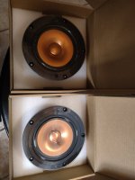
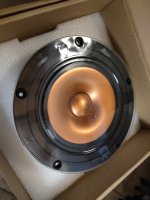
Pair of Beyma 15XA38ND Pro Coaxial Woofers with Compression Tweeters. One Pair Only, like new, used for a few hours of testing. Woofers rated at 350 watts AES, 700w program; tweeters rated at 90 watts AES 180W program. Woofers 8 ohms, tweeters 16 ohms. Powerful lightweight neodymium magnets.

I tested these for use in the Bitches Brew Live Edge Dipoles (link goes to forum thread here on DiyAudio) to cover the range 110Hz to 20KHz. I ended up choosing the B&C 15CXN88's instead, which are 2X as expensive, because the B&Cs have a more consistent directivity pattern than the Beymas from 4K to 7K.

For applications where you want a Coax (ie Tannoy concentric) these drivers are superb and also quite affordable. New units sell for a good bit more.

They can be used as a bass-mid in Open Baffle; with a good bit of EQ they could be used Open Baffle down to about 50Hz in a U-shaped configuration like you see here; in a reflex or transmission line they will go down to 30Hz with 115dB+ output.

WOOFERS 15 inch, 98dB SPL, Fs 38Hz, 6.7 ohm DCR, Qms 6.4, Qes 0.31, Qts 0.30, Vas 238 liters, BL 20.4, Sd 880 cm^2, Xmax 6mm. 4 inch voice coil. See the manufacturer's data sheet for frequency response and impedance curves. Outside diameter 15.28 inches, cutout 13.85 inches.

beyma_15xa38nd_2.jpgbeyma_15xa38nd_1.jpg

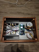
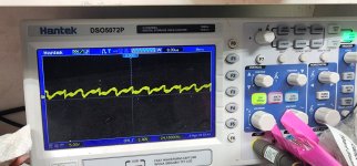
I used these in a bi-ampified active system with MiniDSP digital crossovers. They sound absolutely fantastic. For my final design I opted for a B&C 15CNX88 driver with slightly wider dispersion pattern. The dynamic range is spectacular and the sonic texture is silky-smooth with a good crossover design.
beyma_15xa38nd_8.jpgbeyma_15xa38nd_7.jpgbeyma_15xa38nd_6.jpgbeyma_15xa38nd_5.jpgbeyma_15xa38nd_4.jpgbeyma_15xa38nd_3.jpg
The tweeters have an incisive, detailed and sharply focused timbre. If you want a tight sound radiation pattern with strong directional control, these are ideal. Perfect for creating Tannoy-style or Constant-Directivity Open Baffle (dipole) high-end monitors. Excellent for stage monitors and compact professional sound reinforcement speakers in churches and auditoriums.
beyma-speakers-data-sheet-coaxial-15XA38Nd.jpgbeyma-speakers-data-sheet-coaxial-15XA38Nd_page2.jpg
$749 / pair plus shipping.

I only ship to the lower 48 states in the USA.

Greetings

Hi everyone,

I've been lurking for a bit now and slowly getting tooled up ready for my first build. Started to ask a newb question then realised I haven't introduced myself.

My name's Haden, I'm in England where I work as a Business Services professional in Utilities.

I DJ now and again and occasionally output the odd bit of techno myself.

HiFi-wise, I have a turntable which gets occasional use, an old Technics SL-110 / SME 3009 / Sure V15 III combo, but I'm mostly digital - I run Roon off a fanless Intel NUC and have a RPi configured as an endpoint with an Allo Digione HAT on.

I have a few DACs, nothing too costly, and a nice little Temple Audio Bantam Gold digital amp which I think is an absolute steal when paired with reasonably sensitive speakers.

Speaker-wise, I have just acquired some unidentified passive monitors which sound really nice, if unforgiving. Seem to pair well with a TDA1543 DAC I happen to have. I have just rinsed my local branch of Maplin for a job lot of speaker cable before they close down.

My first build will be Peter Millet's Korg Nutube 6P1 buffer board. After that I have some OEM (Monacor-esque I would say) 10" full range drivers lying around that I'd like to try and do something over the summer with - maybe a boombox.

I've not picked up a soldering iron since school and have almost zero working electronics knowledge but I am not in a rush and would hope that you are patient with me if I ask annoying questions from the steepest part of the learning curve.

Anyway, howdy.
  • Like
Reactions: Mikerodrig27

Help with Bogen CHB100 schematic

I'm going to attempt to gut a Bogen CHB100 and rebuild it from the ground up for a learning experience. I have done recap and board builds and thought this a great amplifier to learn from scratch. I want to remove everything except a volume control and power switch. I have attempted to create a schematic with information I found online but I know my makeshift schematic probably has a couple screw ups. Any advice on what should be changed?
Thanks in advance.

Attachments

  • Bogen-CHB100-HiFi-Conversion-Schematic-1.jpg
    Bogen-CHB100-HiFi-Conversion-Schematic-1.jpg
    194.1 KB · Views: 197

Sony SCD1 "no disc" problem

Sony SCD1 "no disc" problem

Hi, that's my first post here 🙂
I've a SCD1 SACD player (firmware 2.53). Sometimes, whit a lot of discs, the player can't recognize the media and print "no disc" message on display.
The problem occurs with both CDs and SACD with irregular intervals. After the crisis it back to read normally, until the next problem that can occur after a minute or two days later.
Someone knows the reason for this? It's a know SCD's bug?

Someone has had experiences similar to this and knows how to resolve the issue (I would take it into a service center already knowing the cause of the problem!)

I know that there are test discs. Someone knows where to find them and how much it cost?
they are here:

SATD-S1 Optical Pickup Height Adjust disc.
SATD-S2 Reference disc single layer
SATD-S3 Reference disc dual layer
SATD-S4
Reference disc TCD-784

Please hel me!! What can I do?

For Sale 6N23P-EB REFLEKTOR Tubes in original box NOS

I have 12 NOS 6N23P-EV tubes for sale in their original packaging. The minimum purchase is 4 tubes for 100€. The 6N23P-EV packaging original and sealed. The packaging of one of the tubes is no longer firm because of the old glue, so I was able to take pictures of this tube (from 1982). All Tubes coming with the Datasheet inside the tube package.
The price does not include shipping costs. PayPal accepted, registered post plus 5% PayPal fees. With PayPal Freund, the 5% does not apply and can be shipped without tracking, shipping with a tracking number costs around €17.99 within the EU, depending on the package size. Within Germany uninsured with shipment tracking as S-packaging approx. 7€ Shipping within Germany only this week until Thursday. Outside the EU it may vary by country and needs to be checked with DHL.

Attachments

  • 6N23P-EB REFLEKTOR (1).jpg
    6N23P-EB REFLEKTOR (1).jpg
    185 KB · Views: 108
  • 6N23P-EB REFLEKTOR (2).jpg
    6N23P-EB REFLEKTOR (2).jpg
    179 KB · Views: 121
  • 6N23P-EB REFLEKTOR (3).jpg
    6N23P-EB REFLEKTOR (3).jpg
    190.7 KB · Views: 99
  • 6N23P-EB REFLEKTOR (4).jpg
    6N23P-EB REFLEKTOR (4).jpg
    194.4 KB · Views: 101
  • 6N23P-EB REFLEKTOR (5).jpg
    6N23P-EB REFLEKTOR (5).jpg
    166.6 KB · Views: 92
  • 6N23P-EB REFLEKTOR (6).jpg
    6N23P-EB REFLEKTOR (6).jpg
    167.3 KB · Views: 101
  • 6N23P-EB REFLEKTOR (7).jpg
    6N23P-EB REFLEKTOR (7).jpg
    275.3 KB · Views: 89
  • 6N23P-EB REFLEKTOR (8).jpg
    6N23P-EB REFLEKTOR (8).jpg
    286.7 KB · Views: 81
  • 6N23P-EB REFLEKTOR (9).jpg
    6N23P-EB REFLEKTOR (9).jpg
    247.5 KB · Views: 80
  • 6N23P-EB REFLEKTOR (10).jpg
    6N23P-EB REFLEKTOR (10).jpg
    236.7 KB · Views: 83
  • 6N23P-EB REFLEKTOR (11).jpg
    6N23P-EB REFLEKTOR (11).jpg
    284.9 KB · Views: 83
  • 6N23P-EB REFLEKTOR (12).jpg
    6N23P-EB REFLEKTOR (12).jpg
    313.3 KB · Views: 96

Question on near-field low-frequency measurement

Greetings all,

I have rebuild my experimental low frequency enclosure to allow rear driver mounting, and I would like to measure it. However, we are still snowed in, so I was reading on the near-field measurement as proposed by DB Keele Jr in his 1974 paper.

However, my driver ALTEC 515 has a hole, protected by wire mesh, in the middle of the dust-cup, so I was wondering if the method will work. Anybody has an experience?

Kindest regards,

M

For Sale HIRATA TANGO NP-406 LINE OUTPUT TRANSFORMER PERMALLOY CORE

Offer an extremely rare pair of Hirata Tango NP-406N line PP output transformer, core is made with permalloy for the best performance.

It is very good line output transformer, the primary is 40kohm, the max Circuit voltage cannot exceed 1000VDC, the max current in primary is 40mA, secondary impedance is 600 ohm and 150ohm. I bought them in 1997 in Tokyo by Goko Trading a Distributor for Hirata / Tango during that time. The black color was special ordered.

Dimensions: 50 x 56 x 65H mm Weight: 530gr. Both in good condition with light scratches. Worldwide shipping with additional insurance. If you searching for other Hirata Tango Transformers, let me know.

The prices do not include PayPal and shipping costs. Shipping from Germany and with additional insurance only by DHL. PayPal is accepted, the buyer pays the additional 5% PayPal fees. Outside the EU it may vary by country. If you are interested send me a PM.

Offers are welcome!

Attachments

  • Tango NP_406 (1).jpg
    Tango NP_406 (1).jpg
    163.2 KB · Views: 199
  • Tango NP_406 (2).jpg
    Tango NP_406 (2).jpg
    150.8 KB · Views: 118
  • Tango NP_406 (3).jpg
    Tango NP_406 (3).jpg
    194.5 KB · Views: 122
  • Tango NP_406 (4).jpg
    Tango NP_406 (4).jpg
    130.5 KB · Views: 113
  • Tango NP_406 (5).jpg
    Tango NP_406 (5).jpg
    111.6 KB · Views: 137
  • Tango NP_406 (6).jpg
    Tango NP_406 (6).jpg
    277.8 KB · Views: 201
  • Tango NP_406 (7).jpg
    Tango NP_406 (7).jpg
    320.7 KB · Views: 192
  • Tango NP_406 (8).jpg
    Tango NP_406 (8).jpg
    293.6 KB · Views: 212
  • Tango NP_406 (9).jpg
    Tango NP_406 (9).jpg
    644.7 KB · Views: 214

[Theory] Octave pedal with phase shift (inversion)?

Hello!

I have a somewhat theoretical question regarding octave pedals.
Let's assume a nearly perfect pitch shifting algorithm that accurately divides all frequencies by 2 without introducing distortion or other artifacts.
Now, when blending the octave-down signal with the direct/dry signal (externally), would it make a difference whether or not the octave-down signal is inverted or not (phase shift 180°)?
I don't have one yet to test this in practice...

Phantom 48v

I would like to build a microphone preamp with dual power supply and 48v phantom.
I found these two circuits on the net which are a bit different from each other, I mean
to the part circled in red. In #1 the voltages for the 48v are taken from the diode bridge
from an alternating branch and from the positive. In n.2 both are taken from the alternate branches.
Maybe there is a mistake? Which of the two is the correct one?
Thank you
+48v power supply.png


+48v power supply_2.png

For Sale 3 sets of Valve Itch phono PCB

I ordered Valve Itch phono PCBs from JLPCB and the minimum quantity was 5, so here we are, I have 3 sets of PCBs for sale, each set comprising 1 phono preamp (stereo) PCB and the dual heater supply PCB. The PCB were ordered based on jphabc54 in this post. PCBs are 1.6mm black.

I will send to Europe only, as postage to oversea from Switzerland is indecently expensive. I will collect only P+P costs, but I will suggest buyers to add some amount so I can feed back to Salas and jphabc54 over Paypal, to thank them for the work and efforts. Suggest supplement is 20€/set. Contact over PM please.

Attachments

  • jlpcb_itch_phono_preamp_pcb_small.jpg
    jlpcb_itch_phono_preamp_pcb_small.jpg
    195.2 KB · Views: 126

Somtak HF15B Sub inspired by Ripole and Alberich Bass Modules

Hi! This is my first sub project. I am looking into a bass module to put my soon to be mini-karlsonator on top of.
I want to run this idea by some more knowledgeable folks, and this is the place to do that i expect!

I made this little drawing and I humbly ask for any advice that can be spared in pointing out how I might go about calculating or figuring out if this design will work.

I plan to build the cabinet out of 19mm thick plywood.

Well met! Marcus.

Attachments

OK, How about a Music Room in the 20 Million Dollar Range?

I have a thread up on Audio Asylum about a Music Room, the contents of which were valued at about $20 million.

https://www.audioasylum.com/cgi/t.mpl?f=general&m=785566

Getty Music Room jm revs.jpg


Now, there was a SOTA Egglestonworks/Halcro 5.1 music-only Surround Sound system with the capability to play MCH SACDs.

And a 9-foot Steinway grand piano.

But what pushed the value up there was the owner's art and antiques collection, which later was sold off over the course of 10 auctions, totalling over $150 million.

Lots of back-and-forth in that thread!

john

Help! Hypex NCAS500MP

Hello everybody,
by no means, I'm an electronics "guru" quite the reverse.
I will appreciate if someone explains me in the simplest terms how to wire Hypex NCAS500MP H-Bus connector J7.
I will attach the amplifier's pdf.
This amplifier has two power supplies, a standby supply and the main power supply (PS).
Would like to avoid damaging the amplifier with faulty wiring, this is why asking for very much needed help.
The connector looks like this:

1680553857348.png


J7.1 Output VAUX Positive auxiliary supply
J7.2 Output VAUX Negative auxiliary supply
J7.3 Output VOUT,STANDBY Regulated standby supply
J7.4 - GND Ground
J7.5 n.c. SDA (I2C) Not connected
J7.6 n.c. SCL (I2C) Not connected
J7.7 Output DC Error DC Offset detected, power supply disabled.
J7.8 Output Power Good Power supply stable indicator
J7.9 Input PS Enable Power supply enable
J7.10 Reserved Reserved Not connected

Questions I would like to ask for help to answer :
1. To activate the main power supply (PS) and power the amplifier. Is it J7.3 to J7.9 pins must be connected(wired together) ?
2. A standby supply. If I have understood correctly, can be used in external power supply 3.3VDc to 12VDc. This method is favoured by Hypex .
Is it J7.1 and J7.2 pins are used for that ?

Thank you in advance

Attachments

Source to salvage flyback transformer from?

Thinking of building a Jacob's Ladder with/for my kid. Aliex has plenty of the cheap PS's to drive it, but what can I salvage a flyback transformer from? I do have 1 CRT left in the house, an NTSC monitor from the 8bit days, but would rather not take it apart because I think it's worth more to the retro computer crowd. Does any other ubiquitous component (junk) have a flyback transformer in it?

Diy cables, is this wire any good?

Hi all! My dad works for a German company and he had some grounding wire from a leftover job. This stuff is almost 1” wide and it is made of braided copper. It’s super high quality and it is also made by a German company. It is designed to ground large industrial printing presses.

I’m wondering if I can use them for any audio purposes. Maybe making speaker cables? I have to find a way to insulate them. Would these thin and wide braided cables be ok for audio purposes?

Attachments

  • CD1D736D-BA32-417C-A485-B304F87B2CEC.jpeg
    CD1D736D-BA32-417C-A485-B304F87B2CEC.jpeg
    758.2 KB · Views: 145
  • 63F38F40-9108-43A4-A108-75FE7AE5F104.jpeg
    63F38F40-9108-43A4-A108-75FE7AE5F104.jpeg
    694.6 KB · Views: 153

F5 Turbo V3 Magic Smoke

Hi Everyone,

After many years of slow build, I was finally ready to bias my Amp. Due to my limited knowledge of V, I, R and P 🙂 I was expecting failure with PSU itself but it was a smooth ride until now.

DMM
Blue - Connected to P-Channel
Yellow - Connected to N-Channel
Orange - Connected to O/P from FE Board and Ground from FE and PSU to measure DC Offset.

Using Cascode BD139/140
Matched JFET and O/P devices myself.
PSU Voltage : +/- 44V DC
No Diodes on the O/P boards.
In the images, only the lower boards are connected, upper ones I did not connect as I was not confident that I'll be able to bias it without burning anything.

Connected bulb tester and it worked as expected, started bright and then dimming until no light. PSU was/is working fine.

Then started biasing the Amp with bulb tester connected.

  • No light in bulb once capacitors charged.
  • As I started increasing resistance P1(Measured between TP1 and TP2), the voltage on test point on the O/P boards started increasing as did the offset.
  • Increasing resistance P2(Measured between TP3 and TP4) brought offset close to zero.
  • Kept doing this until voltage reached around 0.070 V, took pictures.
  • Kept moving trim pots until I reached nearly 0.100 V on the P-Channel, and 0.093 V on the N-Channel. At this point bulb was lit (not the brightest as in attached image).
-Disconnected the bulb tester and connected regular wire and P-Channel was reading 0.304 V and N-Channel was reading less than 0.200 V and dropping. The N-Channel voltage was dropping whereas the P-Channel was at 0.304.
-Suddenly smoke appeared magically, I couldn't even tell where it came from as there are no signs of any burning (Now I know why they call it Magic smoke).
- Power inlet fuse is also burnt.

Any help would be appreciated. My knowledge on electronics is limited, but if you can tell me which component, pin and what to measure I'll be able to share that information.

Thank you

Attachments

  • DSC_0265.JPG
    DSC_0265.JPG
    276.7 KB · Views: 160
  • DSC_0267.JPG
    DSC_0267.JPG
    252.8 KB · Views: 119
  • DSC_0266.JPG
    DSC_0266.JPG
    246.6 KB · Views: 126
  • DSC_0269 (1).JPG
    DSC_0269 (1).JPG
    361.9 KB · Views: 161
  • DSC_0268.JPG
    DSC_0268.JPG
    360.5 KB · Views: 174
  • DSC_0270.JPG
    DSC_0270.JPG
    327.3 KB · Views: 168

Saba Konstanz Stereo Mod. KN 18 - Audio inputs

Hello everyone,

I'm hoping someone can help me out with a question regarding a vintage amplifier. I'm trying to figure out how to connect an external source to it, but I'm not sure how to do it properly.

The amplifier has two connections, one for a Tape Recorder and one for Turntable, both requiring a 5-pin DIN plug. However, I'm unsure if the Tape Recorder connection is input only, output only, or both. On the panel, I noticed that there are options to select the turntable input and different radio frequencies, but I don't see an option to select the Tape Recorder input.

I have bought a 5-pin DIN connector and plan to experiment with it to see if I can get the amplifier to receive an audio signal through the Tape Recorder connection. If this doesn't work, I'm also considering building an attenuator to feed an attenuated audio signal through the turntable input, following the schematic found on this website: "https://www.epanorama.net/circuits/phono.html". However, I'm not sure if I should follow the design exactly or if I should customize it for this Saba amplifier in particular.

Unfortunately, I haven't been able to find a manual for this amplifier that explains the specifications of these DIN connections. I did find a schematic on this website "http://radio1.3dn.ru/manual/saba-konstanz-18-stereo.pdf", but I don't have much experience with electronics aside from basic soldering and using a multimeter.

I'm simply hoping to be able to connect an analog audio signal to this wonderful vintage amplifier. Any advice or assistance you can provide would be greatly appreciated.

Thank you in advance for your help and suggestions.

Here are some pictures:

DIN-5 connections

DIN-5.jpg


Panel
I don't know if the 'Stereo' switch is a push button or if it's broken, because it doesn't stay down when I press it.
*This picture is from another unit I found online.

Panel.jpg


Wider pictures from the back

lautsprecher.jpg
Saba Konstanz Stereo KN18.jpg

SMPS + Bank Caps

Coming here to get some help with the cap bank reservoir.

I've tried to add two 70k uF 16v cap nearest the high load device but the problem is that the SMPS goes somehow in protection from the inrush current required from the caps.
It simply won't startup, maybe a NTC Thermistor?
Any suggestion? The load would be 350w-400w +-

This is the cap : https://www.mouser.com/ProductDetail/80-ALS30A683DF016

Mounting TO220 heatsinks

Finished building a SSMH hpa and just ordered a case. The heatsinks for the mosfets have just two friction fit pins on the bottom for soldering to a board I assume. These will be mounted on the outside of the aluminum case, vertically.

How do most people mount them? Do I need to remove pins, then tap threads into the channels and use screws? Something obvious im missing? I'm completely new to this and built without any detailed instructions other than a pcb, BOM and schematic. Trying to learn this simple stuff as I go.

These are the heatsinks I have.
Screenshot_20230331-111622_Chrome.jpg

Where to place regulator in two box phono preamp?

Hi! I'm building a KA-Electronic Flat MC Preamp, and plan to place the amp in one box, and the transformer and rectifier board in another box. I also have a DIYINHK regulator board, but I'm not sure which box would be the best to place the regulator in? The regulator is linear. In the below picture the regulator is placed in the psu-box, but noise wise maybe it is better to move it to the amp-box?

Attachments

  • IMG_8084.jpeg
    IMG_8084.jpeg
    530.4 KB · Views: 135

TASAV 4 class AB Mosfets exicon

Hello ,
I have to sell 3chanel TASA v4 classAB power amp all for $150.
one Channel is good working and another two is control board problem need to fix .
mosfect power board is no problem total Mosfets exicon 30 pcs is still new condition . Come with 6mm aluminium plate .

best regard

Attachments

  • E932CAC3-93F9-4C31-B7FF-5768E76288A1.jpeg
    E932CAC3-93F9-4C31-B7FF-5768E76288A1.jpeg
    609.1 KB · Views: 92
  • 283F99F8-948F-4696-948E-86FA96E30B84.jpeg
    283F99F8-948F-4696-948E-86FA96E30B84.jpeg
    565.3 KB · Views: 102
  • E2ED9949-C892-4AE3-B706-3207981FCB4F.jpeg
    E2ED9949-C892-4AE3-B706-3207981FCB4F.jpeg
    471.9 KB · Views: 90

WaFR: Mark Audio LS120/4 (2xCNH-40/CHR-120)

Realistically this is a multi-way speaker, but the full range afficianados live here, so... here we find ourselves 🙂 Has Wideband assisted Full Range been coined before?

Having built 7MS FH Mk3s, a CHR-120 big-vented box, a P11 boombox, a very capable ~19L 2-way, AND being a huge fan of the 'old school' multi-way large volume format, the LS120/4 lies centrally in my Venn diagram of speaker design love:

Screenshot 2023-04-02 at 6.42.28 pm.png


From: https://www.markaudio.com/wp-content/uploads/2022/10/MA-LS120-4-1.png

Would I be the first to build these? Dan at Darcher Audio here in Aus has both drivers in stock so I'm itching to tackle this one; any wisdom, tips or greivances about where this has been posted would be appreciated.

Of most interest is whether the XO was based on measurements or simulation - the former I am keen to do if not.

Also of interest: Scott, Dave, who penned this? The drawing is not attibuted.

Schulmerich 805 Amplifier Set Western Electric AT&T patents

Seeking anyone interested in a pair of high powered Schulmerich built 805 tube amplifiers using a design licensed by Western Electric / AT&T. Included are two amplifier chassis using 805 tubes, two separate power supply chassis using 3B25 tubes, as well as a two channel driver amplifier that provides the correct input signal for the power amplifiers.

The transformers are substantial and added up they are estimated to weigh 400-500 lb including the cabinet but not the extra output chassis.

These are contained in a single rack mount cabinet with a meter on the front. Also included is a spare amplifier chassis which has the pair tubes present as well. Each amp is rated at 300W RMS - they were used to drive a large number of horn speakers on an electromechanical carillon bell system which could be heard for miles when the volume was turned all the way up.

All units were re-capped using film capacitors and electrolytics that are commonly used to restore vintage tube amplifiers and antique radios.

These are listed on eBay where you can see more photos and details here.

Willing to discuss further with anyone that may be interested - feel free to send a PM here. Pickup near Milwaukee, WI - though I am open to negotiation on the pricing and can helping with shipping arrangements, either by uShip or Freight. I've bought and sold large items (including church organs!) this way, so have some experience getting items safely to their destination.

How to wash your PCBs in your kitchen safely..

I've found affordable PCB cleaning water-based liquid, literally no smell that's critical to me cause I work at home. 10 parts of 50-70C hot water for 1 part of XCY-1007($3 for 500mL), 3-5mins in ultrasound, next wash by water, and dry with a hairdryer. A perfect result virtually for free! However, XCY-1007 is available in China only.
For my test, I intentionally added extra flux(something like modded rosin from a solder wire core), also, I did burn it with overheated iron to carbonize the flux. As you can see such a complication isn't fully removed by XCY-1007. It seems, need to increase the ultrasound processing time or the concentration of XCY-1007.

XCY-1007.jpg
  • Like
Reactions: availlyrics

Trace arithmetic to extract woofer/tweeter z-axis offset?

I have a set of DIY two-ways consisting of AE TD15M & BMS 4550 on QSC waveguides. I've been using a miniDSP 2x4 for a long time, but want to design a passive crossover for gear simplification.

I only have a USB mic, single-channel measurement setup. The obvious drawback is timing measurement. I could likely work with a few assumptions and get close enough with a VituixCAD design, but would like to do all I can to get this right. I also cannot really physically change the driver mounting at this point.

With the 6 following measurements available, all 200Hz-2kHz, taken at the y-axis mid-point:

woofer, normal & inverted;
tweeter, normal & inverted;
parallel woofer & tweeter, in phase & tweeter inverted;

Could I use trace arithmetic in REW to extract the correct z-offset? The IR of both driver together is mostly that of the tweeter and I cannot really make out the woofer's impulse.

I thought I'd set tweeter IR peak at t=0 for the together-in-phase trace, same for the tweeter-normal trace, then subtract the later from the former, hopefully leaving the woofer's IR peak 'legible', at its now correct offset. I suppose the same could be achieved by adding the inverted trace instead.

Does this sound sane? Is there a better way with these of different measurements?

Oh, I posted this in Multi-Way thinking it might get more views than in Software, but if more appropriate, I don't mind if the post is moved there.

4x6" bass cabinet

Hi, I am planning to do a new cabinet for my bass guitar.

I am thinking in 2 options.
First one is use 4 Beyma 10CMV2 drivers the volumen of the cabinet should be 200 liters to go down to 47Hz
Second one is use 4 Beyma 6MNFW drivers the volumen of the cabinet is just 50 liters to go down to 38Hz

I will use Beyma because is what I can get here.

The 4x10" will go up to 129dB, the 4x6" up to 120dB.

Normally is for small/medium size stages.

4x6" is smaller but more expensive the 4x10" is bigger but cheaper.

4x6" 1000€ 50 liters.
4x10" 200€ 200 liters.

Im not an expert so any advice will be appreciated.
I did the simulation with WinIsd software.

Thanks for you help.

For Sale LM4780 Basic diy stereo amplifier kitt.

LM4780TA Diy audio amplifier kit for sale 29€ more shipment.
LM4780TA with PCB high fidelity class AB 2x60watt amplifier
Tracked shipment, shipment to US on request
Skematics sended together with articles
Payment by paypal

1668261967152.jpg

Attachments

  • 1668261157716.jpg
    1668261157716.jpg
    404.3 KB · Views: 102
  • 1668261241302.jpg
    1668261241302.jpg
    469 KB · Views: 84
  • 1668261157709.jpg
    1668261157709.jpg
    375.8 KB · Views: 96
  • Like
Reactions: aditya
Projects by fanatics, for fanatics
Get answers and advice for everyone wanting to learn the art of audio.
Join the Community
507,648
Members
7,882,654
Messages

Filter

Forum Statistics

Threads
405,961
Messages
7,882,654
Members
507,648
Latest member
nguyenbatrinh