Current production non-polar electrolytic capacitors for speaker networks?

I’m using Nichicon UDB series at the moment for crossover networks. They have excellent ripple current capability compared to other types of electrolytic.

EF80C890-CC53-4BC3-9667-96EB4CC7F83D.jpeg


Luckily, this is not one of the series being dropped by Nichicon in their recent end of life announcement.

Are there any other current production capacitors specifically for speaker networks? I’m not sure what I would use if they stopped making this.

Aleph2 60V PSU and Heatsink

Hi Everyone,

I have assembled PCB for Aleph2, just waiting to mount them and have some questions.

1. Aleph PSU is 57V, after going through similar threads what I have understood is that no modification is required to circuit for 57V rails. If someone can confirm, that would be confidence boosting.

2. Can I mount 12 O/P Devices of Aleph2 on one heatsink 600 X 300 X 84
Therm. Resistance (°C/W) @ Length 200mm - 0.08
Ambient Temp : 35 C

3. What if I want to decrease the bias a bit as I need 100W per channel. Will lowering bias have any impact on sound quality.

4. To decrease bias i need to use a pot in place of R19 in original schematic ?

5. Do I need to match MOSFET for Aleph2?

Sakuma's bleeder tubes and series connected transfomers

Hi!

I just browsed Sakumas website and found some of his latest works. Sakuma is known for his unconventional circuits. He added some new twists to his latest builds.

There are 'bleeder tubes' added to provide some load to the power supply. Probably for stabilisation. But why use tubes instead of a plain resistor? He even uses expensive DHTs for this purpose like a WE300B here:

12AT7 / 841 SE phono preamplifier

There is even a transformer added as a load to the tube, with the secondary just grounded on both ends.

Here he uses a 50:

5691 / WE-102D SE phono preamplifier

This time even with an input transformer.

There is probably some reasoning behind it, did anybody read the MJ magazines in which these circuits got published? Was there an explanation why this was done?

Also quite interesting the use of several transformers connected in series as a load to enable transformer coupling of high rp tube like the 841:

841 SE Tone control and buffer amplifier

Best regards

Thomas

Luxman A373 - D375 - T353 Integr. Amp - CD - FM-Tuner

For this Luxman hifi system I need a new MCU for each component.
The type No are follow:

1) Integrated Amplifier "A-373": TMP47C860N-G091
(TMP-47C860N-G091) Toshiba

2) Compact disc player "D-375": HD404729877S-35096WO3 (HD-404729877S-35096WO3) Hitachi

3) Stereo FM Tuner "T-353": TMP47C862AN-P527
(TMP47C862AN-P527) Toshiba

All parts are no longer available. Thus I am looking for other possibilities.

First possibility is to find out other models and brands with the same MCU's and same firmware.
Perhaps one of you know any models (most important is the amplifier).
Second possibility is to buy universal MCU's without firmware for own programming and additional the genuine Luxman firmware.
Who know appropriate delivery sources and suppliers for this?

BTW - the last is a general problem by much more other old audio components and therefore I think, there are some special company for offer this.

Thank you very much for your advices.

Attachments

  • luxman A373 front.jpg
    luxman A373 front.jpg
    70.8 KB · Views: 512
  • Luxman D375 front.jpeg
    Luxman D375 front.jpeg
    41.3 KB · Views: 515
  • Luxman T353 front.jpeg.jpg
    Luxman T353 front.jpeg.jpg
    42 KB · Views: 471

TPA3118 Noise connected to RPI

Hello i need some help please.

I have the next
  • RPI Zero W
  • MAX98357 I2C
  • TPA3118 Board
  • 12v 5a power suply
  • 5v 2a power suply
  • 40w 8Ohms speaker
If i connect TPA in mobile 3.5 jack the som is clear without any noise and good sound quality.

But if connect TPA in RPI got a noise whether the audio is paused or playing (it stays in the backgroud)

My connection is:

220v -> 12v -> AMP -> Speaker
RPI -> MAX98357 -> AMP In

I try
  • RPI connect USB from PC (Noise)
  • RPI Connect to External Power (Try Apple, Samsung and Huawei power suply) (Noise)
  • RPI Connect to Step Down (No audio only noise)
  • RPI Connect to 5v HI-LINK 2a buk (Noise)
If i connect MAX98357 directly to the column (RPI -> MAX -> Speaker) I don't get any noise but the sound is very low as the output is only 3w

Thanks for any help / hints

Cheap toroidal transformer for ESL panel

Hi,

I'm interested in creating a new mid / tweeter esl panel together with a dynamic woofer. The advantages over a full range esl would be:

  • cheaper transformers
  • higher efficiency, lower polarizing voltage required, less aging of materials?
  • no damping screen required to tame fundamental "one note bass" resonance, which leads to better, more transparent, less muffed sound, in my personal experience (biggest reason)
  • lower step up ratio required of audio transformer resulting in extended HF range compared to full range audio transfomer

I would like to chose my cross-over frequency somewhere between 150 and 250 Hz. The esl panel will be electrically segmented.

So I've read some topics here about cheap toroidal power transformers. Unfortunately I lack some technical background, so I have some questions before I order them:

  • which primary voltage should I choose: does it make a difference and if so, which one is preferable to the other? For instance, should I pick 2x6V, 2x7V, 2x8V, 2x9V, 2x12V, 2x15V or 18V? I would think a lower voltage would result in a higher step-up ratio and lower saturation frequency limit?
  • If I'm correct, 1x230V is preferrable to 2x115V as these have a high capacitance and limit the bandwidth*
  • Would 15VA power rating suffice? If I'm correct, this would suffice for electrically segmented panels, not for unsegmented big panels*

* source: https://www.diyaudio.com/community/...wer-toroidal-transformer.399698/#post-7365361

I managed to find two transformers and I'm wondering if they would be a candidate?

230V ac, 2 x 9V ac, 50VA 2 Output
https://nl.rs-online.com/web/p/toroidal-transformers/2237888?gb=b

230V ac, 2 x 6V ac, 50VA 2 Output
https://nl.rs-online.com/web/p/toroidal-transformers/6718959

Calculating sensitivity of various multiple driver arrangements

I'm working on a project with multiple smaller drivers in various baffle arrangements and wanted to know if there was a reliable way to sim or calculate total system voltage sensitivity and in which areas of FR any gain would be seen.

As an example, if I were to use 6 x Peerless 830870 bass-mids (3 paralleled groups of 2 series connected drivers in each group) in a tight circular grouping around a centrally positioned tweeter. Driver specs attached below >>>

- In which FR range would I be seeing sensitivity gains?

- At which frequency will the drivers acoustically uncouple from each other?

I understand the CTC spacing of all the drivers matters most here, but also the geometry of how they're arranged ie. if we're dealing with an oval arrangement, not just a simple circle or line array configuration.

- Which software is best at figuring this out? I understand Basta does this to some extent, but it won't run on my PC for some odd conflict reason.

Attachments

  • 20230831_110634.jpg
    20230831_110634.jpg
    230 KB · Views: 104

Standing Waves in Mid-Range Pod?

I've built cylindrical pods (completely sealed enclosures) for 2.5-inch midrange drivers that will mount on the dash. They'll be playing ~700-4000hz.

Would it be worthwhile to treat the inside of the enclosure (e.g., put foam on back wall or add Polyfil)? Do you think it would reduce the possibility of standing waves in the enclosure or affect the sound in any way?

Thanks in advance for your input!

I heard a cabinet talk.

I own a pair of ADS L1590/2 and I’m delighted with them, although they have some fault designs.

As you can read the review on this link: https://www.audioasylum.com/reviews/Speakers/ADS/L1590-2/speakers/32/322122.html. I couldn’t agree more with the reviewer that we found “the cabinets exhibited a lot of talk”. There were a lot of “Ummm” sound on the male voice and some blur on the instrument.

Anyway, I had built a diy pair that copied the L1590/2s dimension since I was fascinated with their appearances. The cabinet of this diy pair had identical external dimension to preserve the L1590/2s look. But, the thickness of the MDF was only 16 mm. while the original has 19 mm. (same MDF). And all bracings inside the cabinets were the same pattern as the original.

BUT, the result was different. There were no cabinet talks on my diy pair at all!

Could anyone please explain why I didn’t find a cabinet talk on my replica despite the fact that they had the same dimensions, and also had thinner cabinet wall?

About the woofers in the replica, they were car subwoofers where ADS fans called them the 4-Ohm version of those in the L1590/2. Low-pass crossover is crossed at about 700 Hz, whereas the L1590/2s is about 350 Hz.

Attachments

  • EBD68D4D-505C-40F3-9E1F-F9E4866E563C.jpeg
    EBD68D4D-505C-40F3-9E1F-F9E4866E563C.jpeg
    397.2 KB · Views: 94
  • CBFB6839-3BA9-4916-9CF5-7FAA0FAC4D98.jpeg
    CBFB6839-3BA9-4916-9CF5-7FAA0FAC4D98.jpeg
    366.9 KB · Views: 89

Fixed bias design

Hello 🙂

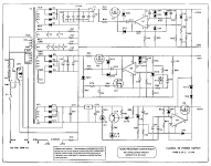
I am designing a fixed bias circuit.
Although the bias circuit is not complicated, several doubts arose during the design process...
I have no experience in building amplifiers, so any advices, tips, suggestions or approve will be appreciated 🙂
Maybe I forgot something or made a design mistake?
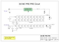
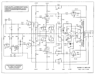
Design
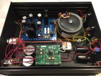
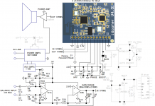
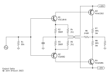
The bias circuit is designed for a parallel single ended power stage with two KT-150 valves per channel.
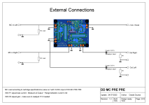
-bias will be powered by a separate transformer (it will be custom made to order)
-each channel will have its own transformer/PSU circuit (dual-mono design)
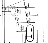
Safety resistor
Many schematics found on the net lack a safety resistor protecting the valve from burning if the pot's wiper goes open.
In the circuit shown, there is a safety resistor 200 kOhm.

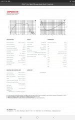
KT-150 datasheet resistance
KT-150 maximum grid circuit resistance for fixed bias is only 51 kOhm.
I assume that the value of 51 kOhm "Maximum grid 1 Circuit Resistance / fixed bias" given in the datasheet is the grid to cathode/ground resistance.
(There may also be the grid to bias power supply resistance (cap)...or... grid to cathode/ground resistance through the psu ground???)
There will be two valves per channel (paraller single ended), so the driver will be loaded with a parallel combination of its own anode load (choke) and two resistances in the power stage.
(A grid choke could increase the impedance, but so far the design does not include it)
In the diagram shown, the grid-to-cathode (ground) resistance is approximately 51-53kOhm, depending on the bias setting.

Adjustment range
The bias adjustment range is useful for experimentation: -40 to -60 volts
(Need about -50V for quiescent point 129mA/480V anode voltage, dissipation <90%)

Resistance change
I tried to ensure that the change in the bias voltage did not cause a large change in the resistance value of the bias circuit.
In the diagram shown, a change in the bias voltage in the range of -40 to -60 volts causes a small change in the grid-to-cathode/ground resistance: 51-53kOhm.
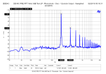
Voltage filtering
The bias voltage should be properly filtered, because a small change in the bias voltage causes a large change in the current flowing through the valve.
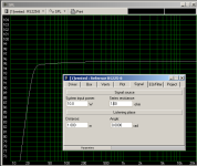
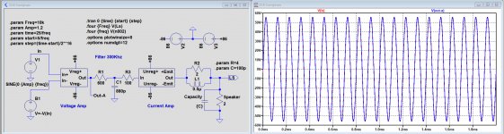
The PSUD simulation shows fluctuations around 70uV peak to peak (when the transformer has 100ohm resistance and the reservoir cap is 100uF)
Is this filtering value enough? 🙂


Transformer
I am wondering what VA power of the transformer to choose and what its resistance will be.

Probably the power should be several VA and the resistance will be several hundred ohms (smaller VA -> greater resistance).
The VA formula is: Vpri x Ipri or Vsec x Isec. Plus, a little oversize...
Resistance formula: Rs(equiv) = Rsec + Rpri/(Vpri/Vsec)^2
The required transformer voltage is related to the resistance (...and the reservoir cap), I don't know the formula to calculate this dependence.
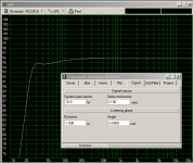
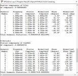
The PSUD simulation shows the following RMS AC no-load voltages (rounded values), depending on the transformer resistance:

1Ω - 74V (theoretical resistance value, for powerful transformers)
50Ω - 77V
100Ω - 80V
200Ω - 85V
300Ω - 89V
400Ω - 93V
500Ω - 97V
600Ω - 100V
700Ω - 104V
800Ω - 107V
900Ω - 110V
1000Ω - 113V
2000Ω - 141V

The bias circuit draws a small amount of current, about 20.5 mA (although for the bias circuit, this can be quite a lot).
When the power supply has 100ohms of resistance (probably the value will be higher...) and the 100uF reservoir capacitor (crucial for good voltage filtering but resulting in higher current "spikes"), the PSUD shows:
-peaks of current drawn from the transformer -115mA / + 115mA, during normal operation
-During startup, the inrush current fluctuates between +860mA / -560mA.

So, 3VA / 4VA should be enough? 🙂
Bias2.png
psud 100ohm 80V.jpg
psud 500ohm 97V.jpg


Resistance to psu cap
The signal may be going back to bias power supply cap
, isn't that a rather desirable behavior?
A large 47kOhm resistor should provide high signal resistance to the bias power supply.

Potentiometer
The pot is Bourns 3549S-1AC-202B, withstands 2W.

Special resistors
Will the use of non-magnetic or non-inductive resistors bring any benefits?

SiC Schottky Diodes
Would using SiC Schottky Diodes (Woolfspeed CSD01060E or CSD01060A) instead of 1N4007 be a good idea?

My first go at designing a cross over

Everyone knows that idle hands are the playground for the devil, so, I went and did a thing. I am a complete and utter noob to any type of home audio. I have time on my hands (aka boredom) from time to time and have always wanted to do something a little different. In my early 20's, I was head over heels in car audio. Nothing hi-fi, just wanted to see if I could literally shake apart my vehicle and annoy other motorists. Well, some years have passed and the audio bug has reared its ugly head again. Although, this time, I am having a hankering for something more civilized and, from what I'm learning, in a whole other league all it's own. Home audio leaning towards hi-fi. I'm not striving for audiophile levels, getting too far off in the weeds like that would probably lead me to sleepless nights with ideas popping out of no where and it would bug me relentlessly till I either made a note of it, satisfied with that, or testing it on some simulator or program.

So, here we go. This is a list of the components I've chosen for the cabinets.

(1) Dayton Audio DC28F-8 1-1/8" Silk Dome Tweeter​

(2) Dayton Audio DC130B-4 5-1/4" Classic Woofer Speaker​

(2) Dayton Audio SD270A-88 10" DVC Subwoofer​

This list is just for a reference for the cross-over mumbo jumbo that has come together thus far. I know that there are better components out there, these are my chosen ones for this project.

Now for the brain blender. I have used the Xsim program to clank out a crossover for this Frankenstein. I am attaching pics of what I have brewed up thus far and for all to critique and tell me what I am doing wrong (aka suggestions, ideas, or I'm on the right path). Again, I'm not going for audiophile, this is a hobby not an addiction for me.

Thanks in advance for all the kinds words I know are coming my way.
crossoverschematic.jpg

crossoverschematic.jpg
totalfrequencyresponse.jpg
driverfrequencyresponse.jpg

Would you expect mains harmonics out of an LLC resonant half-bridge converter?

I have one of these LLC resonant half-bridge converter tube amp supplies. It provides
  • HT: 200V to 520V 300W maximum.
  • DC1 and DC2: 2.5V-6.5V adjustable 15W peak 7.5A.
  • DC3: fixed output 2.5V-15V, customizable, maximum 10W (not sure how it can be both fixed and customisable!)
  • DC4: -10V to -120V 50mA maximum
Yes, it's cheap for a full stereo tube amp power supply. This is what the amp output looks like:

Amp output SMPS only 190mV RMS into 8Ω.png


Here's level vs frequency for the HT supply

SMPS level vs frequency.png


The bias supply looks worse.

I was expecting to need voltage regulators to clean up switching noise at ~100kHz+, but not mains harmonics or the humps at 1.5kHz, 2.8kHz 4kHz etc (no idea what's causing them).

The mains is rectified and filtered with 3 470uF capacitors before the resulting DC plus ripple is switched in the vicinity of 100kHz. 100kHz HT is rectified and filtered with a capacitor/inductor filter. The bias supply is half-wave rectified, filtered and regulated with a simple single transistor regulator.

The schematic for the converter is standard. The control daughter-board is coated so it's not possible to identify the controller and supporting components. Output level would be regulated with a feedback loop to the LLC resonant controller. No idea what it's time constant/s are. Perhaps the rectified mains ripple would go straight through.

Switch-mode power supplies can be noisy but LLC resonant converters with zero voltage switching of the MOSFET switches and zero current switching of the rectifiers shouldn't be. With good design and PCB layout performance should be acceptable. They're widely used in flat screen TVs, EVs, solar and even commercial HiFi.

The voltage regulators on the HT and bias do a good job but... would you expect mains harmonics out of such a converter?

Replacing capacitors, but can't find the correct values.

I'm working on the family Philco 51-1732 and I would like to replace the electrolytic capacitors, but it's mutliple capacitors in one can and I haven't been able to find the correct replacements. The needed values according to the manual are 2 40uf, one rated at 350V and one 400v, and a 60uf at 400v. I can find 33uf, 47uf, and 100. I could potential get my hands on a 80uf 450v. I've attached the section of the schematic with the capacitors in case it would make more sense to do something different. I have the full schematic as well if necessary. As a hobby I do a fair amount of work with electronics but mostly just parts swapping, so thanks for any help!

Attachments

  • philcocaps.png
    philcocaps.png
    99 KB · Views: 196

Alpair 7P & Alpair 12PW combination.

Hello Lads (Ladies also....I guess there should be some in audio)

Now comes the real fun.........getting the best system combination by bringing together the Alpair 7P with the Alpair 12PW. There are some very interesting features to consider:

Where to cross.
The responses of both drivers give a great deal of choice. The 12PW will easily allow those system designers who prefer to cross higher, outside the telephonic band high point of 4kHz, you should be able to achieve your desire using the 7P/12PW combination. Equally for those who prefer further down, around 400Hz for example, your needs can also be accommodated by combining these 2 drivers.

Remember that you're working with 2 very similar drivers. Both have inclined shallow cone profiles that emit similar dispersion patterns. The Alpair 7P effectively becomes a super-sized tweeter while the 12PW is a wide bander capable of emitting to +10kHz. Don't assume that many of the "standard" cross-over methodologies are a "default" good fit. Experiment by starting off with simpler designs. Don't go nuts with complex cross-over designs with bucket loads of components, as both drivers power-trains are ultra sensitive. They will pick up increased signal deviation caused by the more complex cross-overs.

There's allot of cross-over designs and a ton of theory that can lead to a great of heated debate. Remember to be "reasonable" when debating ideas. Those who post with a "know-all" attitude risk be delated. Experienced members familiar with Markaudio drivers could be a good source of advice and ideas - thanks in advance guys.

Box designs.
Regarding box layouts, remember to isolate the Alpair 7P from the 12PW. Otherwise you risk cone blow-out on the 7P. For those crossing higher, allow 4 to 5 litres of internal compartment space for the 7P, mostly to avoid internal reflection. Those crossing lower <1kHz, allow 5 to 7 litres, assuming your not going under 400Hz.

Driver positioning......try to keep the drivers as close together as possible. The less distance between the drivers, the better.

I've got to rest now guys....

Enjoy
Mark.

Attachments

  • Alp12PW-Alp7P-1b.jpg
    Alp12PW-Alp7P-1b.jpg
    84.7 KB · Views: 3,933

Repairing my NAD C 355BEE

My NAD C 355BEE broke. I believe I connected a speaker cable carelessly and it short-circuited one of the terminals to the case next to the terminal. Seems like there was no protection circuitry for an accident like this. My Leach Amps have survived a similar incident with only a blown fuse. This also blew both 41 V AC fuses immediately, but still not fast enough it seems.

One 2SA2121 is a short from every pin to every other pin. Also the corresponding 2SC5171 that used to drive it is shorted.

I removed all four power transistors from the heat sink and plan to replace all four power and all four drive stage transistors.

There are no 2SA2121 or 2SC5949 available anymore. Lenbrook recommended that I contact my local representative. They in turn recommended that I use 2SA1943 and 2SC5200. I'd myself prefer 2SA1987 and 2SC5359 because these are 180 W, instead of the 150 W of the recommended pair. The originals were 220 W (Toshiba's information here, page 7).

My first question is, should I get these from Kessler, or a local parts shop that is slightly more expensive (Partco), or from some other place in Europe? From Kessler I would buy more parts "just in case", but from Partco I'd buy only what I need and then go back for more.

My second question is, should I just use standard silicon pads that are 0.4 K/W or would there be a problem with mica and thermal paste on both sides? I have mica + thermal paste in my Leach Amps, but in the case of the NAD I wonder if the mica insulators will stay in place. There are no screws through them. Only a clamp pressing on the transistors. Is this thing even running anywhere close to its limits?

Kessler did not respond to my question about the specs of their TO3P silicon insulator, but their feedback form also gave me some fatal error after eating my message.

My third question is, should I expect to find even more damaged parts than one driver and one power transistor? I plan to power the amp up using a bench power supply with a current limiter and compare the channels using a multimeter and possibly a scope, feeding a test signal through the main in connectors. I might even simulate the whole power amplifier in MicroCap if that doesn't prove to be too difficult.

For Sale Dave Slagle line out/interstage transformers, 80% Ni, silver secondary

Hi!
This post is to test if there is interest in these transformers, or if they have to go on the shelf. Currently they are still in circuit. If there is interest I will take them out to take pictures. I can also measure them with e.g. a QA403.
1 pair of interstage/line out transformers. 80% nickel cores. 4:1 winding ratio. Gapped for 35mA. Wound to load a triode strapped E55L (Rp 600R). Primary winding copper, secondary silver.
Transformers are located in Germany, I'll ship anywhere.

Please get in touch if there is serious interest, I'll take pictures and post more data.

Metronome audio leaking into guitar preamp, and tl022 mixer not working

I built this metronome, with an added volume knob at the end:
http://www.555-timer-circuits.com/metronome.html and I built this guitar preamp: https://electronicscheme.net/guitar-pre-amp-with-jfet-2n5457/guitar-preamp-design/ and it works fine on its own, but when I connect the metronome to the same 9v battery, the metronome leaks into the preamp's output. Is this because of the capacitor between power rails in the preamp? It's not in the preamp circuit. If that's the problem, how do I separate the capacitor from the metronome's power rails? Also, I built the mixer circuit#2 on this page to mix the two signals: http://www.all-electric.com/schematic/simp_mix.htm using a TL022, but I'm not getting a signal out of either opamp.

Listening rooms for a composer's 2024 tour

Dear Community,

I am an ambient/drone music composer planning a tour for spring 2024. Typically I pursue traditional venues, but I had a whimsical idea ... to play DIY/hi-fi enthusiasts listening rooms.

Why not? As I — & my collaborators — often play for more intimate audiences anyway, & don't require massive systems, what's the need to perform in large venues with pa systems that are generic, one-size-fits-all & far from optimized? Moreover, I would love to hear my music on a lot of the different systems that are featured here, & give them an objective testing 😉 I bet many of you would love to show off your ingenious creations, as well as see how they perform in a different context.

In general, I think this could be a fun social experiment, but also offer some real possibilities for research & connecting dots.
Would be curious to hear people's thoughts. If you're interested, pm me.

Failing resistors on Gemini XGA5000

Hi everyone, new here 🙋🏽‍♂️.
Im trying to fix the amp but two 1k resistors that leads from the mains to the input pcb keeps on failing. I looked for short, and there is but after a while it disappears (bad cap maybe 🤷🏽‍♂️). It is fairly simple design but unfortunately I couldn't find schematic. Can someone help me figure it out? Thanks
IMG_20230902_210652.jpg

Attachments

  • IMG_20230831_170655.jpg
    IMG_20230831_170655.jpg
    224.5 KB · Views: 112

Lets look inside some audio resistors

Hi, I have thinking of this for a time. Lest see what is inside the audio resistors we use.
So I pick some from my part box.

From left to right: Mundorf-Metal Oxide Film, Mundorf-Wirewound, Mundorf- Bibilar Wire, Duelund-Graphite, Lefson-Silver/Carbon, PathAudio-Thick Film.

Attachments

  • IMG_0486.jpg
    IMG_0486.jpg
    692.5 KB · Views: 439
  • IMG_0490.jpg
    IMG_0490.jpg
    570.9 KB · Views: 409
  • IMG_0491.jpg
    IMG_0491.jpg
    665.4 KB · Views: 429
  • IMG_0493.jpg
    IMG_0493.jpg
    431.3 KB · Views: 407

Stamm upgrade of Lowther

I tend to get phone calls from people aware that I know my way around repairing Lowther units.

Last summer I had the pleasure to get my hands on a pair of Stamms for repair and they were fascinating. I haven't been impressed with other Lowther clones, notably AER whose snake-oil claim that they reproduce up to 80kHz doesn't impress me. But Stamm knew what he was doing.

The owner of the Stamms is a record producer and he's succumbed to a pair of Tannoy 15 inch units, simply as they're standard kit, and therefore selling his Loth-X fitted with Stamm.

These units I fitted with spider and surround that will not rot and if those units don't last 100 years I'll be surprised. On ebay at the moment - https://www.ebay.com/i/193824270639

Best wishes

David P

WTB: manual(s) for TEKTRON TK Two 2A3/50S-i early (pre-2010? - model)

Recent acquisition without owner’s manual. Bought from second owner, local organizer for high-end audio gear shows of some renown.
Yes, I contacted the factory. They say it’s theirs. NO serial number or signature or any other ID inside/on the amp.

IMG_2311.jpeg


I contacted US/Canada distributor and was emailed a schematic dated 2015. (Thanks, Don)
Amp is much older than that with wiring, components, substantially different in earlier model I have. Trying my hand at circuit tracing/schematic creation but…

I’m GUESSING, based on a 6moons review of this amp March 2006 that it’s at LEAST that old as it looks JUST like the one in the review.

http://6moons.com/audioreviews/tektron/tektron.html

It has machined aluminum (not molded bakelite/resin) knobs, US -made Audience/Auricaps (first gen, not XO) and “Tech-caps” inside if that’s a clue to age and uses a 5Z3 rectifier.

How does it sound?

Except for a slight 120 Hz hum (should have new 5Z3 and power caps in a few days), just AMAZING!
And this is while running 21 year old basic Sophia 300b tubes (SN 292 and 309 with original data cards) I’m told are original to the amp, 1944 model 6F8G matched drivers (it came with SOVTEK 6NHC tubes - 6SN7 equiv.) into Klipsch Heresy IV’s and j just ordered a pair of EML 300b I look forward to breaking in.

I like having original manuals/data sheets for amps, preamps, other gear.

Hoping someone has this information and could photocopy, make PDF files or just send clear hi-res photos to me via email.

For actual manual? How much?

Thanks.

Norm

WinISD Pro query

I haven't built anything yet so still a paper exercise. Couple of things I have noticed. Max power and max spl graphs never show anything. Is this normal? Then ...........

At times cone excursion and the 2 transfer functions in the same block of options (magnitude and phase) do the same thing. I can only get them to function again by reloading the project.

I'm trying to come up with a woofer to go with 2 existing speakers so I looked at adding series resistance in case the woofer spl is too high. It has this effect

I appreciate appreciate adding R alter the Q's but the change 1ohm makes to spl may not be enough. Increase that and the graphs mentioned go blank at some point. The other factor is that adding R changes cone excursion as well - in a beneficial way. Those 2 shots were taken with those particular graph's showing nothing. So all of the others remain ok.

I'm a bit bemused as to why this happens and if there is a fix.

Attachments

  • WinISD0_1ohm.png
    WinISD0_1ohm.png
    6.7 KB · Views: 152
  • WinISD1ohm.png
    WinISD1ohm.png
    7 KB · Views: 146

First time builder, looking for help and advice

Hi All,

I'm a pretty competent woodworker, I own palm routers, router tables, tables, and track saws, also run a laser cutting business that I've used for Router templates in the past...And I have a tonne of 18m birch ply sitting around from an old project. So thought I'd have a go at a speaker build with the scrap

I was thinking for this project Id do something simple - a single driver in a simple cabinet, something in a smaller size (small bookcase) that can be used as the kitchen or a quality computer speaker. Building a speaker is something Ive always wanted to do, but I'm a little lost as regarding drivers and cabinet design.
So with that in mind is there a simple idiots guide to simple speaker builds, any videos of plans out there that I can look at?

I'm UK based, and given I have the wood already am looking to spend around £150-200 on drivers and parts.

Cheers, all!
  • Like
Reactions: LeifB60

HT Subwoofer port tuning mistake... Looking for redesign insight

Hello all,

Pretty new to DIY Audio world, but recently finished a build of my first ported subwoofer enclosure. Overall I am happy with its performance. However, I feel I made some design choice mistakes and am missing out on some performance and personally find it a little too large for my taste.

Equipment and current box parameters:
Dayton Audio RSS315HE-22 12
Crown XLS Drive Core 1002 bridged
Net internal volume of 3 cubic feet
3x slot ports 1.5x5.25inches at the opening with a length of 44inches each with a tune of 21hz
WINISD F3 was ~20hz

For context, I do about 50/50 music and movies and am a huge fan of deep tactile bass. Not a huge SPL guy since I usually don't listen much past 90-95db at the listening position but do value some head room for intense movie scenes on occasion. When designing the enclosure I tried to be greedy and get as deep as possible will maintaining a reasonable size. After having it completed, I did hit my target of low bass for the most part, but I also noticed the ports have very minimal air movement even at full volume. I am now wondering if my design was too greedy tuning that low and I should have tuned the box closer to 27-32hz and let room gain carry the rest. Or, I made an error in my design calculations and missed something important. For note, I do not notice any port noise or resonance, and overall very "quiet" sub.

I am thinking of rebuilding the enclosure for the sub with a few primary options that help reduce port length, but also reduce the sub size:
1. Using 6 inch round port tuned to 28hz that is 36inchs long, with net volume of 2.4 cubic feet which gives me an F3 of ~24hz
2. Using 6 inch round port tuned to 30hz that is ~36inchs long, with net volume of 2.1 cubic feet which gives me an F3 of ~26hz
3. Using 6 inch round port tuned to 32hz that is 31inchs long, with net volume of 2.1 cubic feet which gives me an F3 of ~27hz
4. Using 6 inch round port tuned to 32hz that is 26inchs long, with net volume of 2.4 cubic feet which gives me an F3 of ~27hz

My concern now is that a higher F3 would cause me to miss out on some subsonic tactile bass or that I will somehow be making the same mistake again and be wasting time and material. I am also concerned that maybe 36 or 31 inches is still too long and maybe need to tune even higher but using a smaller diameter shows too high of air velocity at the port in WINISD. I considered using a passive radiator, but modeling it in WINISD shows a significantly lower F3 of 29hz, costs more, and reduced volumes, albeit a much smaller enclosure which would be nice.

Any insight to my issue of minimal port air velocity in my current build, or comments on my concern of higher F3 for HT use would be helpful. Thanks in advance!

Fullbridge Class D PA ultra high power

Guys,
Sorry that I have no much time for this forum. Here is my fullbridge. Capable to be supplied +/- 90Vdc. Plenty power output. Yes... you need to tweak by yourself such as dead time by adjust R gate mosfet. And maybe uH inductor to suit your speed. But this topology is working.

.asc file is attached to PDF.

Attachments

Sansui 5000x; FM tuner problem / lamp stays on

I've seen multiple threads online about this issue but none of them have solved my issue and I'm wondering if my issue is stemming from somewhere else.

Working on a Sansui 5000x; everything is fine except the FM Stereo lamp will not turn off, in any mode (AUS, phono, etc). The thing that's confusing me is that FM works, and I can tune in a clear station, even with the muting off, but I cannot tell if that signal is truly stereo or not. I do know that the common transistors to replace on the MPX board did make a small change, but didn't resolve. I then recapped the board, checked the diodes, checked the VR adjustment pot... TR409 was replaced first, and prior to replacing it it would cause the lamp to flicker if I tapped on it. Pulled it, measured it a fews times on my Peak and it kept reading faulty so after it was replaced, the lamp now stays on with no change. I replaced the transistors 407 and 408, and then started shotgunning stuff out of frustration but nothing made a difference. I checked voltage at the adjustment pot and adjusted it while tuned to a good station and with static and it just gets a solid 7.5v with no variation, so with little tuner knowledge to begin with, is there any way for me to 100% know if the signal I'm getting in FM is actually stereo, outside of just listening and assuming it is? Because I'm concerned my issue is on a different board.

As far as I can tell, nothing has been modified, rotary switch is all original wiring, the FM lamp was attempted to be replaced at some point but it was wired to the correct pads on the selector board. I haven't gone any further diagnosing the power supply because I assumed if the board was getting the correct voltages, then the issue was something else. Any ideas on what to look at? I have no FM adjustment tools or knowledge so I don't particularly want to play with it...

Safari Browser on iPhone now missing functions

I do a lot of (most) of my viewing / editing of threads and posts on my iPhone. Recently, I noticed that the top of the edit window “buttons” are greyed out - that is, they don’t work. These include the Bold, Italic, ellipsis (more), Link, Image, etc. They used to work fine and now it’s making things kind of a hassle. Also, I used to be able to copy and paste an image directly, now they must be uploaded with the “attach files” button which does work.

Has something changed with iOS that caused this, or were there software changes on DIYA’s side?

The buttons are still active when I use the Chrome browser on my phone.

This seems to have happened about 3-4 weeks ago. I tried restarting my phone etc. and this did not solve the problem.

B&C 18PZB100 ported enclosure design advice

I'm building a very high efficiency 3 way with some B&C 18PZB100 drivers. The woofer LP will be about 350 Hz in its own ported enclosure, so it will be critical to control all the lower midrange junk being radiating backwards into the cab. I'm used to building sealed enclosires. Based on my previous experiences with ported cabs, it will be tricky to make this planned design sound clean enough to satisfy hifi standards with the higher than usual LP with this big of a driver.

Basically, I wanted some advice on a vented alignment with optimized enclosure and port dimensions that will result in minimal resonances, play low enough despite the LF driver's low Qts and enclosure dampening strategy for best practical SQ. I also was hoping to bump up the Qts a little with the series resistance of the LP inductor, but not to the point of losing too much efficiency.

Any takers?

Attachments

  • Screenshot_20220702-164938_Word.jpg
    Screenshot_20220702-164938_Word.jpg
    216.9 KB · Views: 182

TEAC VRDS CMK4

So this is the second VRDS CMK4 (TEAC T1) I have to sort out over the last 10 years and it seems even worse than the first TEAC T1...I have all gears replaced but the best I can achieve is the tray closing once, the player playing but after opening again, the tray starts to automatically close again after about ~2-3 seconds, each time.
Apparently there is a marking on the big tray gear and on the chassis that shows the correct position, but it's underneath the CD tray. Can someone remind me how to remove the CD tray(or drawer) on these?
I checked the service manual of the T1 and VRDS-7 but both show exactly zero information on the gear positions.

I measured the microswitch with the tray ejected and I get a healthy 0.1 ohms. I also reflowed the joints on and around the connector itself.

My First NAS: Newbie Q&A on Hashing, Data & RAID Scrubbing and Check Summing for Backups

In pursuit of building-or rather having my local IT guy build me-my first NAS, I’ve sunk my newbie brain as deep as it can go into learning how best to use it after my builder does all the hardware and OS installs and then walks me through use of the GUI.

Of course, beyond basic storage capacity and drive storage redundancy to prevent user file losses, a NAS or any server and its file system (zfs or btrfs) are only as useful as they enable you to prevent data corruption. Save for the crazy maths (and terms like “pool” which seems to have multiple meanings in the data storage biz), these reports were helpful https://en.wikipedia.org/wiki/Hash_function https://en.wikipedia.org/wiki/Checksum for learning about hash functions and the tables of hash codes (“hashes”) they (apparently?) create for each document, photo, audio or video file.

But please to these questions:

Is a hash code automatically created for every user file (e.g., document, photo, audio, video) the first time it gets written to the NAS? Or do you have to use some kind of app or NAS utility and enable it to generate and assign a hash code to every one of your files?

And where are those codes stored? Inside of the file’s own container? Or are all user file hash codes stored someplace else? In a “hash table” and/or on a drive partition on the RAID drive array?

Are these hash codes used by the zfs and btrfs file system for routine data scrubbing?
https://blog.synology.com/how-data-scrubbing-protects-against-data-corruption
https://www.qnap.com/en/how-to/tuto...a-corruption-by-using-data-scrubbing-schedule
https://par.nsf.gov/servlets/purl/10100012

Then, as mentioned in the above links, following data scrubbing, are these hash codes also usually used for routine RAID scrubbing?

But for both data and RAID scrubbing, is data integrity ensured by comparing the hash code of each file with its initially (first ever created) hash code (stored wherever) to the hash code currently in the file. If the system’s comparing calculations show that the codes are different, then one or more of the file’s bits have flipped, so then it knows that the file is therefore corrupt?

If yes, then at that point will it flag me and ask if it wants the system to attempt to repair it?

If I say yes, then it will try to overwrite the corrupt file with the mirrored copy stored on a redundant (e.g., RAID 5) drive.

CAUTION: As RAID scrubbing puts mechanical stress and heat on HDDs, the rule of thumb seems to be to schedule it for once monthly-and only when drives are idle, so no user triggered read/write errors can occur. https://arstechnica.com/civis/threa...bad-for-disks-if-done-too-frequently.1413781/

Beyond scrubbing, what else can I and the zfs and/or btrfs do to both bit rot?

And to minimize the risk crashes:

Replace the RAIDed HDD array every 3 (consumer) to 5 (enterprise grade) years.

Do not install any software upgrade for the NAS until it’s been around long for the NAS brand and the user community forum to declare it to be bug free.

What else can I do to minimize the risk of crashes?

Finally, when backing up from my (main) NAS to an (ideally identical??) NAS, Kunzite says here “…and I'm check summing my backups...”
https://forum.qnap.com/viewtopic.php?t=168535

But as hash functions are never perfect, and while rare, data “collisions” are inevitable. https://en.wikipedia.org/wiki/Hash_collision So as those hash algorithms are used for data and RAID scrubbing, they are evidently also used for check summing to ensure that data transfers from the NAS to a backup device happen without file corruption.

Apparently, CRC-32 is among the least collusion proof hash algorithms. https://en.wikipedia.org/wiki/Hash_collision#CRC-32

Thus, for backups from main NAS to backup NAS, how much more is the SHA256 hash function (algorithm) worth using to prevent collisions and to verify data integrity of user files via check summing than MD5, because it uses twice the number of bits?

But if not much more advantageous for even potentially large audio files https://www.hdtracks.com/ , then would SHA256 be a lot more so than MD5 for check summing during for backups of DVD movie rips saved to uncompressed MKV and/or ISO files, because video bandwidths are so much bigger than audio?

And what would be a recommended checksum calculator app? https://www.lifewire.com/what-does-checksum-mean-2625825#toc-checksum-calculators

But if the app returns a check sum error between the file on my main NAS and the copy to be updated on my backup NAS, how then to repair the corrupt file?

Again, by using the file’s original hash code (stored some place) created the first time that it was ever stored in the NAS?

If yes, would that app then prompt me to choose to have the system repair the file?

Candy Dulfer & Dave Koz

Found this on YouTube today. I've always liked the tune, I've got it by the Isley Brothers in a vinyl jukebox.

This came up on a YouTube link.

Login to view embedded media

She's playing great and still looking good still, at 54.

Good duet with Dave


Can't believe I've had this on a CD now for over 20 years

Login to view embedded media
Dave Koz has recorded with the jazz guitarist Peter White.
He also had a radio show on Jazz FM, a Manchester radio channel about 20 years ago. I think it was syndicated, I don't think he was actually there.
  • Like
Reactions: system7

Dual 2" Driver - Is the Phenolic + Titanium a good combo?

Hello,

Regarding dual driver adapter and horn, do you guys have any experience coupling Phenolic and Titanium Driver at the same flange adapter? see attached image.

The most common application is to match two drivers from the same type (twin) as we can see in the link below where the author was investigating if the flange adapter in fact deliver +6dB for dual driver. Unfortunately this gain was not true because in his findings the flange changes the impedance coupling for the driver resulting to only +2dB. I'm not find many information about dual drivers on the web.

https://www.prosoundtraining.com/2010/05/26/manifold-drivers/

I do not want to go twin drivers running the same frequency range, but instead to have 1 Phenolic driver and 1 Titanium covering different frequency ranges but using only one horn to have single point source and avoid cancellations, the other benefit is to reduce space with a single compact box. Additionally, I'm thinking about using passive crossover between those two driver so they could share the same amplifier.

What do you guys think about pros and cons?

MID-HIGH : from 480Hz to ~2880Hz ==> Driver JBL D405 Phenolic
HIGH : from ~2880Hz to 20000Hz ==> Driver Snake SD375 Titanium

This box could deliver 110dB @2,83V/1m from 480Hz to 20000Hz

1/4 WL for 480Hz is 17,7cm so the horn don't need to big very long.

Regards

Attachments

EAR802 volume potentiometer question

Hi, I am restoring an EAR802 preamp that has been butchered to death by an "expert" modder. Different hard wired selector switch, "audiophile" leaky caps, lifted or cut circuit tracks, cheap "gold" cynch sockets, lots of hot melt glue, you get it...
I have tried to restore everything to original, the amp is basically working now.
My question: Every picture of the original amp shows a 4 deck volume pot. In my one there was a cheap 2 deck one.
PCB tracks of volume/balance control circuit were cut and lifted, so it was impossible to figure out the original circuit.
Can someone tell me:
Which sort of pot was used originally - 2 or 4 deck, which resistance, how was it connected?
I found a comment that originally both signal value and gain were controlled by the pot, this would be a reason for using 4 decks.
Can someone share a schematic of this preamp? - I found nothing complete on the net.
Thanks,
Volker

A ultra low noise Moving Coil Pre Preamplifier with 60x BF861 and Tentlabs embedded Regulator

With both my turntable setups, it is possible to create a beautiful analog piece of music. Until a few years ago, I used to play with a set of Sowter MC step up transformers with excellent results. Still, I kept thinking if it could be even “better”; the bass remained a bit soft (compared to digital) and I had the feeling there was room for improvement, especially in terms of spatial image and ultrafine dynamics.

My thinking was to develop an active MC PRE PRE to solve this “problem”. Only a PRE PRE because I already had the Phonodude, and there was need to change that beauty! As usual, I didn’t want anything standard out of the box, like an uncreative low noise opamp circuit or similar. I wanted something totally out of the box addressing the needs and difficulties of the concept of a MC PRE PRE and make it as close as I could to a Tube amplifier to match the Phonodude Tube RIAA amplifier. For the simple reason I am till today convinced that the inherent linearity of tubes is the main reason they sound so great.

Below is the basic Story what I did - Pictures and circuit are below.
You can read also my blog of course

My considerations were:
  • There should be no coupling capacitor at the input because of the extremely fine input signals and the noise contribution the impedance of the capacitor will induce at that spot.
  • Noise contribution had to be very low. Typical goal >70dB S/N ratio @ 0,5mV input signal.
  • No opamps or anything needing NFB….
  • A nice linear tube without negative feedback would be optimal, but they generate too much noise for these low signal levels.
  • A J-FET at the input, mmmmhhh, yes, that’s not really new, but it works very much like a tube. Unfortunately, most designs have the problem of keeping the power supply interfering signals (noise and hum) at bay (PSRR has to be extremely high and that doesn’t really work well with the standard J-FET circuits you will find on the WEB). Also, the Power Supply Line is always in the signal path and normally only decoupled with a Elco capacitor (which again is in the signal path…)

A circuit idea and design goals were defined and I was ready to start developing:
  1. To amplify the incoming signal, use a voltage controlled current source (VCCS), so that with a single resistor as load, you can do a linear I/V conversion directly to the common ground so Output Signal will be not seeing the PSU directly. (Just like in the DDDAC1794 I/V conversion…). The MC input is the voltage, controlling a current source (a J-FET), which will generate the output voltage by just running the current through a passive resistor. PSSR, DC-Bias and output voltage swing will be an issue, so we need more:
  2. Take another CONSTANT current source (CCS) that provides more current than the first one and let it drive the earlier mentioned stage. Some current will be “left over”. This differential “rest” current will flow to the output in a (Rload) load resistor. This means that the I/V stage works neatly in class A so there is DC-Bias at the output to allow for a voltage swing of the output signal around the DC-Point. A coupling capacitor is needed when your RIAA amplifier has none (Like the Phonodude). As a result, you kind of modulate the current through the resistor with the lower varying current. Result is amplified signal!
  3. The CCS must be as high impedance as possible, to have high PSRR. J-FETs do not do this, so it need to be a cascaded J-FET setup. This creates a CCS with very high output impedance in the Mohm range.
  4. Close off the design by feeding it with a very low-noise embedded Tent Shunt.

Compared to common step-up transformers the bandwidth of the DD MC PRE PRE is pretty good. It starts at DC and the -3dB point is above the 200kHz mark of my AP test setup. The 200kHz mark is -1,5dB and only 0,5dB at 100kHz. Note, the low frequency cut-off will depend on the OUTPUT coupling capacitor you will use. On my DDDAC Website I have a nice table for this: LINK TO DDDAC SITE

FFT measurement showing low distortion and low hum components (A-weighted). This is at a, compared to typical MC cartridges, high signal level of 10mV input (!). The d2 distortion is the only dominant one at roughly -60dB which equals 0,1% THD only. In practice the amplifier is distortion and hum “free”.

Final specifications:

Gain5 to 25 (will be factory set on demand)
Input Impedance1k Ohm *)
Output ImpedanceAprox. 200 – 500 Ohm
Bandwidth (within 0 – 1,5dB)0 – 200kHz
Distortion at 10mV signal inputd2: 0,1%
d3: 0,0025%
Output noise with inputs shorted (i.e. amplifier noise contribution)~20nV / SQRT(Hz)
Size58 x 73 mm
Power supply (DC)15V DC >100mA (per board)
Audio Grade recommended
*) Without Cartridge load which should be added depending on type cartridge

Conclusions

  • The measurements show that this is all VERY good for a discrete design. The DD PRE PRE has no need at all to hang around in the shadow from any other MC amplifier! On the contrary. It is difficult to get any better as the noise is almost at the level of the thermal noise of the cartridge’s coil DC resistance itself. Of course, you can’t get any better than thermal noise… Physical laws and all that.
  • Sound wise, the DD MC PRE PRE amplifier benefits greatly from the lack of any negative feedback. It is just very linear, sounds open and natural as any well-designed tube amplifier, only d2 and almost no d3. You can easily hear that well; it sounds beautifully natural and never sharp or muddled. Compared to the Sowter transformers (I can still select the one or the other in my setup) it is so much tighter in bass and delivers a great spatial sound with low level detail. I am more than happy with this development. Even if it is mine to say…
  • I’ve been playing music with this design for over a few years now to my complete satisfaction. The pre-pre sounds beautifully spacious, very finely detailed and with a tight bass. The self-noise is clearly below the vinyl noise itself.
  • I call “Mission Completed” to develop something “completely different” and fantastic sounding.
  • One last consideration; it is highly recommended to use a high-end coupling capacitor at the output to block the DC-Bias. It is worth it to get the maximum out of the amplifier. I use for example Mundorf Gold Silver Oil. But there are many other good brands of course. Your personal choice!
You can read also my blog

Attachments

  • DD MC PRE 05.JPG
    DD MC PRE 05.JPG
    487.2 KB · Views: 701
  • DD MC PRE 08.JPG
    DD MC PRE 08.JPG
    242.2 KB · Views: 478
  • DD MC PRE 09.JPG
    DD MC PRE 09.JPG
    291.4 KB · Views: 564
  • DD MC PRE 10.JPG
    DD MC PRE 10.JPG
    514.5 KB · Views: 616
  • DD MC PRE FFT 1kHz 0dB Test LP - Phonodude - Cleo - 12oclock Output - Aweighted 22-22kHz.png
    DD MC PRE FFT 1kHz 0dB Test LP - Phonodude - Cleo - 12oclock Output - Aweighted 22-22kHz.png
    31.8 KB · Views: 900
  • DD MC PRE PRE Circuit 12b_1.png
    DD MC PRE PRE Circuit 12b_1.png
    60.3 KB · Views: 914
  • DD MC PRE PRE Circuit 12b_2.png
    DD MC PRE PRE Circuit 12b_2.png
    108.9 KB · Views: 858
  • DD MC PRE THD vs Input Voltage 10mV.png
    DD MC PRE THD vs Input Voltage 10mV.png
    30.8 KB · Views: 687
  • MC Pre with BC861 - 1 FET Only - basic BIAS test V1RT20-noise only.GIF
    MC Pre with BC861 - 1 FET Only - basic BIAS test V1RT20-noise only.GIF
    10.8 KB · Views: 724

Who likes soundtracks?

Doesn't everyone like movie soundtracks…
I love it, when I hear the music from a movie that I like and all in a sudden I'm caught in the atmosphere of this movie.
I also have a penchant for dark, atmospheric music, which can be found in many soundtracks.

Some soundtracks I like a lot (yes I’m a fantasy and sci fi nerd):
Interstellar (Hans Zimmer)
Aliens (James Horner)
Dune (Toto; David Lynch-Version)
Nausicaä of the valley of wind (as an example for plenty Studio Ghibli Movie-Scores by Joe Hisaishi)
Avalon (Kenji Kawai)
Blade Runner (Vangelis)
Hidden Tiger, Crouching Dragon (Yo Yo Ma)
The last unicorn (America)
The Fountain (Clint Mansell)
Pans Labyrinth (Javier Navarrete)
Prometheus (Marc Streitenfeld)

Not to mention all the great composers: Ennio Morricone, John Williams, Danny Elfman, Jerry Goldsmith, Howard Shore, etc. etc.

This is just a fraction of my list of favourite soundtracks… what are yours?

Please Buy This So I Don't

I'm a big fan of my Yamaha DXR12s. Listening to them right now.

They remind me a lot of the Gedlee Summas that I used to own, but the Yamahas are much much cheaper.

The Summas use an absolute MONSTER of a midbass, which retails for $700 per pair: https://www.usspeaker.com/B&C-15TBX100-1.htm

Something I've noticed with these MONSTER woofers is that you have to add a lot of tech into the driver to widen the bandwidth. For instance, the 15TBX100 includes dual shorting rings to extend the bandwidth to 2khz. The woofer weighs a TON. It requires a beefy/expensive frame to accommodate that huge motor.

Basically, as you raise the power handling, you're forced to add expensive features in order to compensate for the higher inductance and the higher weight.

When I opened up my Yamaha DXR12s, I was surprised by how cheap the woofer is - but also by how good it sounds. It reminds me a lot of the Eminence Alpha drivers. They're cheap and they look it, but they also perform quite well if you don't feed them a ton of power.

I wouldn't use an Eminence Alpha 12 in a speaker for sound reinforcement, because it doesn't have much power handling. But for a home stereo situation, a mere ten watts will get you well past THX levels of output.

With that in mind, I implore you to go buy some Celestion TF 1220s so that I don't. They retail for $104 plus shipping, but Amazon has them for $66 with overnight delivery for free.

To me, they look like a good option for a moderately powered Summa-esque type of speaker. Comparable and maybe superior to the Eminence Alpha 12, which retails for $120:

https://www.parts-express.com/Eminence-Alpha-12A-12-Guitar-PA-Driver-290-405

The TF 1220 is hardly a "high tech wonder" but it's a solid affordable choice for a midbass

If you want to give them a listen first, head down to Guitar Center and listen to the QSC K12 speaker. It has the same woofer.
Here's a review:

https://www.soundonsound.com/reviews/qsc-k122

Attachments

  • Screenshot 2023-08-30 173325.png
    Screenshot 2023-08-30 173325.png
    315.3 KB · Views: 179

Upgraded PCB for ML23.5

The Mark Levinson 23 and 23.5 are great amps, but given their age of almost 40 years, it is no surprise that quite a number of them are starting to suffer from all kinds of minor problems up to fully blown output stages.

Since this amp was never designed for easy repair, it is quite a challenge to take boards apart without damaging the aged PCB.
That's why, after having repaired a number of them, I was thinking of producing a whole new PCB with modernised circuits, but still largely based on the Mark Levinson DNA.
All bipolars on the heatsinks are supposed to be reused with the new design, based on a high quality PCB with all basic control functions like regulated power supply and protection circuitry.
On top of this baseboard a socketed module is thought with the amplifier module minus OPS.

So far I have designed all modules in LTspice: regulated Jung-Didden power supplies, start up circuitry, output protection circuitry making boards OL-2 obsolete, etc. etc.

All modules are put in sub circuits, to get an easy model for the coplete amp in LTSpice.
However with all those subcircuits, LTSpice gets very slow, that's why I replaced a number of opamps with the generic opamp2, set with the correct parameters.
I have of course tested all individual modules separately to prevent that results deviate from the real opamps to be used.

What I haven't included in the model below are the regulated power supplies and the output protection circuitry, to keep simulation time at an acceptable level.

In the images below, you see a full 800Watt sim into a 2R load.
Distortion from the first stage as shown is 0.2 ppm with an overall distortion at the LS of 2.6 ppm.
Of course these figures are on the bright side, but definitely not more than a factor 10 off.

I'm just looking for some feedback to decide whether to go on with this project or not.
If you want to give the sim a try, the main .asc is below and unzip the file with subcircuits and libraries into the same directory.

Hans

Attachments

  • ML23.6-1.jpg
    ML23.6-1.jpg
    487.9 KB · Views: 557
  • ML23.6-2.jpg
    ML23.6-2.jpg
    312.2 KB · Views: 517
  • 23.6-Compl.asc
    23.6-Compl.asc
    2.5 KB · Views: 172
  • ML23_6.zip
    ML23_6.zip
    66.1 KB · Views: 159

DAC and Op Amp testing methods and suggestions before i blow things up :)

Hi,

Need some advise before i blow up my OP AMP. I want to test my right hand DAC and OP AMP, the left channel is working fine. My plan is to use a ttl probe to compare both Input pins (1) i'm expecting to see a pulse signal from both. I plan to ground the probe on any main board ground. Will that work or do i risk any damage? Any suggestion on a better way to check the DAC and any tips on how best to check the OP AMP with a multimeter ? I was planning on checking the +5v supply to the op amp on pin 2 and 5, and then a volt reading or ttl probe indications from pin 1 and 7 of the op amp output? (i have obtained replacement DAC) as it seems a common failure point on this board)
DAC Test.JPG

Upgrading caps and opamps on the minidsp 8x12 v2 DL?

I've been reading posts about replacing better quality components on a minidsp 4x10 and wondered if I could do the same with my minidsp 8x12 v2 DL.

  • Should I first replace all through-hole capacitors with better-quality caps of the same rating? (couplings - Nichicon Muse bipolar)
  • Could I replace the power supply capacitors with higher quality ones like the Panasonic Fc?
  • Could I replace the JRC2068 opamps with the OPA1642 without additional modifications?
This is the board - there are x6 JRC2068's on the top and x6 on the bottom by the RCA outputs
IMG_20230520_202853.jpg

IMG_20230520_202824.jpg

IMG_20230720_140113.jpg

I noticed there are x12 Nichicon KC 47uf 25v on the first row which I believe are the coupling caps, and there are another x12 100uf 25v on the second row, but I don't know what those are exactly.

IMG_20230720_140028.jpg

Lastly a shot of what I believe to be the power supply caps
IMG_20230720_140041.jpg

IMG_20230720_140057.jpg


This would be my first time modifying a DSP so any tips would be appreciated.

Using Xsim to Adjust Z-Offset

I'm working a 3-way floor standing speaker. I've built the enclosure and installed all 3 drivers. I'm at the point of measuring the frequency response to create the FRD files for crossover design using Xsim. However, I'm confused about what I've found for adjusting z-offset. I read several posts discussing this and have determined I need to create 7 FRD files. One each for the stand alone drivers, one for the Tweeter + Midrange, one for the Woofer + Midrange, one for the Tweeter + Woofer, and one for all 3 drivers in parallel.

Part of my confusion is from a post from Bill Waslo stating one needs to create 5 FRD files (Not 7). The two he is not using is the Tweeter + Woofer and the one having all 3 drivers in it. If seven files are really necessary, how do we use the two "extra" FRD files? Are we adjusting the tweeter and woofer FRD files more than once?

Another point of confusion centers on a statement suggesting you adjust the Midrange driver mod delay using the Tweeter + Midrange FRD file. Shouldn't we be adjusting the tweeter mod delay leaving the midrange untouched? I was under the impression that we're referencing both the tweeter and woofer to the midrange so no z-offset is necessary for the midrange. Is that correct?

Finally, one post mentions that the measurements should be made using 1/48 smoothing. I assume I'll find that option in my Omnimic software, but the post continues on to suggest that the driver tuning dialog box in Xsim defaults to 1/24th smoothing when importing all FRD's, regardless of the FRD's native resolution. This implies that to keep 1/48 smoothing all FRD files would need to be manually changed from 1/24 smoothing to "none". However, I do not find the option to change the smoothing in Xsim. Am I just missing it or did Xsim change this feature with a software update?

Topping PA5 (TPA325X) : Is a modification worth it? ?

Hi amigos,

Now that the Topping PA5 has been revealed to the public and its chip is known. I was wondering if we could start to study the amp and modify it, like the Sabaj A20A and other amp we went through)

The amplifier has been reviewed and measured here :

Topping PA5 Review (Amplifier) | Audio Science Review (ASR) Forum

Measurements of Topping PA5 PowerAMP - L7Audiolab


The chip is probably a TPA325X amp with some Wurth or CoilCraft inductors (flat wires) and with a PFFB circuit. The buffers caps seem to be Nichicon FW serie.
We still do not know about the Op amps but any input is welcome ) The PSU is a 38V brick @4A.

Given its measures which does not blush vs the Purifi, I wondered how we could do even better, if possible of course)


My First DIY Experience: An Aikido/Tetra Preamp

I thought perhaps that my first DIY experience, building a tube preamp with John Broskie's Aikido line and Tetra phono stage PCBs, might help other newbies.

I started my preamp project searching for an excellent and reasonably priced kit and found almost universal acclaim for John Broskie's circuits. However, since I was not confident in my ability - or the steadiness of my arthritic hands - to solder small parts on the PCBs I discovered that Roy Mottram of tubes4hifi could do the PCBs for me. That was a very lucky find for me, as Roy - who has his own well respected products - gave freely of his time and expertise answering my numerous questions on how to build the preamp. He also pointed me to other suppliers for appropriate parts (e.g., transformers, chassis, upgrade capacitors) to complete the project. I purchased a stepped attenuator from Roy, for volume control, and that has turned out to be an excellent choice: a very fair price and a great product.

Anyway, I finally got everything wired together and, with hesitation, turned it on - half expecting something dreadful to happen. IT WORKED! The Aikido line stage was so quiet I didn't think it was on. There were, however, two problems with the Tetra phono stage: A loud hum from one channel and excessive sibilance and other high frequency noise. I posted a question regarding the hum, "How do I fix this", and received several good responses. Trying one thing after another I was fiddling with the input RCAs on the chassis and the hum would come and go, so it seemed that a poor connection was causing a ground loop. So, I opened up the chassis hole a little, put extra isolation washers and re-soldered the connections. Hurray, the ground loop was gone. Thinking that the sibilance was due either to the tubes I was using or perhaps too much gain I asked "Freecrowder", a member of this Forum, whether he had come across the same problem. "Freecrowder" suggested that I verify if a jumper or optional resistor was included on my PCB. It connects the RIAA high frequency attenuation circuit. I didn't have the connection so tried a 100ohm resistor and the high frequencies settled down. Now the phono stage is QUIET.

I've never had a super quality preamp, so my comment about the sound reproduction this unit accomplishes hasn't a good reference point; but if there is a better tube preamp then it would surely be magical. This preamp reproduces the detail, texture and musicality available from the source with realism, dynamism and many more isms. I am VERY happy and I thank all the kind and patient people who answered my questions, provided advice and helped me build my perfect preamp.

For Sale Free Miro 1862 boards

All gone....

A blue box has arrived and because there are minim order quantities I have boards I'm not going to use:
1 x I2s over USB DAC boards (2 gone)
1 x PSU2 boards (2 gone)
1 x pair (2 pairs gone) of EUVL's dinky I/V boards
. I ordered 10 of these because they were cheap and what's the point of 1 spare?

I'll meet UK or EU post, all you have to do is to promise to make a small donation to a hospice charity near you.

20230901_111006.jpg

iWoofer - subwoofer's control system IOS/Android

Hi there, seemed I registered here yesterday but suddenly it was 14 years ago! And, OMG, about 20 years ago I built my first class D powered Sub.. For sure, nothing is more expensive than a time, guys. So, back to the topic, about 8 months ago I got an idea to build the smartphone-based system to control an audio DSP in convenient/intuitive manner. A full range DSP, I believe, is a too picky area with too high demands for hardware (HW) so it's quite difficult to make something popular there, I mean hard to find a right performance/cost balance.

Another thing is subwoofer, S/N -102db is ok? THD .01%? 2.5mS of total latency? I guess, in 99.9% case it is good enough, hence HW (PCBAssembly B.O.M.) cost for such kind of system will be around $3-4, and the PCB size 43x33mm. This tiny PCBA doesn't just add to your sub a wireless control by your iphone, but it replace full preamp functionality including adjustable Auto On/Off, input level indication (on the iPhone and on the HW side as well), up to 4 analog like knobs/switches (LPF frequency, HPF frequency, Phase, Boost all of these HW controllers are fully adjustable by smartphone). In fact your need an only power supply and amp board to build your own smartphone controllable subwoofer. Full HW source package (PCB/SCH files, CC254) is uploaded to the public domain and free to use for everyone and iWoofer free app you can find on the iTunes.

Why are we giving that for free? Ok, there is a story. Formerly we worked for some Chinese OEM's and built for them similar control systems but those company's going only straight way and adding the price of the product because of "it's our technology" and so on blah-blah-blah. In the modern world, every dime of a product price at the factory becomes a $ in the shop because of the full chain (OEM->brand->distributors->shop) is too long and greedy. So this chain inherently resists for anything new just by the chain structure, and it slowing down a motion from an idea to end user. I decided to move our commercial interest out from this chain and offer free HW design and free application as well.

Our goal is simple - make iWoofer platform popular, and offer some interesting feature in paid version of an application. For instance iWoofer Pro app let you use minimum phase FIR with 2.5mS (+2.5mS of IIR&ADC/DAC so the total is about 5mS) latency and 2.9Hz resolution (for the next version we have the plan to add a switch 2.9/1.45Hz however it will affect the latency as well). So our interest is the part of users who would like try our paid app ($4.99). I'm happy to feel that I don't need hiding anything, and no any secrets in my idea. Obviously, our commercial target is an OEM factory's, which usually has no idea what an end user want, and why, that's actually most important. This is the reason of my post here, brothers, no one know better than you about what/why is better for advanced users, I appreciate and respect any of your opinions, positive or negative. I hope you'll guys will let me know what do you think about the idea in general and its implementation practically. That's very first post about iWoofer system in public. Thank you if read up to the end, or half 😉

PS: Our temporary website iWoofer is an open source hardware design, please download the iWoofer_HW package for details. - iwoofer

Schematic and PCBA pics are attached.

PS2: The Android version app is under construction and there is some issue expected about internal mic, using for room correction feature. Because a lot of manufacturers, lots of models. But at least free iWoofer app will be published soon.

Attachments

  • IMG_20170313_205427.jpg
    IMG_20170313_205427.jpg
    868.8 KB · Views: 1,500
  • 2017-04-20_13-16-23.png
    2017-04-20_13-16-23.png
    320.9 KB · Views: 1,373
  • iWoofer_sch.png
    iWoofer_sch.png
    149.2 KB · Views: 1,360

Sealed vs Vented measurements, equal slope?

I'm trying to decide whether to go with a sealed or a vented box. I have a sealed box for two 12" subs so what I did was to put 1 sub, and cover the other hole with a board. Then I measured the frequency response of the box. Then I made a hole for the port, used a piece of PVC pipe, and repeated the measurement, but The results were strange.

I expected the plot to have different curves, but they seemed to have the same slope. The ported box had the same response at around 45Hz, and 3dB higher at 20Hz, but that's it. It didn't look anything like 12dB/oct vs 24dB/oct. In WinISD with the same size box, same driver, but different configurations, the plots were quite different as expected.

I think this may be due to the fact that I used a way too small port. I just used a 40mm pvc pipe (because I have hole saws for 40mm but not for 110 😆). Yes, chuffing was unbearable, as expected. I was thinking of repeating the measurement with a 110mm port. But I'm not sure about the physics of this: does port diameter have any effect other than air speed? Does a too small port get "saturated" somehow and stop performing? I thought ports only provide a "load" so they can be any size as long as they meet the required length to provide the needed load. My 2x6.5" Yamaha NS-50F, for example, have only a 40mm port.

It could be also that the sealed measurement is wrong because the box may be leaking a little?

Constant current source as anode load-sonic benefits

What are the sonic benefits of using a CCS as an anode load?
I know that a CCS presents a "better" anode load for a tube and that the tube in question becomes more linear,
which should also mean less distortion.
Also the voltage swing should be greater as I understand it.
So, I guess my question is this: -Has anyone built an amp and compared the sonic qualities of a resistor as an anode load
and a CCS as a load?

Project Delta

I’m a self-taught engineer and a newcomer to DIY audio. I recently built my first amplifier. Instead of using the blameless or BC-1 as a reference, my goal was to create something simple that wasn’t based on an existing design. No long tail pairs, no current sources, just enough silicon for playing music. To make it a bit interesting, I adhered to one self imposed constraint; avoid coupling capacitors or inductors in the signal path. The result is a push-pull class A amplifier that I call Project Delta.

Output power? About 15 watts into 8 ohms.
Distortion? I estimate 1% at peak power, primarily second order.
Frequency response? Yes.

I didn’t try to do it perfectly, just to do it myself. By that measure, I succeeded in all I set out to do. As luck would have it, it also sounds good to me.

I have little to no ability, know-how, or desire to take meaningful measurements. If that’s what you’re here for, accept my deepest apologies. Attached is a simplified circuit diagram and pictures of my monoblocks if it may satisfy your curiosity.

Attachments

  • PJD schematic.png
    PJD schematic.png
    17.2 KB · Views: 169
  • PJD build.jpg
    PJD build.jpg
    495 KB · Views: 168
  • 20230831_200950.jpg
    20230831_200950.jpg
    217.1 KB · Views: 163

audio research classic 30 transistor HELP code needed

hi guys, i have a audio research classic 30 maybe by chance anyone can help me figure what code for this transistor part of my amplifier.

Q2 orange red orange - based on the diagram

Q2 orange red yellow - based on actual

anyone can help what transistor is this or code of this transistor?

Attachments

  • 371750710_992378288693036_2346040572541159565_n.jpg
    371750710_992378288693036_2346040572541159565_n.jpg
    20.6 KB · Views: 93
  • 371503323_117778768082734_702370419384788088_n.jpg
    371503323_117778768082734_702370419384788088_n.jpg
    145.8 KB · Views: 102
  • 371783902_276988618457777_2388656016778899577_n.jpg
    371783902_276988618457777_2388656016778899577_n.jpg
    572.3 KB · Views: 103
  • 371910779_211965154930449_2990660182356870914_n.jpg
    371910779_211965154930449_2990660182356870914_n.jpg
    397.4 KB · Views: 111
  • audio-research_classic-30.pdf_1.png
    audio-research_classic-30.pdf_1.png
    12.4 KB · Views: 108
  • audio-research_classic-30.pdf_2.png
    audio-research_classic-30.pdf_2.png
    14.1 KB · Views: 115
Projects by fanatics, for fanatics
Get answers and advice for everyone wanting to learn the art of audio.
Join the Community
507,646
Members
7,882,617
Messages

Filter

Forum Statistics

Threads
405,961
Messages
7,882,617
Members
507,646
Latest member
joveaaron