Custom MTG Design Flex-8

Hi,
I’m planning to build a modified Flex-8 speaker from MTG. I have questions that I hope some of you could answer.

#1
Without changing the internal volume or box tuning, I would like to design the box in a more altec-ish fashion. That is: bass cabinet with front port, and "naked" horn on top.

Capture d’écran 2023-09-06 à 09.52.18.png


Do you think it might dramatically alter the sound? — because of baffle diffraction, speakers alignment, port shape and placement etc…

#2
How critical is the choice of the horn? I like the Celestion H1SC-8050, but I feel a wider shape would both be more æsthetic and adapted to my objectives (I’d like the widest horizontal dispersion possible).
I’m thinking Dayton Audio H6512, Dayton Audio H812, BMS 2119, B&C ME45… Would those work with the LaVoce DF10.101LS?
I know that horns shapes and materials affect sound, but my question is how much? Does changing the horn necessarily calls for a dramatic redesign of the crossover?


In a nutshell, I guess I’m asking how much these small edits could ruin the sound, or not.
Note that I’m not a hifi-purist looking to the ‘perfect’ sound. My concern is avoiding to spend hours and hundreds on a project that is predictably going to sound bad.

Thanks everyone 🙂

PS: MTG, if you read this, thank you so much for your blog. It has been immensely helpful.

PCB mount speaker jacks

Can anybody please help me identify the pcb mount speaker jacks of the type used in every home theater receiver I have seen.

I am trying to get data sheets etc but I cannot for the life of me come up with the appropriate search terms.

I either get panel mount speaker jacks or pcb mount rca sockets.

I imagine this is an easy to find generic item given their ubiquity in big brand audio gear.

how much power can my driver handle?

Hey guys, noob here. I'm not sure how to interpret these results. I've been trying to get WinISD to run on my Mac but I've been trying various forms of Wine for days and am starting to give up D:

I'm aware this driver has weak excursion but I wanna run it through the gauntlet before upgrading. Is it correct that that Max Power Input of my whole mechanical system is 40W? So I don't need an amp for more than 50W or so? I've seen recommended box designs from the manufacturer for more than 250W... and how should I adjust Nominal Power

I'd appreciate any input here
Screenshot 2023-07-17 at 7.43.49 PM.png

Bang & Olufsen 8002 Turntable

I purchased this table in 2010, and while it's served me well since, the time for a change has come. It works without a hitch. The main board has been recapped, the tonearm carriage servo motor belt replaced, and the carriage rails cleaned and re-lubed. Cosmetically, the table is in very nice shape, with just a few small marks here and there, including one on the front rosewood piece.

Some background on the 8002.

$550. Local pick-up in Northern NJ.

I'll include an MMC2 cartridge. I had it rebuilt--new suspension, sapphire cantilever and nude line contact diamond--however, the stylus met an unfortunate end, and the cart currently needs to be re-tipped.


Beogram 8002-5.jpgBeogram 8002-4.jpgBeogram 8002-3.jpgBeogram 8002-2.jpgBeogram 8002-1.jpg

For Sale CSS Criton 1TD drivers w/ premium XO

SOLD
Creative Sound Solutions 1TD speaker kit with upgraded Crossover components. Thick air core inductors, high quality capacitors including Jantzen Superior Z Caps. All that is needed is cabinets, which can be made by yourself, or flat packs can be bought directly from CSS.

This kit sells currently on CSS for $550 with standard crossover. I would like to get $450 plus shipping, or local pickup 45431. Am also selling on eBay, if you're more comfortable with that, although my cost there is $580 plus shipping. Thank you 🙂


What's included:


2x CSS LDW7 Woofers

2x CSS LD22 Tweeters

All crossover components for one pair

Eggshell foam for internal damping

2x ports

2x binding post pairs

Modifying toroidal transformer secondaries

Hi Guys,

If I wanted to modify the secondaries of a surplus toroidal transformer.

Is it as simple as counting the turns ratio of the unloaded secondary voltage to figure out the volts per turn and then scaling that up and down accordingly?

I assume there is some additional complexity regarding the wire gauge and the pattern and or spacing of the winding but we will leave that aside for now.

Tube MC Phono Stage - RIAA Calculator / Formula Help?

I'm troubleshooting a friend's MC Phono stage. I think I found the problem with a ground wire connection that was intermittent.

In going through the unit I sketched out the schematic and was looking to learn a bit more about the design. The RIAA EQ components don't look like the "standard" passive or split circuits on RIAA calculator tools. I'm pretty sure this is a low-production volume commercial unit. I stripped out the measured voltages and component values to protect the IP of the manufacturer.

Does anyone know a similar design I can study? Is there a calculator, spreadsheet, or website with more info?

The unit uses 4 12AX7 tubes in total - 3 triodes per channel, one unused. Signal goes from MC transformer into 1/2 of a 12AX7, then EQ, then parallel both triodes in the next 12AX7. The 2nd triode in stage 1 is grounded out.

Also the filaments are run at about 9VDC. I found a little when searching for "starved filaments", but not much. Any theories about this design choice?

MC Phono Schematic.JPG

What Class-D amp give best sound?

Hi All


I have the idea to learn some about class D amps, but there are a lot of different possibillitys, like sigma delta, self oscillation, pwm.

What of these topologies give the best sound? I did read a self osc feedbacked one is best, or maybe the sigma delta (sacd type) who has no feedback but a clock looks promissing.

I do analog amps like hybrids, but am a little curious about new stuff, and high resolution digital systems.

Thanks .

kees

Resistor used for measuring bias keeps failing -- what can I do?

I have an old Anthem Amp 1, which is a pretty standard push-pull EL34 power amp, suing 4 EL34 tubes. It works great, but over the 25 years that I've had it, there's one part that fails every ~5 years or so.

In my amp, bias is set by measuring the voltage drop across a 10 ohm 1W resistor connected in the cathode circuit of each output tube. It's the one with a blue circle around it in the upper right corner of the attached schematic. There's one for each tube. I use the ground terminal of the speaker output and a test point on the circuit board to measure this. There's a potentiometer that is used to adjust the voltage drop. My target is a 0.4 V drop across this resistor.

Anthem Amp 1 schematic annotated.png


What happens is that every 5 years or so, this resistor fails. It starts by noise showing up in the left channel, and then the resistor eventually goes. It's always the left channel, and It just happened again. I've had the amp serviced over the years, but this is the only issue I've had outside of the normal replacement of tubes every so often. I'm not sure why this keeps happening. Here's a picture of the actual resistor.

Bad resistor circuit board.jpeg


At this point I'm comfortable enough with the situation that I can replace the resistor myself. What I'd like to know is whether there is anything I can do to make this more robust. My thought was to use a 2W or higher rated resistor instead of a 1W, thinking that a resistor rated for higher current would be more robust. I don't know if this is a good idea or not.

Can I use a 10 ohm 2W resistor instead of a 10 ohm 1W resistor in this situation? Or should I use the same value resistor? Any input would be appreciated. Thanks!

Also, is this an issue with this sort of bias adjustment method, and people just live with it? That's the other possibility I thought of.

Are all New Sensor tube brands the same?

I get that they bought the rights to all these classic brands, and that they are making them in an old Russian factory, but like, are they just making tubes on the same line and sticking different labels on them? Is there any difference between a Tung-Sol, Electro-Harmonix, and Mullard? Is there any variation like "binning" high performing tubes into one brand and lower performing tubes into another?

Beolab 14 Repair

Posting to see if anyone might be able to offer any assistance or advice on my currently non-working system.

I have owned a BeoLab 14 4.1 system for about 6 years now and I recently moved the location of my speakers (from my main floor to my basement). I carefully unplugged each of the components, moved them downstairs, and reconnected the system and finally plugged the subwoofer/main unit back into my receiver (the same one that it had been plugged into for years). Upon turning the system on, I head a very loud “pop” sound. It’s hard to describe the true sound, but pop is the best I can come up with.

Long story short, from that moment on I have not been able to get the system to turn at all nor make any sound. The indicator light does not even turn on whatsoever. I am obviously pretty sad because they have had no issues and it seems like the power from turning them on/connecting them to the receiver caused some sort of power shortage. I left them unplugged for 48 hours but no change. They have remained unplugged since as they are clearly out of warranty and after calling B&O they informed me there was nothing they could do as there are no retailers near me anymore. They gave me a number of a third party service center but I have been unable to make an appointment as they have a major backlog.

I would definitely appreciate any help as replacing is not possible, but this has been such a great system for me I am hoping I can save it

For Sale Summer Audio S3 Full Range Speakers

No name brand, but good sound and quality construction/materials. Has very nice binding posts, nice robust cabinets, and nice cast baskets for the drivers. Not pictured, but I do have grilles for them

$85 shipped CONUS

Attachments

  • 20230905_162842.jpg
    20230905_162842.jpg
    256.6 KB · Views: 84
  • 20230905_162901.jpg
    20230905_162901.jpg
    229.5 KB · Views: 84
  • 20230905_162906.jpg
    20230905_162906.jpg
    268.3 KB · Views: 90
  • 20230827_161016.jpg
    20230827_161016.jpg
    269.2 KB · Views: 88
  • 20230827_161028.jpg
    20230827_161028.jpg
    226.7 KB · Views: 76
  • 20230827_161035.jpg
    20230827_161035.jpg
    432.2 KB · Views: 79
  • 20230827_161254.jpg
    20230827_161254.jpg
    274.6 KB · Views: 85

For Sale some NOS components

The components that I bought to open a hi-fi shop in 2010-11, which I have left afterward, are for sale. All new, unused.

The list is below. Please PM me for your needs. Shipping cost EU=7.5$ USA=11$


NAME....................EACH PRICE............STOCK
OPA
OPA1642 SMD.............3$.....................4
OPA2277.........................8$....................4
OPA2137.........................3$....................4
OPA2134.........................7$....................3
OPA4134.........................6$....................4
OPA4134 SMD...............3$...................5
LM
LM4562 SMD.................3$..................6
LME49720HA METAL.........12$............4
LME49720.......................5$...................4
LME49740.......................5$....................4
LME49860......................6$...................4
PGA2320......................15$.....................2
PGA2310........................20$...................2

TPA6120......................5$.....................4
LM4702BTA.................15$...................1
LM4702CTA..................18$..................2
LM4780..........................25$..................6
LM4781.......................20$......................4
LME49810...................15$....................4
LME49830....................15$...................6
LME49600.....................7.5$..................2

PCM1794.....................13$...................6
PCM5102.......................6$.................8
PCM1781.......................4$.................2
PCM1798.......................7$.................5
PCM9211.....................12$...................1

DIR 9001......................4$..................5

IMG_3116.JPG
IMG_3125.JPG
IMG_3124.JPG
IMG_3132.JPG
IMG_3134.JPG
IMG_3137.JPG
IMG_3138.JPG
IMG_3121.JPG

Yet another LCR phono EQ

Greetings all,

I finally took the plunge and bought 4 Hashimito 20k:600Ω and 2 Sowter 1280 RIAA!! My searches around the web got me settled on this design (cf. attachement). I'd like to have your insight on 4 aspects (since I modified the original schematic)

--- Is the 600Ω attenuator in the right place? (before the line ouput trans)
--- Is the mono switch ok in this area?
--- the 600Ω resistor after the line input trans necessary?
--- And last, does a headphone output jack a good idea? Does this phono/preamp have enough gain/power? (ie 80Ω headphone)

Thank you so much for your consideration,

All the best,

Olivier

Attachments

SOTA Sapphire Turntable with Eminent Technology ET2 project

A great-sounding turntable can be amazing in the right hands. Highly esteemed vintage turntable and tonearm. Refurbished, tested, and working. Both circa 1987. I am not the original owner. However, I installed new springs for the suspension system, checked vacuum motors, rewired the tonearm to new RCA plugs and installed a new I-beam bar. Also, the platter as a new mat (10/2023) installed by SOTA. I cleaned vacuum tubing and checked air bearing system, and checked 33.3 and 45 rpm speed and platter bearing. That is working as it should and sounds great. However, there are some issues:

1 - the tonearm does not have the swap function for additional tonearm bars for different cartridges. Bruce at Eminent Technology is a great resource, if needed, and you can upgrade the tonearm for the swap function
2 - the wooden cabinet around the table comes off easily if you put too much weight on it. Doesn't affect play.

Even so, with the work I put in, it sounds wonderful. Almost an equal to my Brinkmann Balance which costs many times more. With a little more tinkering you will get a super high-end table with a tonearm that is considered one of the finest ever.

You can audition it here or I have some videos of it playing or even set up a video call.

I will not ship, but will meet or deliver a reasonable distance from Philadelphia.

Price $1350 but negotiable

Cartridge not included.

Message me if you have questions.

Attachments

  • IMG_1798.jpeg
    IMG_1798.jpeg
    428.3 KB · Views: 135
  • IMG_1800.jpeg
    IMG_1800.jpeg
    390 KB · Views: 102
  • IMG_1801.jpeg
    IMG_1801.jpeg
    428.6 KB · Views: 96
  • IMG_1802.jpeg
    IMG_1802.jpeg
    418.3 KB · Views: 92
  • IMG_1803.jpeg
    IMG_1803.jpeg
    468.2 KB · Views: 98
  • IMG_1815.jpeg
    IMG_1815.jpeg
    511.9 KB · Views: 108
  • IMG_1812.jpeg
    IMG_1812.jpeg
    437.4 KB · Views: 96
  • IMG_1811.jpeg
    IMG_1811.jpeg
    448 KB · Views: 95
  • IMG_1816.jpeg
    IMG_1816.jpeg
    375.7 KB · Views: 86
  • IMG_1814.jpeg
    IMG_1814.jpeg
    437.5 KB · Views: 95
  • IMG_1813.jpeg
    IMG_1813.jpeg
    425.3 KB · Views: 99
  • IMG_1819.jpeg
    IMG_1819.jpeg
    437.7 KB · Views: 94
  • IMG_1809.jpeg
    IMG_1809.jpeg
    467.2 KB · Views: 88
  • IMG_1810.jpeg
    IMG_1810.jpeg
    440 KB · Views: 84
  • IMG_1804.jpeg
    IMG_1804.jpeg
    386.6 KB · Views: 87
  • IMG_1805.jpeg
    IMG_1805.jpeg
    403.3 KB · Views: 84
  • IMG_1806.jpeg
    IMG_1806.jpeg
    310.5 KB · Views: 80
  • IMG_1807.jpeg
    IMG_1807.jpeg
    381.2 KB · Views: 93

Acceptable Speaker Combined SPL Ranges

I have just started on my speaker design journey and have very green question, I couldn't locate any existing threads that seemed to cover this so apologies if they do exist.

I understand a flat combined SPL response is the ideal loudspeaker design -- but in the real world what kind of bounds would be considered decent/good/excellent?
For example over a range of 50Hz to 20kHz would +/- 1dB be excellent, +/- 3dB be good and +/- 5dB be decent?

I've just started doing some modelling of different crossover/driver combinations using VituixCAD2.

I was a little surprised when one of the best looking results I've found so far was an unusual crossover configuration (3way 2nd order series) with cheapish drivers. The combined SPL stays between 85-90dB from 60Hz through to 10kHz, with a spike to 94dB at the subs resonant frequency (~42Hz) and gradually increasing slope to 93dB as the tweeter goes off the end of the scale. I then realised that I have no idea if this is actually a descent result or if all my other results using much more expensive drivers and more traditional crossover designs were just worse.

1693918454581.png


I've just started so this is without fine tuning the crossover and with cheaper drivers that do not feature smooth responses so I expect improvements could still be made (likely with a price tag) or just tuning the amplifier equalizer to dampen the high and low ends. I also don't know enough to tell if there might be detrimental phase/delay issues with the design, but that can be the next hill to climb.

A few data points on Richlite vs. MDF

My previous work with Richlite was mostly with their sandwich composites (Richlite face cladding over Bamboo or Birch Plywood). However, Fern & Roby have a floorstanding full-range design wherein the front panel/baffle board is solid .75-in. Richlite. I want my next project to be, all panels out of Richlite.

My current project is a 2-way with the BBC Monitor Shoebox form factor. As a "Mule," I am modifying the PE/Denovo .23 cu.ft. CNC MDF Kit. The form factor is dictated by the choice of the Purifi PTT5.25 woofer. With an Fs of 32Hz and a Mms of 19.6 grams, a ported enclosure would have to be rather large, and the port would probably require a bend, such Purifi's previous open-source design. Purifi recommends two PTT5.25 passive radiators in an enclosure net of intrusions of 5.5 Liters.

As a baseline, I calculated the weight of the PE/Denovo .23 cu.ft. CNC MDF Kit as 9 pounds. (PE quotes 8.2 pounds.) I then calculated:

A Denovo .23-sized cabinet with a .75-in. Richlite shell (388 sq.in./2.69 sq.ft.) and a .75-in. Richlite front panel (96 sq.in./.66 sq.ft). would weigh 16.23 pounds (13.04 lbs. shell and 3.19 lbs. front panel) (before driver cutouts and assembly).

A Denovo .23-sized cabinet with a .75-in. Richlite shell (388 sq.in./2.69 sq.ft.) and a 1.0 Richlite front panel (96 sq.in./.66 sq.ft). would weigh 17.26 pounds (13.04 lbs. shell and 4.22 lbs. front panel) (before driver cutouts and assembly).

A Denovo .23-sized cabinet with a .5-inch Richlite shell (388 sq.in./2.69 sq.ft.) and a .75 in Richlite front panel (96 sq.in./.66 sq.ft) would weigh 12.01 pounds (3.19 lbs. front panel and 8.82 lbs. shell) .

Conclusion: The Richlite cabinet with the .5-in. shell and .75-in. front panel (12.01 lbs.) weighs 32% more than the MDF baseline cabinet (9.07 lbs.).

That suggests that cabinet vibration or resonances should not be an issue. And in any event, a cross-brace fabricated from Richlite Stratum Bamboo 1.0-inch is contemplated.

The reason some cases have front panels thicker than the shell boards is so that routering .75 x .25 in. dadoes at the top and bottom of the front panel would allow for the back .25 inch of the front panel to be inset into the four-sided shell, and glued up for greater clamping strength and rigidity. Leaving a .5-inch reveal.

FWIW & YMMV.

all my best,

john

Screws getting loose on a driver and one damaged thread

GUYS,
Last weekend I used an old pair of LS608's
One was doing a rumbling sound at medium power level, so removed the front cover and found all of the screws loose, some more than others, idk if they are wood screws or metal ones , I guess wood cause one did not want to get tight, the wood hole just give up.

What I can do to prevent the screws from getting loose, or that is normal and you need to open your subs from time to time and check any loose screws?


Also how to "repair" a damaged wood hole so the screw can hold tight again.

Best.
Max.

GregB's "Artichoke Horn" - squeezing the good from a $69 15 inch driver

back in the day when "Burningman" wasn't "Rainyman", GregB (aka "Father of the Karlsonator") had a nice two way setup with a then cheap 15" Eminence Delta15A. (56oz magnet)

Here's a sim neglecting mechanical losses

a little bit of delay between the 511 and ~17 foot path length of the Artichoke.

Attachments

  • artichoke sim.png
    artichoke sim.png
    343.8 KB · Views: 121
  • RAINING MAN ARTICHOKE HORN.gif
    RAINING MAN ARTICHOKE HORN.gif
    1 MB · Views: 123
  • Like
Reactions: grec

Noob Questions on IAN CANADA FiFio Pi, Station Pi Pro

Hi All,

Hi recently got Ian Canada's Station Pi Pro, new clock chips and a couple of LinearPi MKII's for some upgrades to an existing system

I had a FIFOPI Q2 Ultimate - seems that this is not supported by the Station Pi Pro?

That being the case - I may need to order the Q7 to finish that project?

So I was looking to repurpose the FIFOPI Q2 to an older Pi solution with an IQaudio Dac+ using Volumio ( separate 5v power supply for the FiFOPI)
from what I understand this DAC only works in slave mode - so should be good with a FIFO solution

..now I can't playback any 24bit audio - no audio output, DSD doesn't work either ( but not sure it ever did on the IQaudio ), 16 bit, 32 bit seem fine - various formats

Can anyone help ?

MTM TL/Horn Geometry Experiment

I feel like I’m crashing the party.

Due to midlife crisis and a desire to relive my youth I’ve decided to build some ridiculously cheap speakers that tick all the boxes… all two: looks and performance. The answer is yes, if you asked, I’m lying to myself.

So, I stumbled on some 8” bass looking like drivers that look like they belong in a car and whose brand is invented and inconsequential. These speakers are likely unavailable to yourselves in the West. I measured them and they are suspiciously like Visaton WS 20-E (8 Ohm) but they aren’t exactly. I’ve paired them with my trusty Audax 1” textile dome which is sensitive but has poor power handling just to make things more interesting and difficult. It’ll be an MTM arrangement because two woofers are better than one… at least so I am told.

So, crossover needs to be high and luckily these 8” drivers carry well all the way into 5k where they start to roll off rather quickly and don’t have any weird breakup.

So far, so good! But that’s a lie. I’ve already experimented with closed box and vented box versions without much thought and just a willingness to risk cheap chipboard and they turned out good enough… particularly the vented version but I wasn’t satisfied because there is never enough bass. I will not speak of the rear loaded horn experiment. Here we run into physics and its problems for salt of the Earth people like me and you.

Regardless of driver selection and enclosure (or lack of enclosure) there is a pesky hard limit called Xmax. The enclosure and properties of the motor and attached bits dictates its movements in low frequencies in a dramatic way. Regardless of an ability to get a great response in the low end at 1W/1m it’s not necessarily going to play out well at elevated listening levels - Xmax will be hit and even if not, distortion will abound due to the diaphragms excited lower frequency movements combined with the rest of the typical frequencies.

Closed Box.png

^sealed box, 99dB @ 40Hz, why even wakeup in the morning?

vented box long port.png

^vented with a long port, 102.5dB @ 40Hz... getting better

vented box short port.png

^vented with a very short port, 107dB @ 40Hz... but I want 110dB! Life isn't fair.

In a sealed enclosure Xmax is easy to hit and reduces max SPL dramatically. In a vented box this limit isn’t so bad but still not great… turning the port into a literal hole in the wall did wonders and increased maximum SPL (This is the version I liked best so far).

Now I’ve come up with some geometry which is sort of like a transmission line with inverted short horns. I am skeptical of this (it comes natural to me) but I’m in the process of making a prototype to at least see if it’s viable. In simulation it exhibits high sensitivity to geometry change which makes everything awful… adding to the difficulty IRL and my suffering. Of course, there is the issue of dealing with the nasty hump but that’s resolvable. BTW, the box is about 20% larger than the vented box so very untypical. Also, just to make he point, it's possible to get louder but at the compromise of more volume and I want to keep the boxes similar to the vented version size - it's a compromise.

transmission inverse horn.png

^weird transmission line, allows much greater maximum SPL.

You might be thinking by now, ‘but Gary, you’ve lost the plot and why do you want so much SPL?!’ Well… it’s more about reducing driver movement in the low end. A lower maximum SPL indicates a great deal of unwanted movement. Of course, there are many other issues that come along with what I’m doing but I’ll try one thing at a time.

More to follow in the next few weeks - don't get too excited yet.
  • Like
Reactions: AllenB and jawen

Ampslab Myna-DXT experience?

Has anyone built his Myna-DXT?

I had told myself I was done building speakers but these really look tempting. Having recently moved to SS amplification the lower efficiency isn't an issue any more.

It uses the U18RNX/P, I have built the SR71s with the ER18RNX and liked the bass on it quite a lot. I didn't like the highs as much and from what I've seen the DXT is excellent so I'm thinking this could be pretty impressive. I haven't emailed for any of the box or crossover details yet.

Moode on volumio Primo - step by step recipe

Hi,

In lost time I’ve been able to setup Moode in a docker container to my volumio primo first edition (ARMv7l - asus tinkerboard base) to run both OS in parallel.

You all know what you get : a very versatile, intuitive and customizable player with a different approach compared to volumioOS and an unexpected option for primo's owner.

I need to enlight that this operation does not alter volumio OS vital part, does not break update nor "factory restoring to default" feature. You are safe since only docker is installed on the host so warranty and paid subscription are safe

I wanted to share with you the precious recipe via an external that may ease futur improvement update

Here is the link

Hope to get positive feedback ( Please think twice before saying it deserves nothing 😉)

cheers

Vincent

Miro AD1862

SOLD

A set of Miro AD1862 dac for sale, without IV op amp - you need provide two pieces of single op amp

Board is populated with good parts , which includes decoupling caps using Elna Tonerex, Elna Cerafine, Nichicon KA bypassed with Kemet and Vishay MKP etc. IC sockets are very good quality ones from Nextron. Some of the caps are mounted under the board as suggested by members, so that op amp rolling is a breeze to do.

Asking for 150USD, covering registered shipping ( tracking available) to most places in the world. To date, I have shipped 30 packages to US, UK and EU without a glitch. I am only willing to accept PayPal Family & Friends.

Attachments

  • 20230904_185114.jpg
    20230904_185114.jpg
    390.6 KB · Views: 100
  • 20230904_185121.jpg
    20230904_185121.jpg
    395 KB · Views: 105
  • Screenshot_20230905_120520_Samsung Internet.jpg
    Screenshot_20230905_120520_Samsung Internet.jpg
    429.6 KB · Views: 99
  • Screenshot_20230905_120529_Samsung Internet.jpg
    Screenshot_20230905_120529_Samsung Internet.jpg
    337.6 KB · Views: 106

First Amp Repair - Ampeg J12-T Jet II - possible blown OPT

Greetings friends, I've decided to try my hand at amp repair. I have an Ampeg J12T Jet II that supposedly has a blown OPT.
Schematic here. I've removed the OPT from the chassis and measured it, and I'm getting different readings for each side of the primary. Red to Blue reads 157 ohms, while Red to Brown reads 108 ohms. Bad? Replacing it with something like the Hammond 125E seems like a reasonable fix to me.

The EL84 tubes are Cathode-Biased and may be running a little hot; plugging the data off the schematic into the RobRob bias calculator shows them at 105%. I'm thinking of changing the Cathode Resistor to 150 ohm to cool the bias a bit, but that will raise the b+.

Does anyone have experience with this amp? any advice?

thanks!

will

What class D amp for off grid camping???

Hi guys. My best friend from high school (class of 1972) own a piece of land on the Palo Duro Canyon in Texas and this October we are putting up a 20x10 container cabin.

I’m buying this solar panel system just for lights and music.

https://www.harborfreight.com/100-w...uU7x5BwyBtzrPTcUTStYTKfYkVkU4TKYaAtHDEALw_wcB

So what is a good class D amp I can run on these panels??? This is background music with small speakers I built.

https://www.google.com/url?q=https:...YQFnoECA4QAQ&usg=AOvVaw39PNnGFkALBw8OmIPIkmW7

For Sale Music Server (HTPC) with Roon Installed

For sale is Music Server (HTPC) build with Highest quality parts as per recommendation from Marcin Ostapowicz (JCAT). It is build with HDPLEX 400W Hi-Fi DC-ATX Power Supply & HDPLEX fanless chassis.

The Music server is installed with Audiophile optimizer 3.0 & Windows 2019 server edition to achieve the highest quality sound. Roon is also installed. It also comes with 19 volt high current power adapter.

I recently moved to single box streamer/DAC/Amplifier that's the reason for sale.

Asking $800 USD, will ship anywhere at buyer's expense.

Thanks for looking and email me with any questions.

Specification :-
1) Motherboard - Supermicro X11SAE ATX
2) RAM - 16GB Apacer DDR4 ECC RAM (industrial Grade)
3) HDD - Samsung 970 Pro NVMe M.2 SSD 512 GB
4) CPU - INTEL XEON E3-1270V6
5) Video card – MSI
6) Ethernet card - Intel I350-T2
7) All internal cables are from Kimber cables
8) HDPlex chassis
9) HDPlex DC-ATX 400w

Attachments

  • IMG_4669.jpg
    IMG_4669.jpg
    411.5 KB · Views: 139
  • IMG_4671.jpg
    IMG_4671.jpg
    368.3 KB · Views: 144
  • IMG_4678.jpg
    IMG_4678.jpg
    579.5 KB · Views: 163
  • IMG_4670.jpg
    IMG_4670.jpg
    365.9 KB · Views: 144
  • IMG_4672.jpg
    IMG_4672.jpg
    351.7 KB · Views: 122
  • IMG_4668.jpg
    IMG_4668.jpg
    445.6 KB · Views: 147

Meniscus is closing up shop

From their email to customers:

Hi Speaker Builder,

You are getting this email because you have either purchased from us or registered on our site. A small segment of you had signed up for our email newsletter, but for the buik of you, we've never emailed you.

End of An Era

Just wanted the rest of you to know, that after a long run, we've decided to retire. There were a few offers to purchase the business, but those fell through.

Go here to shop https://meniscusaudio.com/

Last day July 31 - 18 more days.

This past month we've been selling off the inventory and with a few weeks to go, there is still some nice items. Even if you see onesies, you can probably find the mate at our old competitors sites.

We have added to the discount list, our ever popular Twisted Zisters at 35% off at 10 or more.

The Lynk and Sand Cast types are now 50% off any qty
Same deal on Cebo Select Capacitors 50% off any qty

All other parts are now 30% off, except for some items with great buil disounts - like wood screws, port tubes, and terminal cupsto name a few.

Uncovered some nice cabinet items too:
https://meniscusaudio.com/product-category/cabinets/

Check the site as we add items that we come accross during tear down.

It is hard to keep inventory correct as we pull for remain kits, but we'll try to get you the values you need.
https://meniscusaudio.com/
Still have a lot of cabinet type items. If you are within driving distance, we have a room full of test cabinets at great prices. they are too hard to package and ship. Call first and we can make arrangements for off-hours viewing. 616-953-8471

All sales will be final, but we will honor any defective parts. We will continue to support our past products as well, either by phone or email.

Best Regards,
Mark & Chad
  • Like
Reactions: head_unit

Should I worry about old carbon-comp resistors?

I have a Heathkit signal generator that had a bunch of carbon comp resistors that had gone way out of spec. Now I have a couple amps that have carbon comp resistors. Should I be worried about their performance? These units are 40 years old, so not quite as old as the Heathkit. I have a parts list and schematic, so it wouldn’t be hard to identify and replace them.

A video about the inside of Manger Bending wave driver thing :)

i was given 2 Manger drivers By Henjo (Thanks for all the cool stuff), one was known to be broken , but i thought maybe i can repair it. unfortunately more was broken then i thought and i could not 🙁
Because i guess the price, i never seen the inside of such driver so i thought maybe you would enjoy seeing it to ? let get this thing appart 🙂
i will make a simple ugly test box tomorrow see what the remaining working one does!
Kind regards Joppe

Login to view embedded media

Reducing port area to lower Fb?

I've inherited two empty subwoofer cabinets (from the Tannoy VXS18 DR) that I'd like to use with the BMS 18N860 woofer.

BMS recommends, for the 18N860. a 200 L cabinet tuned to 26 Hz. I've made such a cabinet before and it works well.

Each VSX18-DR cabinet has a volume of 206 litres and has two 16" long triangular ports, each with a port area of 40 sq. in.

One friend did some calculations for me and reported that those specs represent a box tuning frequency of 34 Hz.
He added that blocking one port completely would lower the Fb to 19-20 Hz, much lower than I want.

Can anyone suggest a way to calculate how much to reduce the port area (not enough cabinet room to lengthen the ports) to achieve an Fb of 26-28 Hz?
Any tips greatly appreciated!

Thanks! JT

5842 headphone amplifier

Hi all

Looking for a schematic for a headphone amplifier based off of a 5842.
I've built some "big" HP amps and looking for something smaller.

I initially thought of building this project DIY 6DJ8 (ECC88) Tube Hi-Fi Headphone Amplifier Project but 5842 may provide a more linear output and more power.

I've found a few links related 5842 but hoping someone can chime in with something they actually built that was sufficiently quiet for headphone use.

As another option, is it feasible to simply take the front-end of something like the Tubelab SE-II and simply connect it to the output (through a transformer) ?

Thanks

NHT SUB2 amp repair

Hello
I'm looking for advice on one of my repair projects. I'm struggling a bit and have tried to get this running for some time now.
The amp board in my SUB 2 is a 500w Recoton Home Audio Sub Woofer Amp Rev B from -98 🙂

The PSU seams to be fine. all WP has expected voltages. I have removed Q13-Q18 and they all tested fine. For now I have not put them back.
There is something wrong in the down converter sections. Over Fuse F1 I have -145v and in the + down converter, over the MOSFETs, I have 14.2v 143v 13.7v GDS (Q22-Q24). On the - down converter I have 145v over F2 and then -130v -142v -142v GDS over Q19-Q21. All six IRF640s test fine out of circuit.

Looking at the schematic, what cloud be the reason for these strange voltages?

I've found two e.lyts that was measuring 0uf so I replaced those. C7 and C15

This design is new to me. With the positive and negative down converter sections. Wondering what voltages should be present over JP1 and JP2 going into the drive amp section when this thing is up and running? 🙂

I love the electronic repair hobby and I'm trying to learn. Any input would be greatly appreciated. This thing is hooked up in a bulb current limiter and then in an isolation transformer.

Schematic is attached.

Cheers,
Daniel Elvin

Attachments

Low TIM, How to verify it!!! thanks a lot!!

Low TIM, How to verify it!!!

Hello every DiyAudio member
I have a question of TIM (Transient Intermodulation Distortion)

I have know some TIM information, but how could I simulate or measure my Amplifier TIM
and have found some tread in here

http://www.diyaudio.com/forums/showthread.php?s=&threadid=101224&highlight=

http://www.diyaudio.com/forums/showthread.php?postid=355134#post355134

but there didn't refer TIM simulation and test method clear
could you teach me how to simulate it??
I want to verify my AMP, thanks you very much
this is a great help for me

thanks!!!

have a nice day!!!

Correct DIY class D for subwoofers?

Hi all.

Wanting some advice if I could.

Currently have 2 X 18" BMS DIY subs in 2 sealed enclosures. Opposite corners of living room.

Currently powered by NX6000D

This is for my home theatre.

However, I'm wanting to go down the DIY Amp route for all my channels for a few reasons

Cheaper
More power
Light weight
Better performance

I was thinking about Purifi ET400A for the 5 channels I have and then maybe an ICE class D 2 channel for both subs.

I realise I won't have the variable gain and volume like on the NX6000 and probably not as much power outright. But these are highly efficient drivers and my thinking is I don't need more than 500W of power.

Also my AV receiver has balanced XLR outputs and Dirac live room correction so hopefully setting levels and all that will be covered there.

Is this a good idea?

Is it a bad idea to make my RSS390HF-4 subwoofers both ported and sealed?

I have a pair of RSS390HF-4 drivers. People seem to like the way these drivers sound in both sealed and ported applications.

Sometimes I want to use them as part of my music studio -- so the idea of putting them in a sealed box with a bessel tuning of Qtc=0.577 for nice transient response is tempting. That would be a box size of around 250-280 liters (9-10ft^3). I have never actually listened to sealed subs with a bessel tuning before, so I don't know if I would actually like that. But, on paper, good transient response sounds desirable for a studio monitor system.

Sometimes I'd like to use them for movies or backyard dance parties -- so it would be tempting to put them in a ported box for that extra low end extension and SPL. It looks like a good box size for that is also around 250-280 liters.

Can I have my cake and eat it too? Can I build a 250-280 liter ported box and then just plug up the ports when I want to favor SQ over SPL? Or is that a gimmick that doesn't work in practice?

I know the RSS390HF-4 is often used in smaller 3-4ft^3 sealed boxes -- which seem undersized to me. Does it sound bad in larger 6-9ft^3 sealed boxes? I know that without filtering I gotta keep the volume knob low because 20Hz @ 150W is enough to exceed Xmax. And at 14Hz, 100W is enough.

When I really want to annoy the neighbors, I have a pair of Cubo 18 subs. So I am more interested in a sealed box than a ported box for this build. But if I can have it both ways.. then why not?

Near Field What SPL to aim for?

Asked here as it will be a multiway.

The speaker I am using has a claimed SPL 1w/1m of 80dB. Similar to what we use in the lounge but at no where near their max power.

WinISD, 10L vented box. Max SPL 94dB which I couldn't use due to Xmax linitations, I set max power to 20w as they just state 40w with no RMS

With a 5W drive which is the max I can use as the design stands WinISD shows 88dB

What level am I likely to need. I don't play anything loudly.

PS Audio Ultralink (one) with terrible distortion

Hi!
I have a PS Audio Ultralink first generation with a lot of distortion on both channels with also about 3V dc offset impossible to correct with the two offset pots that actually have no influence whatsoever). First I thought it might be a power supply problem because it's identical on both sides but all rails measure good and clean (although it has the exact same caps that leaked all over a Classé Audio Dac 1 I had to fully rebuild a few months ago they don't seem o be leaky here yet). I disconnected the outputs from the Ultra analog dac from the analogue output circuit but on the scope the distortion (visible on scope) looks still the same and the 3v are present right at the output of the dac. Is there still some hope that something before the UA chip is bad or am I being too optimistic ? Also if anyone has the schematic for this mdel that would be lovely (as it's not written on the cover I don't even know if it's the D20400 or D20400A version, is it possible to replace a basic version, with an "A" version ? )

Tweeter membrane damage (T25B) - compare to original.

Yeah I did it - I was able to damage the membrane of one T25B tweeter ... 🙄
Was mounted on a prototype waveguide and got stuck there (to the filler), needed force to get it off. Was in a hurry.

T25B damage.JPG


But this gives us a great opportunity to measure the influence of such a damage! What do you think - what happens in the frequency response and THD?

Need to add 1 more ohm in my passive 4 way xover

Hi folks

Need some experienced peoples advise here.

I have build a 4 way big speaker that i want to be able to use aslo Bi-wired ( so the possibility exist to use it with single amp or Bi-amp))
Woofer and mid-woofer have 150 W Continuous sine wave ( JBL 2235h and JBL E-145 ), but JBL 2405h tweeter and AGA compression driver with JBL 4322a horn (baby-butt) can take around max 40 watt.

And i want to give the woofer and mid-woofer the possibility of an external additional "stronger" amplifier.

Problem is when i simulate to use only 1 amp, that its hard to get the impedance up at 260 hz ( 2,9 ohm) and also at 75 hz (3,1 ohm)
But no problem when using 2 amp/Bi-amp and separate low-midlow, and mid, tweeters xover.

Are they some magical trick" to get the impedance up a little without "stealing" dB from low-mid ( jbl e-145) with resistors ?

All files in zip, real mesaured spl and impedance in my boxes.
Also my Vituaxcad file with the simulation.


Help needed.

Best regards John

Attachments

  • JBL 4 way.zip
    JBL 4 way.zip
    53 KB · Views: 69
  • Woofer and low-mid.png
    Woofer and low-mid.png
    172.2 KB · Views: 115
  • High Midrange and tweeter.png
    High Midrange and tweeter.png
    164.4 KB · Views: 108
  • Hole speaker together.png
    Hole speaker together.png
    193.4 KB · Views: 112

Maximizing the sound output

Hi, diyAudio members,
I'm maybe a newbie in sound handling, but currently have an challenging task to produce max amount of dB utilizing as low power, as reasonable possible. In certain frequency range of course (about 1500Hz).
There are no requirement about fidelity, so this task laying a little bit aside from this forum general theme.
Generally, two different approaches was tested. Conventional loudspeaker-based one and piezoelectric disc benders.
So, what interesting details was noticed.
1. Usage a horn in combination with a straight hyperbolic horn and correct volume of throat chamber gives an excellent results, +11.5dB SPL in comparison to the same driver as direct radiator.
Next stage was folding a horn in order tore obtain a usable dimensions. Folded horn required +40% of electrical power to obtain the same SPL as straight. In dB expression it means, that folding attenuates about 1.5dB. And it's relatively good.
2. Piezo discs with Helmholtz chamber shows also enough good results, especially taking into account extremely low power consumption in comparison to loudspeaker system.
Another experiment was combining piezo disc sounder with hyperbolic horn. Throat camera was adjustable, so optimal volume obtained easy in practical way.
But I was surprised, that SPL output of horn in combination with piezo was just a little more (+1.5...2dB) than that in case of pure Helmholtz chamber.
So what I want to ask, is it should be that horn acoustic is not effective in combination with piezo benders as driver, or may be something was done wrong?

Need Some Advice Regarding a Handicap Lift, Odd Transformer Issue

This is about as far from audio as you can get! I need some help with an odd electrical issue and I'm not getting it from the company that built the lift or any techs that service this thing.

My Mom moved in during the pandemic and it was obvious she shouldn't be on her own. I purchased an old wheelchair lift and cut down the platform to install it in our home so she didn't have to use the stairs. It lifts about 21"

It is very basic, switches, relays, a delay timer, a transformer and a reversible 120 vac motor. Not even a PC board (I told you it was old!)

The 120 vac line goes directly to the transformer that drops to 24 vac. Before that voltage goes anywhere, it goes to a switch that completely disconnects the 24 vac from all other electronics. That switch is turned on manually when you want to operate the lift and turned off after. In a day, it is on for maybe 4 lift sessions that last about 1 minute each.

The 120 vac continues to relays as the motor runs off 120 vac.

My issue: After about a month of the unit being plugged in (constant 120 vac to the transformer), the lift will not operate. I see the operation lights go on in the relays and then sort of dim like a car trying to start with a partially dead battery. I can push the operation button on the relays (manual activate) and the lift will operate.

The solution is to unplug for about 12 hours, plug back in and it will work fine for another month.

I have 2 of every part for this unit. (3 relays and their sockets, the delay timer and the transformer). I figured I should have spares as this is old and I may not be able to find them in the future. When this first happened, I swapped every part (except the transformer) with no luck. I gave up for the night and when I came back, it was working. The same issue has happened a few times since and unplugging overnight seems to do the trick. I did replace the transformer after the first occurance.

The transformer always buzzes and is always pretty hot to touch even though the load is usually switched off. I replaced the transformer once already (it is a 40 va unit). With the switch off, the draw on the secondary side of the transformer is 4.3 mA, the resistance of the load on the secondary with the switch off is so high, my meter just calls it OPEN.

I'm guessing the transformer is overheating and that drops the voltage or current so it can't operate the relays?

Any suggestions?

Thanks,

Eric M.

Lift in operation:
Login to view embedded media

Attachments

  • IMG_1123.JPG
    IMG_1123.JPG
    400.7 KB · Views: 185

Windows Software to see ultrasonic noise of DSD and 24/192k PCM audio files?

I've been playing around with 'high-definition' digital audio files. I've also been reading people's opinions of same. It seems playback of DSD64 from (for instance) DSF files is accompanied by ultrasonic noise in the 40kHz range.

I have a Topping D10 DAC (the first version), which uses the ES9018K2M DAC chip with an XMOS XU208 USB interface, so it should be able to play up to 384kHz sample rate. I've installed the D10 Theselon driver from the Topping website, and the ASIO wrapper for foobar2000 from hydrogenaudio. For foobar2000's output I selected the Topping D10 ASIO device.

I installed a freebie spectrum analyzer component into foobar2000 and played a hi-res 24-bit/192kHz music file, and saw this:

1692400452985.png


My DAC is displaying that it's playing 192kHz sample rate, but I only see up to 24kHz displayed in the plugin. The high frequency upper limit of the display doesn't change if I switch to the Default (speakers): Topping D10 output, which is set to run at 96kHz in the Windows Sound settings. The D10 display does change to 96k when I make this switch, so I know the DAC is responding. Is foobar2000 resampling everything to 48kHz sample rate internally?

Also, I notice a rising level of high frequency noise from about -75dB at 10kHz up through -65dB at 24kHz. I wish I could see beyond 24kHz to see how high up in frequency that noise extends.

I also installed Spek and loaded in the same file. I did get a display up to 96kHz (1/2 of 192k, as hoped for). I see this:

1692401131240.png


I'm not sure what to make of that. There's a pink area extending up a little past 40kHz. That's got to be noise all the way up there. Above that it gets darker, which I believe means the noise decreases to down around -95dB up there.

What is all that ultrasonic noise up there between 22kHz and 40kHz?

Here's a 24-bit/44.1kHz WAV music track loaded into Spek:

1692401423590.png


The upper frequency limit is 22kHz, as expected for a 44.1kHz sample rate. The file itself has no information above 21kHz, indicating a sharp filter. It looks like Spek is reporting what's there in the audio file, which is what I was hoping for.

I see there is a wider variety of software spectrum analyzers designed to measure incoming signal from an AD converter, so it can measure the performance of audio devices (amplifiers, etc.). Can REW or ARTA be used as a spectrum analyzer of digital audio files? Is there anything that can display a spectrum analysis of DSF files or SACD ISOs?

Is there a better tool than Spek for this?

Thanks for any advice on this.

Rectifiers confusion FEP16DT

I'm repairing an Audio System X-Ion 280.2.
Except everything wrong with it, i'm missing the rectifiers.
I've checked the service manual about the audio system twister series and it says FEP16DT in all location (picture attached). I guess this amp just uses 4 of them instead 2, as it's a bigger version.

Then I've tried to source them but with no avail, seems that they are obsolete. I'm pretty sure I need the ones in circled in blue in the second picture in the fairchild datasheet ? Why does Vishay only have 1 variant ? I'm a bit confused...

Any ideas what can I use as a substitute ?

Attachments

  • amp1.jpg
    amp1.jpg
    651.1 KB · Views: 126
  • amp2.jpg
    amp2.jpg
    878.1 KB · Views: 141
  • AudioSustem.JPG
    AudioSustem.JPG
    123.1 KB · Views: 127
  • Fairchild.JPG
    Fairchild.JPG
    141.6 KB · Views: 142
  • vishay.JPG
    vishay.JPG
    134.2 KB · Views: 137

Dayton Audio DMA90-4 and DMA90-8

Hello everyone. I am planning to build home theater speakers using the Dayton Audio DMA90-4 and DMA90-8.
My idea is to put two DMA90-8 in parallel for the center channel and for the front and rear channels to use single DMA90-4.
I was thinking of adding a HIVI T20 tweeter to each channel.
My question is what volume would each box have, how wide would the front baffle be and if it is convenient to put the HIVI tweeter on it.
Greetings and thank you for your help.

Full Range + Bass Driver Hybrid Open Baffle, Passive Xover or Active DSP

Hi all,

I'm toying with some plans to make a pair of hybrid open baffle speakers, the full range on the open baffle and a bass reflex cabinet enclosure at its base with a bass driver and tune it somewhere around 30~35hz. This is pretty much for music listening only, and for fun, doesn't need to get much lower than 30hz really for what I listen to. After tinkering with some drivers in XSim and building some passive crossovers, I'm finding I'm at around $95 in crossover parts pretty often. This has me thinking I could just spend a tiny bit more on a multi-channel DSP and do it that way instead, with a lot more latitude to play and change things or re-use it with other drivers at any time without having to break wire, solder, etc.

I was wondering if the Dayton DSP-408 (8 channel) at $165 could be topped for value? From what I'm reading I cannot use REW EQ files and just import unlike my miniDSP HD, which is a bummer, but I can't seem to find anything even remotely inexpensive for a basic DSP with several channels. I like the miniDSP HD, but it costs quite a bit to have as a dedicated active crossover DSP and EQ for some non-high-end speakers like this. While the DSP-408 isn't much cheaper, it's still only a bit more than physical passive crossover parts would be, so it just seemed like an option.

I can't seem to find a basic 4 channel DSP that takes REW filter output? The non-HD MiniDSP seems discontinued?

Thinking about trying some of Dayton's Reference 3" or 4" full-range drivers. I have some Visaton BG20's that I want to tinker with too. Was thinking of GRS 12" HE series drivers for the bass drivers as they're pretty good value for cost and I've used them before.

Very best,

Hi from Germany

Hi,

my name is Henner and i´m from Siegen in Germany - a city right between Cologne and Frankfurt. First I want to say sorry for my bad english. Perhaps it get´s better as time goes by 😉
My main topic ist restoring vintage turntables and speakers and in the last years mostly the smaller IMF models.

I'm looking forward to the exchange here in the forum.

Grüssle Henner
  • Like
Reactions: mbose

For Sale US: PAIR each of miniDSP 2x4 balanced v1.4 and miniDIGI v1.2

* SOLD *


I am going through a lot of stuff and taking old projects apart while I prep for a big move, and I found these gems!
PAIR of miniDSP 2x4 balanced kit v1.4​
PAIR of v1.4 and miniDIGI v1.2​
connectors for stacking the boards so they can be used together​

These boards stack and give you four switchable input SPDIF channels, an ASRC, and a 4-ch DSP engine with four balanced output. You get 8 channels in total, divided into two independent 4-channel stacks. Awesome for a 4-way speaker project with digital input! The outputs can be used either in balanced or unbalanced mode. You can also use the balanced analog inputs if you desire.

More info see:
https://www.minidsp.com/images/documents/Product Brief-MiniDIGI.pdf
https://www.minidsp.com/images/documents/miniDSP 2x4 Balanced and Kit - User Manual.pdf

Attachments

  • IMG_20230903_200439600.jpg
    IMG_20230903_200439600.jpg
    574.1 KB · Views: 96

Improved SAW Lens

Bang and Olufsen use an acoustic lens licensed from Sausalito Audio Works.

This thread is an attempt to improve upon their design.

As the lens technology is covered by patents 1072177B1 and 6820718B2, these improvements may not be used in a commercial speaker.

But this design is fair game for DIY'ers who are making designs for their own use.

First off, what is the advantage of the Sausalito Audio Works lens?

As I see it, the fundamental challenge with horns and waveguides is that we have two types of drivers, and nothing in between. There are tweeters like the B&C DE250, which can very capably cover four octaves from 1000Hz to 16Khz. And there are beryllium tweeters like the TAD 2001 that can very capably cover 4.5 octaves from 950Hz to 20Khz. The B&C sells for $220 a pair, and the TAD sells for $2000 a pair. It costs a LOT of money to get that last 10% of performance.

You would think that there would be a way to cover 1khz to 20khz without breaking the bank, but it's really hard to do that.

820200315058.jpg


Introduced fifteen years ago, the SAW Lens in the Beolab 5 is designed to do four things:

1) It takes the output of the tweeter and scatters it across a very wide beam. I will post measurements that demonstrate that the SAW lens allows the tweeter to maintain directivity well beyond any frequency we can hear - beyond 20khz.

2) Like any waveguide or horn, the lens increases output. For instance, in the Beolab 5, the tweeter is radiating into a much smaller angle. The way that horns and waveguides increase output into a smaller angle. For instance, if you put a tweeter on a 90° x 90° waveguide, it's radiating into an angle that's 25% as large as if it was on a flat baffle.

3) In a conventional tweeter, the tweeter begins to beam. That beaming limits how high the tweeter can play. For instance, a 1" tweeter will begin to beam at 13,500Hz. (13,500Hz is one inch long.)

4) In a conventional tweeter, there's a limit to how high it can play, based on the efficiency bandwidth product. (EBP.)

This is where the SAW lens excels. By broadening the beamwidth of a tweeter, it allows you to use it at a much higher frequency than normal.

For instance, 20khz is 17 millimeters long. The conventional solution to getting a tweeter to maintain directivity to 20khz is to use a very small tweeter. For instance, JBL uses a 16mm compression driver in their new speakers.

The SAW lens allows you to "have your cake and eat it too." It allows for very wide directivity while using a fairly large tweeter.

  • Poll Poll
"Reference" Manual Turntable Build

Do you want to see more?

  • Hell Yeah

    Votes: 16 100.0%
  • Nah

    Votes: 0 0.0%

Hi all,
I am a woodworker, guitar builder (@violette.guitars) and all around electronics and music geek. I have started this build of a turntable for my vinyl collection I have had since I was a teenager (and some new ones).

I started to design a turntable project in fusion. Basically building everything (plinth, platter, motor, tonearm, electronics) from scratch - all except the cartridge. Here is the design I made in Fusion360. And a shot of my current status (plinth, most tonearm parts, platter).

Let me know if this interests people and I will post build shots as I go along. Note I am slow as I have other full time work. It's taken me since spring to design and get to this point. The inspiration was the marriage of fine woodworking and tone woods (mahogany and maple) with an organic look and feel, although marriage with hifi technologies and techniques to isolate the resonant wood from the mechanics of a vinyl turntable player.

Features (not many - that's the point)
  • dual belt drive
  • 33.3 rpm only
  • wood plinth and "pods" and isolation with neoprene
  • acrylic platter ~ 5lbs
  • regulated circuit for motor
  • carbon fibre tonearm tube
  • neutrik RCA output jacks
  • copper bus ground bar
  • all parts custom designed

7f743d2e-bf74-400b-8828-4e02e8bcccf2.jpeg


Turn-RT33-Prod_2023-Jun-12_05-53-50PM-000_CustomizedView8280219008-1.png


IMG_7965.jpeg


Cheers

Phono Pre-Amplifiers with Active Equalization RIAA Network - within 1 or 2 Voltage Gain Stages: Pros & Cons?

There are many descriptions of the distinction between passive and active equalization RIAA network - e. g.
https://www.tubecad.com/articles_2002/RIAA_Preamps_Part_1/RIAA_Preamps_Part_1.pdf
Passive RIAA means a low pass network between two line stages and active RIAA means a frequency dependent network in the NFB loop.

But there are two different circuit topologies for phono stages with using active RIAA network:

1) RIAA network loop is located within two gain stages (non inverted mode) and sometimes one buffer stage - go to image No 1-3
2) RIAA network loop is located within only one gain stage (inverted mode) and mostly one buffer stage - go to image No 4-6 from the attached files.

But I don't find any details concerning the pros and cons of both circuit topologies. At first glance, the different open loop gain factors come to mind.
Maybe there is already an old and closed thread to this subject here on diyaudio.
Thank you very much for any advice.

Attachments

  • active RIAA two gain stages.gif
    active RIAA two gain stages.gif
    4.3 KB · Views: 346
  • active RIAA two gain stages - emt-139.png
    active RIAA two gain stages - emt-139.png
    208.6 KB · Views: 357
  • active RIAA two gain stages EF86.png
    active RIAA two gain stages EF86.png
    72.8 KB · Views: 341
  • active RIAA one gain stage-II.png
    active RIAA one gain stage-II.png
    17.6 KB · Views: 354
  • active RIAA one gain stage.jpg
    active RIAA one gain stage.jpg
    91 KB · Views: 339
  • active RIAA one gain stage - ear834p.jpg
    active RIAA one gain stage - ear834p.jpg
    68.9 KB · Views: 331

Tee attenuator - Which input impedance?

For the measurement of a phono peramp, I intend to feed an inverse RIAA signal via soundcard to the moving coil input.
Therefore, I would like to use a simple T-attenuator delivering -60dB.
The output impedance of the soundcard is 100 Ohms, Picoscope 600 Ohms. My moving coil cartridge 10 Ohms, the preamp input e.g. 100 Ohms

I can design the attenuator for e.g. 600Ohms at the input - and this is my question - Shall the input impedance be 600 Ohms or far above, for example 10k or 100k.
Similar question related to the output impedance of the attenuator - 100Ohms or 10Ohms (factor 10 below input impedance of the preamp)

Many thanks & best wishes
M

Why are bipolar speakers not common?

I'm currently working on a diy project of mine with bipolar speakers.

The system is three-way (Woofer, Mid-Ranger, Tweeter), all drivers except the tweeter are Bipolo.

The drivers will be mounted on the front and rear deflector, Thus being able to direct the speaker to the listening point.

I read a lot about them and many said that they are better in terms of sound stage size, but when installed on the side baffles the sound becomes too diffused without a central point so if Making it bad for mid and high frequencies.

I want to know if people who have made bi-polar loudspeakers for hi-fi systems think they are better for stereo systems.

Advice on racking wireless IEM and mics rx/tx

Hello everyone, I've been asked to do a rack for friends and I must say I'm a bit out of my depth...

The system that needs to be racked is made of two wireless mic receiver (Shure blx4r - S8 - 823 - 832 MHz, diversity so 2 antennas per box) and two IEM transmitters (Senn XSW IEM - B- 572-596 MHz, one antenna per box). The rack will be used for theatrical performances and will sit right next to the stage, so required range is fairly limited. Ideally I'd like to keep it reasonnably priced and use only the 1/4 wavelength antennas coming with the boxes. The opinions I got from sound engineers went from "you need to put the antennas of the transmitters and receivers 10 miles apart" to "just stick all the antennas on a small 1U plate on top of the rack and run small bnc cables from these to the boxes".

Questions:
  • do I absolutely need to combine the shure receivers antennas ? If yes, do I have to use the 200€ UA221 or can I cheap out using tv splitters as suggested here ?
  • option 1: I have the two blx4r racked next to one another, their antennas combined and sticking out on each mounting wings (like this ). Where should/couldthe antennas of the IEM boxes go to create the least problems ?
  • option 2: I have the two blx4r racked next to one another but their antennas not combined and all 4 mounted on a small plate above the box. Again, what with the IEM ?

Thanks a lot for any input 🙂

Croft Super Micro A diy

I’m planning to build a preamp according to the schematics of Croft super micro A. http://soundmovements.co.uk/diyaudio/Croft_preamps.html

Does the schematics look correct? It looks like some components are missing and I suspect the values of the capacitors in the riaa to be incorrect. What do you think? Can I build it with this schematics?

Also, I would like suggestions of a suitable PSU. Any comments on the project is appreciated. (The preamp will be used with Ortofon SPU#1E, Denon 103, Stanton EEE a pair of TD124, Denon AU-340, Quad II:s and stacked ESL57.)

IMG_0521.gif
  • Like
Reactions: woodo

Building a budget amplifier

Hello, I've got a little experience with electronics(class d amps, microprocessors etc) and I would like to build my own amplifier.

Found this pretty basic budget amplifier circuit that can apparently do 1000w?

  • Does anyone know the name of this circuit, I've seen quite a few other videos w same design.
  • also would I have to use the exact same components because it's fairly difficult to pick up 0.33 ohm ceramic resistors, could I use a different resistor type?
  • would it sound any good? I'm planning on using it with a 12" super scoop. I would be amazed if it could push 1000w

B&C 18TBX46

Hello all. I've purchased some Cerwin Vega folded horn cabinets. I now have 6 of them. I've had a buddy of mine who had 2 of the Cerwin Vega Vision dual 18's (discontinued) Upon inspection of these cabinets we discovered that they were housing the B&C 18TBX46-8 woofers in them. We were really impressed by these speakers. I've been looking to purchase some for myself and they are about impossible to find these days. I was able to score one of them. I wanted to know if anyone here would know if these would work out well in the folded horn cabinets? I would really like to be able to push more power then what the standard vega speakers could handle which never seemed to be too much. It was always an idea to try these B&C woofers out instead. I've also found that the woofers B&C replaced these discontinued woofers with are the 18TBX100. I would like to eventually load all these folded horn cabs with these if it's a good thing.

Also open to other suggestions of speakers in a decent price range to load these up with as well.

Thanks for reading!

Cheers, Randy

Amplifier with only 1 type of transistors

I am not sure if this will catch interest but I am trying to design an amp with only one type of transistors, meaning either exclusively PNP or NPN. It should also have DC feedback meaning not the capacitor-coupled designs of the 70s.

Why? :violin: 
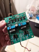
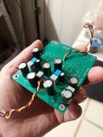
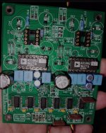
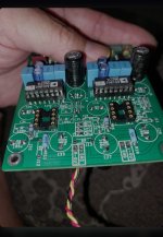
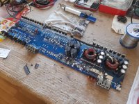
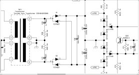
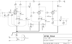
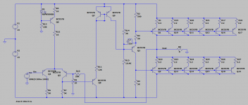
I guess for the fun. I didn't find a circuit around without transformers or coupling caps. Maybe its good to have on that day where they will stop making complementary bipolars :scratch2:

I have elaborated a first design with the BC557B which is a nice and cheap PNP transistor:
- Q6 is a current source for 2mA (R12 is the test resistor)
- Q4/Q5 are a differential pair for the feedback
until there, no problem.
- Normally after the differential, there is a complementary voltage amplifier. To avoid it, I put Q8 as emitter follower, and Q7/Q9 as current mirror. That way the voltage is transferred from the lower end to the upper end. The voltage on Q8 is converted to a current signal via R11.
- The output stage is from a 1962 book of a highly innovative transformer-free amplifier. I had a hard time researching for output stages without complementary transistors. After trying some designs, I understand why. A change in supply voltage requires recalculating the resistor values. Because the DC setpoints define these values, it can´t reach the full output voltage, in this case only ±7 of the ±15V. In addition some NTC must be added for thermal stabilization.

Some words on the design:
- Q6 current is 2mA (arbitrary)
- R6/R7 are 5K so the DC voltage along R7 is 5V with a swing of ±5V
- Q8 emitter voltage is that voltage plus 0.7
- The voltage on R11 is Q7 base voltage minus Q8 emitter voltage, or:
U11= (Vs -0.7) - (-Vs +5V +0.7V)
and the current swing is the voltage swing on R7 (±5V) divided by the value of R11. Here that means 2mA ±0,4mA. This sensitivity could be increased by placing a Zener diode in series with R11, because a voltage variation would then inherit a larger current variation.
- The current 2mA ±0,4mA is available on the collector of Q9. Q3 is a voltage amplifier. The design follows directly from the setpoints.
- Q3 base voltage is Vs - 2x 0.7 so 13.6V. The current through Q3 is chosen as 2.2mA.
- Q2 base voltage is the output voltage -0,7V.
- It is quite clear the design is not very clean, as Q1 is linked to the supply voltage while Q2 moves with the output voltage.

I would like to ask those people interested:
- At what point can this design be improved?
(This question is more on the general architecture, the stabilizing feedbacks and the thermal feedback can be added later).
- What options are available for the output stage?
(It seems the design is called totem-pole output and is used in tube amps and digital TTL circuits, but there are not too many information around concerning bipolar transistor amplifiers. Would a phase splitter with two independent voltage amplifiers bring any improvement?)

I have added the Spice schematic as asc and screenshot, and two simulation results. It works in principle, but not very well.

Thanks

Attachments

  • AllSame_Schematic_20200516.PNG
    AllSame_Schematic_20200516.PNG
    30.9 KB · Views: 2,115
  • AllSame_Result1_20200516.PNG
    AllSame_Result1_20200516.PNG
    10.4 KB · Views: 1,861
  • AllSame_Result2_20200516.PNG
    AllSame_Result2_20200516.PNG
    10.2 KB · Views: 1,819
  • PNP_amp V0.asc
    PNP_amp V0.asc
    6.9 KB · Views: 124
  • Like
Reactions: geraldfryjr

Uses for old output transformers

I've just found an old pair of Transcendar transformers I put aside a number of years ago.

There's some slight rust around the perimeter of the transformers - what would be the best cleaning agent?

Here are the specifications:

5K to 8 ohms, Frequency Response 20 Hz to 90 kHz, Maximum DC Bias Current: 90 mA, Primary DC Resistance: 370 ohm, Primary Inductance: 40 H, Part Number TT-012-OT

Any suggestions for a simple PCB based tube amplifier that would be suitable for a shed/workshop style set up?
Projects by fanatics, for fanatics
Get answers and advice for everyone wanting to learn the art of audio.
Join the Community
507,646
Members
7,882,617
Messages

Filter

Forum Statistics

Threads
405,961
Messages
7,882,617
Members
507,646
Latest member
joveaaron