Condenser mic jFET pre-amp design

Hello

I'm certainly not an expert with LTSpice but many years an electronics designer ..

I'm doing a hopefully low noise jfet pre-amp for the 34mm condenser insert I just bought but not sure if I have LTSpice doing the right thing, it's reporting an unusually low-noise level on the output of the pre-amp. I temporarily have the input 1G resistor set to noiseless to get a noise floor level on the pre-amp itself, but the noise floor seems way too low for the humble 2N3819 to me, the gain of the pre-amp is only *9 to *10 voltage gain, but that ought to be enough for input to a 24-bit 100dB+ S/N ADC.

The aim isn't for best THD etc, the desire is to get the lowest noise floor with the available parts we have laying around here. Spending £30+ on digikey etc just for a single low-noise op-amp design is not desireable (at present).

Any ideas what I might be doing wrong with LTSPice ? .. it's a new install with default everything.

noise_floor.png

Attachments

What should I do with these transducers?

Hi All,

I bought a couple of these old transducers a few years ago at an electronics surplus store. At the time, I was thinking I could use them for DMLs, but I'm afraid DMLs won't pass WAF muster. Any suggestions for how I can discretely incorporate these into my system? I'm thinking bass augmentation for my Frugel Horns w/ MA Alpair 7As...

Attachments

  • IMG_3058.jpg
    IMG_3058.jpg
    64.4 KB · Views: 72
  • IMG_3059.jpg
    IMG_3059.jpg
    76.8 KB · Views: 76
  • IMG_3060.jpg
    IMG_3060.jpg
    87.7 KB · Views: 71

two tube amps with same power rating/class/topology, but differing loudness?

I have two amps (ignoring the brands to avoid bias, but they are both known and credible brands) , 5 watts, with push-pull 12bh7 cathode biased power amps.

Actually one is marketed as a class A amp, the other doesn't say. Yet the latter is louder. Not incredibly more loud, but quite noticeably so. As I bought the class A amp B stock, I am getting paranoid that the output transformer is damaged. I have run into that problem before many years ago. The amp sounded fine, but power was very low. Replaced the output transformer (I don't even know how I managed, as my electronics knowledge is extremely low, I am just a musician) and the amp came back to life (loudness wise).

So what I am asking is, is it possible that the 'class A amp' doesn't sound as loud simply because it's a different design? Thanks.

Built a pair of functioning Chinese JLH 69 kits. What would you do next to improve?

Thank you again to everyone for your help on this.

I know my low-powered JLH amp has plenty of room for improvement. Does it sound like I'm getting sucked into this hobby? 🙂

- Should I replace my 12V laptop power supply with higher voltage/amperage? Is the JLH69 amplifier sensitive to power supply differences? In other words, is there any difference between internal (like a toroidal) vs an external (like a nice laptop-type) power supply?

- Is a JLH circuit like the one I built sensitive to component quality? Would replacement with tighter-tolerance resistors/caps/etc make any sonic difference?

Help: Ian Canada flagship streamer not working

I have recently purchased a series of Ian Canada products, to build a flagship streamer for my non-oversampling DAC (LAB12 DAC1+). The streamer consists of:
  • StationPi Pro
  • LinearPi Dual
  • Salas L-Adapter
  • 3 UCConditioner MkII boards
  • FIFOPi Q7
  • TransportPiAES
I have put (almost) everything together, apart from the 3 ultracapacitor boards, which will be placed and connected after a few days.

I am using Gentooplayer with Logitech Media Server, Squeezelite and Qobuz.

Although the system works fine, when streaming directly from the Rpi4 USB port (positioned on the StationPi Pro board), the IAN Canada stack does not send music to the DAC, when the TransportPiAES is connected via the SPDIF coaxial cable to the DAC. All lights of the various Ian Canada cards light up as expected, and the streamer 'locks' fine with the DAC, when the SPDIF cable is connected (see photo with arrows).

Initially I used the 'IanFifoII' DAC in GentooPlayer. But I have also tried other DAC options, but without success. I am not sure whether I have a hardware (FifoPi Q7? TransportPiAES?) or software problem (GentooPlayer?).

Does anyone have any suggestions about what might be wrong and what I should test?

Thanks in advance for the support.

Panos
Athens, Greece

Attachments

  • IMG_9899.jpeg
    IMG_9899.jpeg
    372.5 KB · Views: 287
  • IMG_9906.jpeg
    IMG_9906.jpeg
    399.1 KB · Views: 227
  • IMG_9909.jpeg
    IMG_9909.jpeg
    421.7 KB · Views: 223
  • IMG_9910.jpeg
    IMG_9910.jpeg
    361 KB · Views: 231

How I made a simple Remote On/Off for my Hi-Fi

My simple solution was to use an

AC Power Relay that was able to be triggered with a low voltage.
https://dlidirect.com/products/iot-power-relay

A simple IR remote-controlled relay for the control.
https://www.amazon.com/dp/B0BNBNF5MJ?psc=1&ref=ppx_yo2ov_dt_b_product_details

A cell phone charger to provide the needed 5VDC for the
IR Module and the triggering voltage for the AC Power Relay.

I mounted the IR remote-controlled relay in a small plastic box and
put the AC Power Relay and Charger behind the Hi-Fi and out of sight

A simple solution, and fairly clean.
  • Like
Reactions: invaderzim

Troubleshoot HTPS 7000

Hi all, I need some help trouble shooting an HTPS 7000 MKII. This is isolater/filter that has multiple uses. It arrived two days ago and doesn't power up. Generally, it is pretty well built. I removed the top cover and didn't see anything immediatly that stood out. However it does have a strong electronic smell around the main power supply board which resides by the two torroids. It is not an ozone smell, rather a deeper type burnt smell also like a burn in smell. Now I"m wondering if the chips are fried in it.

Put it on a variac and added a fuse to F402. plugged it in and attempted to turn it on. Fuse blows. A few more times attempting to isolate the problem. Completely isolated the P/S board and the main fault lies there, somewhere. Currently I have it where I can keep it from blowing a 1 amp fuse in the F402 position by putting a 100 watt bulb in series with the unit. At about 15 VAC the bulb starts illuminating and remains that way up to 120 VAC. I don't want to keep it that way so I tried to find the fault at 30 VAC so far haven't found it.

There are a lot of little chips that not easily accessed with the unit assembled. So I'll have to pull the board again for testing. My guess is one or more of the chips is shorted but not sure which one and don't have a schematic. The manufacturer, Monster, refused to provide me with a schematic as it is not their policy, they stated they won't fix it. I tried to explain to them that is what I was going to do, fix it and need a schematic. I've not had problems obtaining schematics from other well known companies, Fluke, HP, Mesa, Fender, Peavey, etc. So it will take some time for me to get up the learning curve. Here are some pariculars

Power Board: PC Board T2, 7000 MKI Issue 1, REV 1 Here is a list of the chips: Philips 5349 MOC3083 MJE13005F JC448 L78L05 1N4742 MPSA42 Mystery 7MK2-T142 (looks like a quad opamp?) The Zeners 1N4742 look to have been over heated as they are no longer orange and black but grey silver. I'm going to try searching for data sheets. I am not here to bash anyone or any thing. Just documenting what I find and how to go about fixing something that might be of help to others in the same situation. Anyone with experience with these units I would appreciate some assistance and guidance.

Thanks in advance.

I have some Pics and I post as I can get them out of the camera, alsways a challenge. iPhone pics while convenient are typically blurred for some reason. Here are pics of the unit.

Front:
001_7000Front.jpg


Top down view:
002_TopInside.jpg


Board view:
003_PSBoard.jpg
]

Board back view:
004_PSBoardBack.jpg


The back of this board had crap all over it. I wiped it clean with ISO-OH. It cleaned up nice and shiny while the wipes were brown. Smoke from something that burned or was it Tars from being in a smoke filled room? Doing some basic measurement with the board removed: Upper center board: Two 5W Cement resistors 62K and 39K measured abnout 1 ohm. The diodes and the resistors didn't read correctly.

The diodes read in both directions, .547 on the resistor check and 1.08 the incorrect direction. Pulled one leg up on each, and the resistors measured properly. Do did the diodes. I replaced the diodes just in case, didn't need to because the new one measured the same when installed. Next came the the two watt resistors to the center right. These were 330ohm and 560 ohm wired in series. 330 ohm were find but when checking 560 ohm they were both open.

Pulled a leg each with the same result, open. Removed them and meausred them. 560 Ohm each. WTF over? Turned my meter off and on meausred 560 ohm. Decided to replace them with 600 ohm 2 watt dale wire wound that I had on hand. Reinstalled board, same result...still have the burning 100 watt bulb. Found some of the problem by letting the unit warm up. It appears the MJE13005F and the JC448 are the problems as they are both on a heat sink. at about 15 mins at 60V with the 100 watt bulb...the heat sink burns to the touch.

It might also explain why have have AC on both sides of F401 fuse when the fuse is NOT installed. I don't know why they fried though and that worries me. Wondering what else they take with them? 1N4742 zeeners show signs of heat problem. More pics soon. Update on Data sheets: Philips 5249 is a BT136 Triac, 600V 4 Amp. JC448 my bad is a MJE13003 or 2SA1709/2SC4489 NPN my guess is the MJE13003 and/or 2SC4489 NPNHV Switch. 700Vdc peak, from Ic 1.5 Acd, Ib .75 Adc, Ie 2.25 Adc continuous. MOC 3083 is an opto Isolator powered by 240 VAC. 4n35 are opto couplers w/input to output peak @ 3.55KV. The specs on these are pretty beefy though. These things are pretty beefy, I hope it isn't that quad opamp that fried.... Light of my life:


005_PSBoard_Light.jpg


005_PSBoard_Light.jpg


Voltage Reading:
006_PS_Light_Variac.jpg


Focused Board Closeup:
007_PSBoardFocused.jpg


Update, Well as long as I'm here and going to pull the board again might as well shot gun it. First though I'll pull the mystery chip...just to be sure and then see if it still pulls current. That will rule out that part of the PS I'm thinking. Then, I'll pull the SS units and go from there. NOTE: When you link pics from the Gallery here for some reason I don't have ability to zoom in. : ( I was wrong again on some of the parts. Some of the parts I couldn't find readily but will substitue some of them. For some of the parts I wonder if it hasn't been already replaced with a lower speced part before I got it. I don't know. As I don't have a resource.

"small" vented horn project

Hi!

I want to build a bass bin! My excuse is i need more bass extension for my synergy horns to listen to music. And i thought maybe maybe it could run as a kick in between the synergies and my 15" TH at parties. That is, it is my third project, it absolutely is not necessary to make it as complicated as you are about to witness, but i'd like to figure this out.
Conditions are:

  • doesn't need to run terribly low, tuning around 45Hz, as i am many direct neighbours and flatmates.
  • should be smaller than the tapped horn. decided to go with about 60/40/30cm
  • high efficiency of the horn in the kick region for nice transient response and to be able to use it with the tapped horn (as an experiment at least).
  • i already bought a mivoc awm 104, seemed to fit well for that project

This is what i came up with:

schematisch 3d.png
schematisch plan.png


The port is oriented like that to be able to reach the driver from the top plate.
What i am unsure about is:
  • is this how you take the ground extension of the horn path into account?
  • how to make sure the BR-port is tuned correctly with the expansion at the end and the kink at the inside.
  • am i an idiot? 😉

i'll put my simulations in the next post.

Is this 12BH7 amp cathode biased or fixed biased?

I am just a musician, but usually with cathode biased amps you only see a resistor for the bias, not a trim pot. But this amp is similar to other cathode bias amps, i.e. 5 watts amps with a 12bh7 in the power amp. But it has a trim pot for the bias (page 2, on the right of schematic). Is that a cathode biased amp with a trim pot to get the cathode resistor into a wider range? Or is it fixed bias with a trim pot? I have this amp and on first guess it sounds like a cathode bias amp (the power amp distortion is spongier and sweeter than usually on fixed bias amps, which is harder. But I might be wrong, and maybe this amp is fixed bias and just sounds and feels the way it does.) Thanks.

Attachments

Sourcing the transformer from Orange Terror Bass PSU?

Hello people,

I m an electronic repair hobbyist who learning more and more everyday. I enjoy putting myself in bad situation and the one following is the worst i had to deal with when it comes to electronic repair...

The last broken unit i purchased is a Terror Bass amplifier, the 500w version for around 70 euros. I knew it was for parts but i was not aware someone tried to fix it.. and it's a mess cauz the transformer from the PSU is (almost) missing in the unit, only the ferrite is left (good condition) and 2 turns of one of the windings... The rest is bad but fixable : bad power transistor cross reference put in place, awful soldering.... The main problem is this tranformer.... 🙁

On internet, i can see the transformer is labeled TB500 from Yuyao Huachi... and luckily there is a schematic online for this amp..

I contacted Orange Amp with no answer yet... the product is out of warranty and buying the whole PSU would not make sense as it's over 500 euros so way too expensive.

I would like to know what you think about this ? Is it game over ? If im correct its a half bridge transformer with 2 primary and 3 secondary windings..

Im a bit stubborn and i love learning new things about electronics, i could go for building my own transformer but i think its far from being easy...

Thanks for your advices 🙂

Attachments

  • dscf3157.jpg
    dscf3157.jpg
    355.6 KB · Views: 88
  • orange_tb500_bass_terror_sch.pdf
    orange_tb500_bass_terror_sch.pdf
    355.5 KB · Views: 74
  • Capture d’écran 2024-01-16 à 18.23.18.png
    Capture d’écran 2024-01-16 à 18.23.18.png
    29.7 KB · Views: 94

Anything wrong with fixed grid bias?

I am currently pondering different biasing schemes for an estat headphone amp using DHT output tubes in push pull configuration (see here for a very early concept drawing). Looking at many posts, blogs and websites I found a lot of information about good old cathode bias (be it with a simple resistor or something slightly fancier like a LED). There is also filament bias, which is also a form of cathode bias, but does away with the high impedance cathode resistor. However, it consumes a lot of power and dissibpates a lot of heat.

I couldn't find much about fixed/grid bias (except maybe Valve Wizard). Why does grid bias not get more love?

My current thinking is that fixed bias would be a nice biasing scheme for my application because it provides the following advantages:
  • It's easy to adjust bias for various tubes (so the amp could work with slightly different tube types)
  • The cathode can connect directly to GNC/B-, so there is no need for a cathode resistor at all
  • Bias current is essentially zero, so it should be easy to minimize ripple and noise on the grid DC bias voltage
Disadvantages:
  • Grid bias requires a dedicated power supply (oh well, should not be a big deal)
  • what else?
Is there any drawback of with fixed/grid bias? Am I missing something?

attenuating a solid state guitar amp

is it safe to attenuate a solid state guitar amp with an attenuator/powerbrake (with line out) for tube amps IF the objective is simply to get a line out signal at the power amp level? That is, I am NOT using the attenuator to push the amp hard, but only enough to get the line out signal from the powerbrake. The amp is a hughes & kettner hybrid, the amp has two power transistors tip 147 (schematic shows on page two, bottom right area).

Any thoughts? Thanks!

Attachments

2 speaker designs - compare and contrast

For your comments:

I have two speaker concepts I'm working on, and I'd like to invite your comments on each given only a single point measurement for each with no further info on the designs. In particular I'm interested in the way each interacts with the room, as observable in the impulse response and the wavelet analysis.

Measurement conditions:
Mic at 1 meter from the tweeter diaphragm, centered on the tweeter axis. Dayton EMM6 mic, hand traced cal file from the supplied printed curve (before cal files were available electronically), Motu M2 interface with loopback into REW.
Measured in my small den, which measures 14' x 11' x 8' high, with the DUT and mic as far from the walls as I can manage but no additional acoustic treatment (no pillows on the floor, etc.).
The measurement level for each was reported as 86 dB in REW, though the level of Speaker A looks maybe a dB lower. FR is displayed with an 8 ms window for each, 1/48 octave FDW.


Here are impulse and FR graphs for the two speakers:
A impulse FR.jpg


B Impulse FR.jpg


And the wavelets:
A Wavelet.jpg


B Wavelet.jpg


I will attach the .mdat file with both measurements should anyone want to take a look.

Clearly reflections and in particular floor bounce dips are visible in the response. What I think is interesting is the difference in the number and strength of the delayed energy as seen in the wavelet. Would you expect one to sound 'cleaner' than the other based on this measurement alone? What else would you observe? Any interpretation or comment is welcome!

Bill

Attachments

NYD one bottle preamp questions

Hello
I'm building this preamp inside a roberts Akai unit.

I built using parts on hand that were close to the needed values and it worked very well, and sounds good, so I bought all the correct bits.
However I have a couple questions if someone doesn't mind indulging me.

Why is the output cap so large (3.3uf) when the cap between the stages is comparatively small (.02) ?

I have some .22 high voltage orange drops needinga home. Coul they be used in the output application?

And is there any advantage to using a larger cap (say .1) between the stages?

Thanks

Attachments

Driver recessing - how important? And does it cause people to avoid DIY?

My understanding of the theory is that:
  • low bass, it doesn't matter for those frequencies - a few mm (or even edge reflections from the cabinet) don't matter much
  • frequencies in the midrange and up where the driver is not beaming may be impacted by an effect from the driver's own flange, and also any other driver that is 'nearby' - especially if a bass or midbass has a deep flange
  • can impact midrange and also tweeter

Its not obvious however to what extent I should care if:
  • I have a (sub)woofer cabinet below the mid/tweeter and there's a cabinet break/step?
  • I have a stepped cabinet (Troels G does this quite a lot it seems) - I'd expect so but maybe time alignment trumps it
  • I have a largeish coaxial driver and upper midrange upwards is already bouncing around like anything - none of them (or full range) seem to have smooth trebble on axis, albeit off axis suggests that sound energy is more linear
  • I have a surface mount driver with a tapered flange (I'm thinking GR Research and perhaps other Peerless India customers [guess!], but access to a 3-printer could probably make an adapter for arbitrary small drivers)

It seems to me that for ease of construction, having to make a hole sufficient for the basket or tweeter magnet system - but not necessarily tidy, or even exactly the right size - has a lot of advantages. One might even use a jigsaw, for example, and any untidiness around finishing veneering or PVC wrap is coverred up too.

Troels G seems respected despite many designs having stepped baffles. GR Research seem to do OK, though I suspect a combination of a recessed tweeter and a surface mounted driver can yield a closer driver spacing.

I know there will be diffraction issues from the cabinet edges and no practical roundover is likely to make much difference. Would we just better not obsessing about it, maybe add a bit of felt? Don't see that very often these days.

Suitability of midrange driver for open baffle

Hi Thanks for readings. In a 3-way open baffle speaker it is recommended to use a bass driver with a high qts, 0.7 or greater to ensure good bass response.

Are there any specs to ensure suitability of a driver for midrange duties, over 120hz - 3khz. Low qts is supposed to give a more snappy mid, so is a low qts specification necessary, or are there any other specs to be taken into consideration

Tube pin straightener 3D print

In the spirit of DIY I finally created these two files for 3d printing your own pin straightening tools. They may look like sliced carrots but they are indeed petg plastic. Material type shouldn't really matter, I just happened to get my new printer tweaked in for the higher temp petg filament. They're pretty sturdy with 20% fill. Enjoy :drink:

Attachments

  • B7G.zip
    B7G.zip
    34.6 KB · Views: 68
  • B9A.zip
    B9A.zip
    42.2 KB · Views: 61
  • IMG_3526.jpg
    IMG_3526.jpg
    328.7 KB · Views: 119

Sugden A28 II bias problem

Hey there, I lately rebuild a Sugden A28II, after i recived it with several burned resistors in the left channel, but also defective transistors on both.

After rebuild everything worked fine, but I probably messed up, setting the left channel bias way to high, so one of the output transistors blew up.

Since, i again changed every transistor, diode and capacitor, even if they wasn t defective as I measured them.

But I can t adjust the bias, it is at a constant high of 1,2A and rising, till it blew the transistor which is marked in the scematics.

Could anyone help ?

Attachments

  • fc7adcfa-bb48-49ee-bf4a-835098d8927c.jpeg
    fc7adcfa-bb48-49ee-bf4a-835098d8927c.jpeg
    459.1 KB · Views: 192

Compression driver phase plug repair

Hi, i‘m repairing old Radian 835 CDs, however i‘m struggling a bit with the phase plug.
It has come loose on both of my units and i‘m a bit hesitant to glue them back in. Dry fitting them they seem to sit way too low, it‘s certainly a lot more distance to the diaphragm than what‘s written in the service instructions (.5mm). Also when the glue fell off the plastic stubs on the plug i had the impression that it added some height. Unfortunalety i didn‘t keep the glue residude to measure the thickness. Also inspecting the edges where the plastic dome should go into the metal structure there‘s probably half a mm or more missing. I know it from other manufacturers that they note down the height of the assembly and diaphragm to match the distance with mylar shims, but the service bulletin just instructs to use whatever shims are included with replacement diaphragms (mine came without any).
Could it therefore be, that there is extra tolerance in the motor assembly, to be aligned and fillen with glue at the factory? Do you have any idea how i could do this myself with diy tools? I‘m already afraid to build some kind of a test device with a dial indicator or similar 🥲

Any help is much appreciated!

Attachments

  • IMG_7482.jpeg
    IMG_7482.jpeg
    248.5 KB · Views: 107
  • IMG_7483.jpeg
    IMG_7483.jpeg
    290.7 KB · Views: 96
  • Like
Reactions: CinnamonRolls

Open baffle subwoofer question

Hello Ladies and gents.....
i have a question related where to start from when choosing my driver for lower frequencies... i need it to cover bottom to 150Hz max....
.
thing is - my room is brick walls and concrete floor and ceiling (European homes).... 16m2 of area... not to big of a room.....
.
so i have been changing my mind between 12inch or 15inch and i am worried then one 15inch per channel would be to much when put it in a H baffle without active crossover - all passive....
so i am kind of more for 12inch and if needed, i can always put two of them (one on top of the other)....
the downside of the 12inch driver is that it does not go as low as 15inch....
so...
i was checking SB Audience bianco 12OB150 and compared to Monacor SP-382PA..... (they seem to be nice options for Europe - any better suggestions?)
seems that 12inch Bianco has better "air moving capabilities" even when compared to 15inch Monacor.... higher sensitivity also ... and is also a little bit lighter in weight of the membrane....
Donwnside is that Fs for Bianco is 44Hz and for Monacor 25Hz..... also Qts is a bit lower then Monacor (0.63 for Bianco and 0.75 for Monacor).....
....
Bianco 12OB150 looks better in some parameters but not so good in others - do i need my woofer to go lower then Bianco goes... do i need that much "air moving" in my brick/concrete room .....
if i go for Monacor, i will have it go low and with less SPL maybe it will do the job even better then 12inch Bianco in my room
...
What to take and start playing with .... that is the question now....
....
need to say also that i am listening to electronic music, blues, rock, experimental, acoustic, basically everything but classical......

For Sale Bryston BDP-1 streamer

Its a NOS unit, (see inside Pictures for no dust from no use) .i only used few months to play from local SSD disk, which It made smoothly, except for the moose software ,that sometimes hang to load file. Patience to simple wait self solve the issue. They Say Roon ready but never tried. At his time was extremely expensive and One of the First well built streamers. Much of info online. You control It from your smartphone by finding its network address. Digital output AES EBU or BNC coax. Sell for 450 Eur + shipping. Its 230V version for EU.
Will find a proper box to ship safely. Original(not a Copy) manual available.

IMG_20231217_193219.jpg


IMG_20231217_193204.jpg IMG_20231217_193034.jpg. IMG_20231217_193004.jpg IMG_20231217_192933.jpg

Germanium two stage pre

Hi all community. I found those pics in two different books from some decades ago. It's very simple: two stage germanium transistors (PNP) with the input base resistor bootstrapped and helped with NFB. IMHO too many lytics but not easily to save them.

Do anyone tryed it? Who is the creator (has a particular name)? Some other examples?

Attachments

  • 01.jpg
    01.jpg
    252.1 KB · Views: 168
  • 02.jpg
    02.jpg
    307.1 KB · Views: 165

For Sale ZOUDIO AIO4CH: 4-channel amplifier with DSP and Bluetooth - PARTS

I have a dismantled ZOUDIO 4-channel DSP board for sale. It is fully functional. Included with the board are a few of the flying lead cables, antenna mounts, RCA jacks, a couple LED cables and rotary encoder. This is sold as is and only includes what is shown in the attached pictures. This is not a complete, original kit. Useful for parts. Asking $20 plus shipping.

PM me if interested. Paypal ONLY.

Thanks,
Rick

PXL_20240118_145021240.MP.jpg
PXL_20240118_145028854.jpg
PXL_20240118_145050105.jpg

Noob seeking test equipment recommendations

My first DIY project will be to build new enclosures for a pair of Cerwin Vega AT-15s. As part of that process, I would like to be able to test individual drivers, crossover components, and the loudspeakers as assembled units.

My equipment currently includes a laptop loaded with REW, a UMIK-1, a Dayton DATS V3, and a digital multimeter.

What other equipment and/or software do I need in order to optimize the performance of the AT-15s?

Thank you for your recommendations.

Accuphase DP-70V: TOC read in a glance, first track not played

Hi Community,

I’ve recently acquired this amazing player in an almost perfect shape where the vast majority of my CD collection is read perfectly and track skip usually happening in a couple of secs.
That said there is an handful of disks that, despite their TOC is read in a glance, the first track takes forever to start.
Lens has been cleaned, linear guides have been greased but those few CDs really hurts.

I’m keen to think of the focus bias non being perfectly set but given the lack of a service manual I can’t even look for the RF pin

Any suggestions? On the pick-up I see the typical APC the TB and the FB triggers.

Thanks for any hint you’re willing to share
IMG_0220.JPG

Arcam A85 i need help picking a new fuse. Resettable or non Resettable?

So i recently got my hands on a Arcam A85 and A80

the A80 work fine (little testing)

All was good and working with the A85 (turned up loud wanted to see what it could do) till i plugged it in for some fun a week later and it had no signs of life no standby light nothing and wont turn on i did some digging and found it to be the 750mA surface mounted fuse on the PCB (i bypassed it with some tweezers) and it came back to like then i turned it off after a sec or 2.

now my big ask is do i replace it is a regular fuse or a resettable one?

non Resettable : (HERE)

resettable : (HERE)

it was in a very very damp/humid room for one night although i had my cd Player and 2 other amps and a pc in there and they were fine so idk.

the Arcam service manual only says 750mA nothing else i thinks its on a 5v or 9v psu so i guess anything above that is fine?

Side note:
the A85 tone controls also don't work if you mess with them then move the volume the tone changes like if i put -1 bass then turn up and down the volume the bass and treble will change up and down and make cracking noises.


Really appreciate any help thanks!

How I built a high quality multi-room wireless sound system for less than 200$

How I built a high quality multi-room sound system for less than 200$​

This is my first project using Arylic products. My goal was to build a tailor-made multi room sound system for my new apartment using my existing speakers:
  • a pair of passive Beovox S4500 from Bang & Olufsen (without amp)
  • a pair of active Yamaha HS3 which I used to produce music with
My vision of this project was to use vintage Beovox Bang & Olufsen speakers which I found on an auction for my living room, and my HS3 for my work station in another room. For a long time I thought this would be impossible. I thought I would have to invest in new smart speakers to get a multi room experience, such as Sonos which are already designed to connect to the network of your home. But then I found out that Arylic have a great DIY amplifiers and products designed for this purpose.


Pic1_beovox
Beovox S4500 from Bang & Olufsen


Pic2_yamaha

Yamaha HS3

First I setup my Up2Stream Amp V4 with my Beovox in the living room. I have easily connected my two speakers to the board using the authentic B&O wires (you just need to cut the edge to divide the wire into two, which is equivalent of having one black and one red wire for each speaker). These are the white cables you see connected to the green cube in the pic below. And on the left of the green cube, connect to a 12V power charger.

You can choose with a switch on the amp between either Mono/Stereo. I have it switched to stereo mode and then built a nice transparent plexiglass case to avoid accumulating too much dust on it.


Pic3_AmpV4

Up2Stream Amp V4

The challenge was also to be able to use them to connect my turntable using bluetooth. With the Amp v4, I can switch between Wifi and Bluetooth very quickly using the remote control, or simply by pushing the dedicated switch button on the backside of the amp. I can now enjoy listening to my vinyl collection using my sound system, or watch a movie with high quality sound connecting it to my smart TV (this works the same way with any bluetooth unit you want to connect).


Pic5_BeovoxVinyl

Vinyl player and smart TV connected to the Beovox

Then I’ve setup my Up2Stream Mini V3 with my Yamaha for the workstation. My Yamahas are active speakers which means they already have an amp integrated in them. I have connected the Mini V3 using a jack cable (as seen in pic below) and simply connecting it to a USB C power charger.


Pic4_AmpV3

Up2Stream Mini V3

To finish, how do I connect the multi room?

Now I’ve got both my living room and workstation setup. To enable a multi room experience, I download the 4stream app available on IOS and Android. I used the app to connect my amps to my WIFI network and setup a name for each of them (in my case . Once that is done, one can simply use the interface to control all speakers. Either you want to use them as multi room system or as separate ones. I can even control the loudness for each of the speakers to have louder in one room and a lower volume in the other.


Pic6-7_4streamapp

4stream IOS app & Spotify Interface connected to Beovox

In conclusion, you can build a multi-room sound system for less than 200$ very easily with high quality speakers.

List of products:

Arylic:


Other suppliers:
  • 12V power charger, ca. 15$
  • USB C power cable, ca 10$

For Sale Genuine Hitachi 2SK1058 & 2SJ162 (not renesas)

I have 38 pairs of these, NOS condition.
(30 pairs still in their anti-static tubes).

Selling them for $16/pair + PP fees + Shipping (min buy 4 pairs).

Estimated Shipping: $8 to EU & $10 to the US/Canada (up to 8 pairs).
Other countries please ask!

PM me if interested

Thanks

Attachments

  • Screenshot_20240117-160235~3.png
    Screenshot_20240117-160235~3.png
    577.8 KB · Views: 141
  • Screenshot_20240117-200820~3.png
    Screenshot_20240117-200820~3.png
    263.8 KB · Views: 136

Dumb idea... corner-loaded open baffle

So, I was futzing about on the interwebz, looking at single-driver designs, and I ran across the Jordan Triangular Array design. And I thought to myself,

"Self, Our small living room requires speakers to be placed in the corners. Corners are triangles. I have basically no woodworking skills. Hmmm..."

So, what might happen if I cut a triangular base to fit the corner, and put a vertical board that would fill the gap, so that the corner would make the rest of the triangle. Then put a single, (or maybe double) pair of full-range drivers in the upright part. Basically, using the room corners as the other 2/3s of the enclosure. But with a semi-open, kinda-sorta-dipole backside.

And then I thought, "This can't be a new idea, because there are very few new ideas. Somebody must have tried this."

So...

Has anybody tried this?

--Shannon

Selling Zhou Fang’s remaining stocks including some very rare Toshiba transistors--moving out sale

Hello everyone,

Greetings from LiubinCalvin. I've been away for some personal endeavors. Recently, while relocating to my new residence, I came across a significant collection of devices stored away. In an effort to declutter, I've chosen to host a flash sale.

I discovered a substantial amount of devices in my storage room. To free up space, I've decided to hold a flash sale.

Terms & Conditions:

  1. Due to limited time for packaging, the minimum order amount is set at $100.
  2. I aim to dispatch parcels approximately once a week. Your patience is highly appreciated.
  3. All items are 30% off. For orders exceeding $300, you'll receive a 40% discount.
  4. For items sold as matching pairs, the provided data is based on my previous measurements. Unfortunately, I don't have the equipment to re-measure them, so only the existing data will be available.
  5. If anyone is interested in purchasing my entire remaining stock, please get in touch and we can discuss a bulk deal.
  6. Payment via my PayPal account.
  7. Other T&Cs in my old post are still effective
To see what's available, refer to my previous post. I'm immensely grateful for your continued support. Wishing you a fulfilling DIY experience.

https://www.diyaudio.com/community/...ng-some-very-rare-toshiba-transistors.291486/


A gentle reminder: It's important to clean the metal legs of devices before soldering them onto the PCB or performing any tests. The humid conditions in Singapore might have caused some rusting on these metal legs. Unaddressed, this rust can result in poor connections between the metal legs, the PCB, and the solder. For effective cleaning, using sandpaper or a knife is recommended.

Please inform me if there are any issues. 🙂

Switch to bypass pre-amp gain stage

Hi Folks – I’m rebuilding an old pre-amp and want to add a switch to bypass the gain stage leaving just a buffer with unitary gain when switch is on.

I run multiple dif sources and power amps off it and many of the combinations don’t need the preamp gain – basically it just seems unnecessary in these cases to attenuate the majority of the signal (by turning the vol right down) just so the preamp can them amplify it back up again.

The circuit is attached below. Basically, it is a cathode follower input buffer, cathode-coupled to a non-inverting gain stage with a cathode follower serving as an output buffer.

My initial instinct is to inject the signal (via a switch) to the plate of the second triode to bypass the gain stage and just leave the output buffer.

Will this work? I’m guessing I will need at least a coupling cap to block DC from flowing back to the source?

It has also been suggested to me that i could bypass the feedback resistor to provide 100% feedback and therefore unitary gain – is this a better option?

My circuit knowledge is a bit basic – so be gentle!

Circuit.png

Looking for a reasonable second build after C-Notes

Hello everyone,

About a year ago I built a set of C-Notes last year from a flat pack kit & painted/veneered them. I enjoyed the project quite a bit and the speakers have treated me quite well as the primary speakers in my apartment living room.

I'm itching for a winter project and would like to take on something a little more complicated. I have access to woodworking tools, so I am able to build my own cabinet. I would like to make a second pair of speakers for my room/office to listen to music while working from home. I'm a bit torn between going for some tower speakers for the living room & moving the C-Notes to my office or building another set of bookshelves and keeping the C-Notes where they are.

The more I research the more I realize that beyond entry level DIY kits like the C-Notes there's no clear "best" DIY kits in my price range of $300-600. I see a lot of comments that in 2023 it is harder for DIY to compete both on price with commercial offerings and technologically e.g. in terms of dispersion. I'm no expert so I'm not sure how seriously to take those claims - part of the value for me is the enjoyment and learning I get out of the project. I like good sound but I'm hardly an audiophile.

Some speakers that have piqued my interest and which I'm curious to hear opinions on:
  • Amigas - Right now on sale for $300 w/ baffle only at Parts Express, which is enticing. I've heard some criticism that the design is outdated, but it also seems widely built.
  • Speedsters - Ribbon tweeter is interesting and folks seem to enjoy the sound profile a lot. A bit expensive right now since no full kit exists.
  • Hivi 3.1A w/ Sehlin mod - On paper looks great.
  • CSS 1TD - Higher end on price but seems to get rave reviews & has upgrade path to 1TDX.

Any other suggestions are appreciated!

Sunn Beta Lead 100, replacement pots

Hi guys.
I have a Sunn Beta Lead, and I'm wondering where to get these particular potenciometers for this amp. For example, the "drive" pots are 1 Mohm dual gang, with the 3 pins of each gang assembled 180 degrees opposite of each other. And the rest of them are 100k pots with a 4th pin to each one. They are beginning to fail on location, and make a crackling noise, and I just cleaned them with contact cleaning spray.
Any ideas where to buy them? Or a complete set of new ones (13 pots in total)?

ESX Quantum QE 900.4 continuously draw current

Hey,

i have a problem with the esx qe 900.4.


I replaced the power supply fets (IRF3205, the original ones were other fets), gate resistors to 47ohm and the corresponding 8 SMD transistors for controlling the power supply fets.
Also channel 3 output fets, TIP35CW and TIP36CW, because the batch was completely different. (someone has already tried to repair it)

Amp works, rail voltage +- 42v also fits, all channels play music/sine without problems and without distortion.

The problem is the constantly increasing current. Good to see on the laboratory power supply unit.

At 14.4V it is 2.3A idle current. Then the current slowly increases, normally not a problem when the amp warms up and bias sets. But it does not stop drawing current. After 15 min the idle current is already at 4,2A. In my opinion, that is far too much. Music continues play without problems. The amp does not get very hot, except the MJE340g and MJE350g. output fets and ps fets are all within the normal temperature range.

Unfortunately i have no idea how to set the bias on these amps, or rather i assume that bias is set "automatically" here. (bias-circuit in the photos)

Does anyone have any idea what is slowly but steadily drawing current here? If I set the voltage to 11v or 12v, it holds it for a while, but then also rises, only more slowly.

(I am still surprised that the oscillation frequency of the power supply is 52khz and not ~25khz as usual)

Attachments

  • IMG_9673.JPEG
    IMG_9673.JPEG
    661.2 KB · Views: 117
  • IMG_9706.JPEG
    IMG_9706.JPEG
    711.3 KB · Views: 93
  • IMG_9707.JPEG
    IMG_9707.JPEG
    735.4 KB · Views: 97
  • IMG_9708.JPEG
    IMG_9708.JPEG
    529.8 KB · Views: 112

Worth salvaging parts of a Sumo Andromeda II?

Hi folks,

I have some parts of a rev C Andromeda II that I bought from another forum member who was unable to repair the amp. I would like to resurrect an amp from what I have, but I'm wondering if it's really worthwhile.

What I have are the boards... missing some output transistors and source resistors, and the transformer. He used the case for another project, and said the filter caps were dead (I'm surprised by that, since the filter caps from my rev A are still good after all these years).

Anyway, I would need a lot: case, thermal switches, power switch, filter caps, connectors, fuse holders, internal wiring, output transistors, etc.

I would also, and first, I think, need to depopulate one of the boards, scan it, create a layout from it, and have new boards made. These boards are in pretty bad shape, with lots of broken or peeling traces and some fiberglass damage from overheated components.

Then there's the question of outputs... the originals are IRFP9243 (Harris, NLA) and IRFP250 (?) or 240... I think that more modern IRFP9240/IRFP240 outputs would be feasible, but I'm not sure. I have not yet removed and tested all the twelve remaining outputs. The two I did remove tested OK... one was an IRFP9243 and the other was an IRFP250 (but reports are that 240s were used in these amps).

Overall, I'm looking at probably $400 to build a new amp from the ashes of the original. The Andromeda II is rated 200W into 8 Ohms, and 350W into 4 Ohms. It would be satisfying to build an amp from the parts I have, but would it be worthwhile? I don't need another amp - I actually have two "spares" already.

Thoughts?
Cheers, Paul

Question about older MicPre SYMETRIX SX202

Hello,
I bought an older MicPre SX202 from SYMETRIX. Unfortunately it doesn't work properly. If I plug in a dynamic mic everything is fine. But when I plug in a capacitor mic, it hums very loudly with the phantom power turned off. When I turn on the phantom power it hums even louder. This is on both mic channels. On suspicion, I replaced all the electrolytic capacitors on the board, but that didn't change anything. Since this hum only occurs with condenser mics, but not with dynamic mics, I suspect a problem in the phantom power supply. I tested various condenser mics, which I also plugged into other MicPre for comparison. The cause of the humming lies in the MicPre SX202.

Can anyone tell me what this could be? Is there a "typical" component (other than capacitors) that could be the cause? Unfortunately I don't have a circuit diagram for this MicPre.

Maris

Trade my Iron Pre SE kit for your Iron Pre Balanced kit?

Hello,

With the last set of kits that were open for sale in the store, all that remained for me were SE kits by the time I realized so I went ahead and bought one. I won't get to this project for a little while yet, and I know that more kits probably will not be available again until middle of the year at the very earliest.

Figured I would throw this out there to see if anyone who maybe has a balanced version of the kit but realized or decided they no longer wanted the balanced version, would be interested in trading. I have a still unpacked SE kit and I would be more than happy to of course offset the cost difference with $30 your way as well.

I am looking for unbuilt balanced kits only, I would not be interested in any finished or partially built kits.

UPV - XMM IDS Error

Hi,

One of our UPVs is giving an 'XMM IDS error' - please see attachment. The menus in general appear to show somewhat garbled parameters. I hooked the B1 oscillator to one of our working AAs and it seems to be working in spec (as does normal oscillator). The issue appears to be on the analyser side.

As parts are likely to dwindle for these over time and R+S may well stop servicing them, I may well end up sending it R+S...but I thought I'd ask the brains here in case it's something obvious.

TIA

Attachments

  • PXL_20220705_132312065.jpg
    PXL_20220705_132312065.jpg
    478 KB · Views: 68

Hypex FusionAmp FA253 Built into a Modushop case

Hypex FusionAmp's FA253 Built into Modushop cases

Not too long ago I made the switch to actively controlling my speakers through the FA-253 Hypex FusionAmp's, after experimenting with various crossovers, I finally found a crossover that I really like, the result is in all areas clearly better than how the speakers performed with the passive crossovers.

It was therefore clear to me that active crossovers were now the way to go.

My beloved Audio-GD Master-3 PowerAmp was put up for sale and it was sold within a week, but I was now left with an empty space in my stereo rack and because I cannot install the FusionAmp's in my Mordaunt Short Performance 6 LE speakers because of the spherical backside of these speakers (apart from that it is of course a shame to deform these beautiful speakers forever !!), so I decided to disassemble the two FA253 and build them into aluminum cases that had to fit into the room who left the Master-3 PowerAmp.

After some searching on the net I decided to go for the black Galaxy 3U GX285 cases from Modushop.

The sequel can be clearly seen in the photos below, still need to assemble 6x 3 meter Supra Ply 3.4S cables, So for now the amps are placed next to the speakers.


One of the Mordaunt Short Performance-6 LE speaker


The now sold Master-3 PowerAmp


Fitting the still emty cases


Ready to be mounted


5 degrees above the room temperature, bottom plate on which the amps are mounted 10 degrees more than the ambient temperature.

Krell KSA-50S schematics

The amp works perfectly, but occasionally the left channel does not turn on and I read that both the relay and the electrolytic of the soft-start circuit are prone to fail.

Being an amplifier of almost 25 years, I think that in addition to repairing the soft-start board could change all the electrolytics and probably other components that do not look good.

But despite having searched a lot, I have been unable to find the schemes.

If someone has them, can give a clue as to where to find them, or can share any experience on this particular model, I would be very grateful.

Thanks,

Rod

Jeagam 8200

Greetings all )
So I imported this Mitsubishi Jeagam back in 2004 from Japan or China, I'm not sure anymore, and then I stripped it.

1705492254370.png


1705493192914.png


This is what a complete one looks like, pretty..... actually its hard to find an image of one becuse they were only sold in Japan.

1705492506503.png


I was clueless in 2004 and I'm only slightly less clueless now about loudspeaker parameters, so I need help choosing a 6.5 inch speaker for this please. I'm hoping for a speaker around 90 - 92db becuse my tweeters are 89db Morel MDT-12

I'm using a wondom Jab4 amplifier and that will serve as a crossover.

What 17cm - 6.5" woofers would do well in such a small space please? I measured the internal volume as 14.7 litres.
I'm not expecting miracles, just something with reasonable bass.

I will fibreglass the interior of the box to make it more rigid, like I did on the one below, and rebuild the face so it looks stock. Will be sweet.


1705492842230.png

Imaging tweeter... how about an 'imaging midrange'?

I read an article from JL Audio about using a secondary set of tweeters to help raise your sound stage (imaging tweeters). I've never done that, but it makes sense to me intuitively.

My current midrange drivers are about half way up on the doors with tweeters in the sail panels. They do the job, but...

Since reading that article, I've become obsessed with the idea of using an 'imaging midrange' in a similar way.

I have two small midrange speakers (Dayton RS75, optimal 600-6000k) that I have no other use for, and my A pillars have a perfect spot for them. I also have DSP capacity to control their level, time alignment, etc. I know there's potential for phase issues, etc.... but could it work?

I'd probably never recommend someone do this when planning a system from scratch, but I can't help but wonder if it would be possible or beneficial (fuller, louder, deeper, or higher sound in the midrange).

I've personally never seen it done (that might be my first clue that it's doomed to fail!). I'd just try it, but it'll be a bit of a PITA and a lot of wasted time if it's a dud of an idea (and I've had too many of those lately!).

I don't know... any thoughts about this? LOTS of you have bigger brains and much more experience, so I'm hoping you can save me some trouble, smack me in the face... something! lol

DIY phono preamplifier : earthing scheme proposition

Hello fellow DIYers !

I'm in the very last stages of my MM/MC preamp clone and I would like to validate the earting/grounding scheme before the PCBs get sent to the fab house. My design handbook states that the central point of a star-grounding arrangement for the whole system should be right at the most sensitive input stage of the amplifying chain to reduce the length of its negative terminal to ground, including the mains ground. That means the phono stage input in my case.

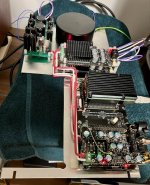
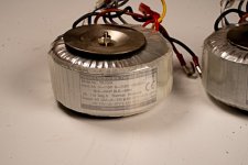
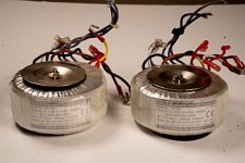
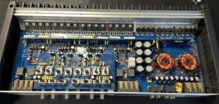
This build is kind of a "scrapbox challenge", re-purposing a TV set-top box steel chassis and a power transformer with EI-lams. A challenge as far as avoiding induced noise from the environement and mains ground but I know it can be done as I have a Rotel MM/MC preamp here that is built just like that and is dead silent. I use the same precautions Rotel did : shielding the power transformer and having the power supply as far as possible to the sensitive circuitry. I won't even consider a separate power supply chassis for this project.

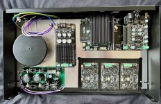
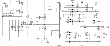
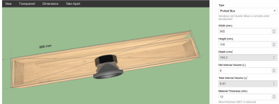
See diagram below. The main elements in the chassis are positionned at their correct place and about to scale.

Janus Phono Stage v.0.1 earthing scheme.jpg


Key points:

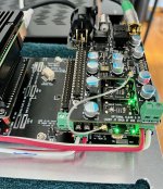
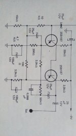
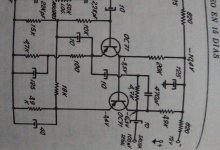
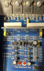
- The two PCBs at top right of the chassis drawing are identical amplifier circuits for each channel; It is a discrete BJT fully symmetrical bipolar design which helps in reducing common mode noise sensitivity.

- Since mains power is fed by transformer and as the output is capacitor-coupled, there are four "grounds" in the system: Mains earth, power supply ground, input ground and output ground.

- Input and output grounds are NOT joined on the PCB but rather their RCA sockets are tied together using a piece of bare copper wire. This is duplicated for both channels.

- Likewise, power is fed to the PCBs using two distinct sockets and their common ground is not tied on the board but routed to the power supply star point (screw terminal at bottom right). This power supply ground star point is then tied to both input/output RCA sockets pairs, from which point a wire goes to the main ground post.

- All AC power wiring is twisted. I may also twist the signal input/output wiring (not shown on diagram).

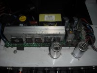
- The power transformer is rotated at 45° to the chassis corners for maybe a bit of magnetic field cancellation by reflection... Not sure if that's such a big thing but it is recommended in my handbook and made the layout cleaner anyways.

- The power transformer secondary has no center tap so the power supply ground reference point is set with two 1% metal film resistors (middle left).

- Two strips of copper-clad phenolic board act as a non-magnetic shield to the AC power and regulator sections. Each strip is grounded separately directly to the chassis' integral ground screw.

- Power supply and preamplifier PCBs sit on 10mm nylon standoffs with nylon screws to reduce possibility of noise coupling. If push comes to shove more copper-clad board pieces can be added below and over the boards to completely surround them with non-magnetic shielding.

- There is a manual link between the chassis ground screw and the preamp ground post. The preferred mode of operation would be to have the chassis ground separated from the preamp star ground, with the power amplifier ground screw tied to the preamp as the whole system link to mains earth. However if the preamp is used standalone and connected to a "floating" input such as a battery powered laptop for example, the ground link is shunted and the preamp mains becomes the path to mains earth.

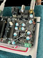
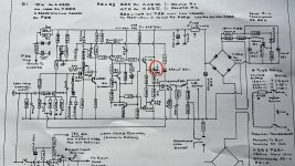
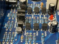
- The signal path is sketched on the rightmost board, and the leftmost board has a possible ground plane drawn. The existence and form of a PCB ground plane is still an outstanding question. Currently on the PCB the input ground signal is a star-ish arrangement of traces across the board (see net highlighted below).

Capture d’écran 2024-01-10 173449.png


The parts layout is quite packed and derived from the original preamplifier, which was on single-side PCB and used a lot of 0-ohm resistor links across the board. I get away with those by using a 4-layer stackup, taking care to cross superimposed traces at 90° and avoiding close paralleled traces.

In tutorials I see recommendations to place signal traces between two power planes, or at least over one ground plane, but the original implementation on single-side PCB obviously doesn't and still works, so I didn't place one. But should I?

If using a board-wide ground plane I fear that all those through-hole leads act as antennas coupling noise onto the ground, so that's why I sketched a possible shaped ground plane encompassing only the sections related to the input signal ground. In any case if the ground plane is needed it will be on the back of the PCB to further shield the signal and the chassis. Is this a better approach?

Sorry for the very long-winded post, this is my first phono preamp build and I wanted to be as precise as possible. I think I have covered all the bases, does that makes any sense to you? Are there obvious No-No-s?

As always, thanks in advance for any insights!
- Joris

For Sale Set 4x6H1N-EB NOS Tubes -rocket +OTK1

Can't Remember if i used them after purchase many years ago. Open to Fair offer. See pictures of you Need more coding info Just ask.

Attachments

  • IMG20240117104543.jpg
    IMG20240117104543.jpg
    438.9 KB · Views: 61
  • IMG20240117101701.jpg
    IMG20240117101701.jpg
    432.6 KB · Views: 70
  • IMG20240117101648.jpg
    IMG20240117101648.jpg
    400.4 KB · Views: 65
  • IMG20240117101638.jpg
    IMG20240117101638.jpg
    351.4 KB · Views: 61
  • IMG20240117101322.jpg
    IMG20240117101322.jpg
    478.6 KB · Views: 72
  • IMG20240117101232.jpg
    IMG20240117101232.jpg
    227.3 KB · Views: 67
  • IMG20240117101228.jpg
    IMG20240117101228.jpg
    241.8 KB · Views: 65
  • IMG20240117101123.jpg
    IMG20240117101123.jpg
    579.9 KB · Views: 74

B&W 802 Matrix S2 restoration

I did these up and sent the Crossovers to Wilmslow Audio to refurbish the crossovers as they felt necessary using Mundorf for the larger and Jantzen small capacitor values.
I don't trust my soldering skills unfortunately.
Someone had butchered the main bolts with a screwdriver so I restored them and made my own tool for turning them. And B&W had left the pressing marks in them which made them look a bit...... erm, not great so I flattened them properly before respraying
In addition I didn't particularly like speaker cloth on the cabinet tops so I used some special paint from the Plastikote range.

Attachments

  • IMG_20240107_132852.jpg
    IMG_20240107_132852.jpg
    266.7 KB · Views: 234
  • IMG_20240107_132953.jpg
    IMG_20240107_132953.jpg
    247.2 KB · Views: 289
  • IMG_20240107_133007.jpg
    IMG_20240107_133007.jpg
    289.8 KB · Views: 214
  • IMG_20240107_133621.jpg
    IMG_20240107_133621.jpg
    149 KB · Views: 220
  • IMG_20240107_133609.jpg
    IMG_20240107_133609.jpg
    210.2 KB · Views: 230
  • IMG_20240107_132826.jpg
    IMG_20240107_132826.jpg
    311 KB · Views: 216
  • IMG_20240107_132802.jpg
    IMG_20240107_132802.jpg
    438.6 KB · Views: 232
  • IMG_20240107_132840.jpg
    IMG_20240107_132840.jpg
    333.2 KB · Views: 220
  • IMG_20231229_131554366.jpg
    IMG_20231229_131554366.jpg
    298.5 KB · Views: 288
  • IMG_20231229_131639686.jpg
    IMG_20231229_131639686.jpg
    292.7 KB · Views: 231
  • IMG_20231228_210507.jpg
    IMG_20231228_210507.jpg
    624.5 KB · Views: 230

DSP-in-the-middle: CamillaDSP on RPi4 with 8 channel I2S inputs and outputs?

I have a 7.1 AVR that uses a PCM1690 DAC. It has some decent EQ capabilities, but I want to unlock the full potential of DSP by intercepting the pre-DAC I2S signals, manipulating them with CamillaDSP (or a better alternative?), and feeding that to the DAC.

I'm only using 3.1 speakers right now but I'm building my own 2-way speakers and I don't want to use passive crossovers. What I want to do is leverage the extra channels my AVR provides to power each speaker driver independently. The AVR configuration interface will not allow me to do what I want, so I want to intercept the I2S inputs, process them with my own DSP, then provide them back to the DAC. Digital in for DSP, digital out back to DAC, using the 7 amps provided by the AVR.

1699308687568.png


PCM1690 Datasheet

So my thinking is I can just desolder the resistors on each of the 4 inputs (each input has 2 channels I2S), solder on a wire on the left sides that connects to RPi4 inputs, then take the 4 RPi4 outputs and solder wires to right side of resistor pads, then use CamillaDSP on RPi4 to modify the signals. Then I can take the FL/FR 2 inputs and split them into 4 outputs (FL woofer, FL tweeter, FR woofer, FR tweeter) and use those amplifier channels differently from how they are labeled. Do the same for center channel too.

I found this cool video that describes something similar to turn an AVR into a preprocessor, but I would prefer to skip the SPDIF conversion if possible. I also have 4 data lines and not just 1 like his example.

I don't know anything about I2S, clocks, re-clocking, or really anything else here so I'd like some guidance on the best way to proceed. Ultimately it would be great to remove this DAC and replace it with something higher quality but for now, because of the ease and low cost, doing a simple DSP-in-the-middle hack with CamillaDSP seems like the best choice. There might be a better choice than CamillaDSP but this is what I currently think is the simplest and cheapest approach that gives me what I want. I noticed that some better DACs like ES9039PRO have customizable FIR filters but idk how to interface with that. CamillaDSP provides an easy to use interface so that's a huge plus. RPi is ~$50 right now, ES9039PRO is ~$100, so I'd prefer the new DAC if it came with a UI that is as nice as CamillaDSP.

So, how can I make these I2S inputs and outputs work with CamillaDSP on the RPi4?

Full range with HF CD/horn assistance

Has anyone had any experience with adding a hf CD/horn to a Markaudio A10p driver? I don’t want to use a crossover but I’m a noob and unsure if that’s necessary or not? I was considering using the B&C 110 or faital pro 107r & Faital Pro STH100.

Any recommendations suggestions advice is greatly appreciated.

Amplifier is 7w SET with 1ohm output impedance
  • Like
Reactions: Chemarcelo

Airborne FR222B8-19F

Does anyone have experience with Airborne FR222B8-19F full range driver? I'm thinking about trying them out in a vintage stereo console rework and have 2 main questions.

1)I'm interested if anyone has measured the TS parameters at home.

2)With the 5k dip, I'm thinking that after I shape the response above and below the dip creating a downward slope towards 15khz, the 5k dip will only be down 5db and that might be more than acceptable.

Thanks!

Airborne FR222.PNG
Projects by fanatics, for fanatics
Get answers and advice for everyone wanting to learn the art of audio.
Join the Community
507,645
Members
7,882,603
Messages

Filter

Forum Statistics

Threads
405,960
Messages
7,882,603
Members
507,645
Latest member
Tahoephoto