Reforming electrolytic capacitors

How to reform electrolytic capacitors, several years without power mine mono blocks consisting of 16 caps of 47.000uF 100V, a couple of days ago fired again the monos and listened the typical sound of backfire at the loudspeakers.

I looked information at the web & at diyaudio but nothing unclear how to proceed.

TIA for help.

N.B. the real VDC in circuit is 55V (wrong) IS 32VAC SO AFTER THE RECT. WILL BE 45VDC APROX.

The Potential of CBT for Low-Frequency Sound Reproduction in Rooms

Hey All,
I've been diving deep into the world of speaker design and bass response. Have you ever wondered why horns and larger speakers seem to have more "impact" than smaller ones, even when the SPL is the same? Let's unravel this together!

Currently, I'm working on designing a 40-400Hz woofer for my unity-based horn setup, and I've been experimenting with a ripple tank simulator (check it out here: https://www.falstad.com/ripple/) to simulate low-frequency room interactions and different configurations.

What I've noticed is that regardless of the subwoofer type, a single point source in the corner generates an initial wave followed by the entire room being excited. This leads to room modes dominating the sound we hear. However, when using multiple point sources across the room, I observed the excitement of every room mode, showcasing the complexity of bass propagation.

Screenshot from 2024-01-20 14-23-46.png
Screenshot from 2024-01-20 12-59-36.png


Now, let's investigate dipoles with baffle. They seem to produce a constant wave until they intersect, creating room-mode-like ripples.

Screenshot from 2024-01-20 13-55-38.png


But what if we replace that with a larger, continuous radiating source, like a wide-mouth horn? The result is a more directional sound wave along the wall, possibly explaining the "dynamic" sound of bass horns.
Screenshot from 2024-01-20 11-20-43.png


By angling the horns toward the listening position, interference can occur in the middle.
Screenshot from 2024-01-20 13-48-23.png


However, placing them further into the room, where the physical size of the horn positions the exit more towards the center, the direct waves seem to still dominate over room reflections. Note that this effect is particularly noticeable in the listening position in the center of the room.
Screenshot from 2024-01-20 13-51-40.png


(continued)

Attachments

  • Screenshot from 2024-01-20 11-17-55.png
    Screenshot from 2024-01-20 11-17-55.png
    190.3 KB · Views: 61
  • Screenshot from 2024-01-20 13-48-23.png
    Screenshot from 2024-01-20 13-48-23.png
    169.2 KB · Views: 60
  • Screenshot from 2024-01-20 13-05-08.png
    Screenshot from 2024-01-20 13-05-08.png
    209.5 KB · Views: 77

Shure A15BT on a guitar cable

Hi,

I was given a Shure A15BT, which is used to adapt impedance. https://pubs.shure.com/guide/A15BT/en-US?_gl=1*d0cy6h*_gcl_au*MTM3NTE4MDEyMy4xNzA1NjM4NzEy

With 2 XLR(M & F) to 1/4 TS cables, I built a guitar cable with it.

With the 7500 ohm side coming from the guitar and an overdrive pedal, and the 33,000 ohm side going into the Guitar amp, it sounded louder and with more presence.

The overdrive pedal has a 1k output impedance.

In order to better understand what is happening, id like to ask: am I raising the impedance of the guitar pedal output or lowering the impedance of the guitar amp? Both or neither?

Any initial tips would be useful for me to further investigate, and see how I could best use this item.

Thank you

Baffle Step vs Driver Efficiency

Curious if anyone here has threaded the needle with this. Use these drivers for example...

2: 8 ohm, 86 dB efficient woofers wired in parallel (should make them 92 dB).
1: 8 ohm midrange, 87 dB

Essentially in this configuration there would be 92 dB of efficiency from the combined woofers, paired with 87 dB efficient midrange.

Seems like this would be a bass heavy mess until baffle step loss is considered. I know how baffle step loss works, it's generally 6 dB, but that's not static, it starts at roughly 1khz and ends up 6 dB down near roughly 80 Hz.

My question is... Once baffle step loss is considered, do you guys think that 87 dB mid will work with the 92 dB woofer configuration, crossed at 350 to 400 Hz?

Also pertinent... Lets assume we won't do a 3.5 way xover, keep it a 3 way to get an easier answer.

Scanspeak D3404 and Aurum Cantus AST2560

My current speakers, shown Here have the D3404 tweeters. They are good for the frequency they cover but they start diving down at 10k and really drop like a stone at 14k. (Close mic’d) As you can imagine they have a laidback sound quite rolled off in the highs. I’ve ordered some aurum cantus ast2560 aero striction tweeters to play around with to see if I can use it as a super tweeter crossed over at around 12 or 14k. Anyone have experience with this AMT adding it as a super tweeter? As you can tell my speakers do not have room to place it next to the other tweeter so my first thought is to add it on the side of the speaker (in a dipole) toward the back angled out to the first reflection point to disperse it enough so it is not competing with the main tweeter but more of a background fill firing out and back… thoughts? They will be here in a few days.

FS: Fostex FE126NV, Fostex FF165WK, Lot of many drivers Dayton Visaton Etc.

Selling the following units:

2 Individual Fostex FF165WK 6.5" Full Range Drivers New $40 and $50: www.ebay.com/itm/276294825998 // www.ebay.com/itm/276294826697

1 Pair of Fostex FE126NV 4.5" Drivers New $60: https://www.ebay.com/itm/276294847247

Lot of many high premium speaker drivers Dayton, Visaton, etc. Mostly New $1 starting bid: https://www.ebay.com/itm/276293479786

Is there a simple way to determine the frequency response of a microphone?

Hi all,

my name is Detlef from Germany and I hope to find help here, although I'm not sure if I'm in the right place.

I'm working on a project (hobby) that involves determining the audio characteristics of a historical base station microphone (Turner+3, CB radio/HAM radio) and reproducing them with current electronic components.

The idea is to feed the microphone with a suitable sweep or noise signal via a loudspeaker that is as linear as possible and then carry out an FFT analysis with my oscilloscope on the microphone capsule and the preamplifier stages. I'm not interested in dB-accurate measurements, but rather in visualising the filter characteristics of the individual stages as an approximation.

Firstly, I tried to find the most linear loudspeaker in my inventory. I used a USB measurement microphone (UMM-6) on my laptop, REW and my best speaker. As expected, the linearity result was not optimal.

The next step is to optimise the linearity. Here I thought the possibilities of the REW equaliser module would be a good way to generate a correction file for a software DSP. CamillaDSP seemed to be a good choice as a DSP....

Unfortunately, the two applications REW and CamillaDSP seem very complex to me at this point at the latest, so that I cannot see any usable result due to the unmanageable abundance of parameters to be set.

I would therefore like to ask you to give me a little help. A much simpler solution would be best, which unfortunately I have not yet discovered.

Thank you in advance.

Best regards

Detlef


(Translated with DeepL)

Off the shelf or hand made inductor

Hello,
I would greatly appreciate some help or advice determining the size of inductor L1. (see schematic)

This schematic is for a Bryston 3B-SST amplifier, main board. This is what the BOM listed for L1: enameled wire, 1.6-1.8mm. I contacted the seller for more information and they provided me with these specifications. (see image)

From the information provided I believe I could make the inductor (have never made one before) or is there a way to determine the inductance to buy an off the shelf inductor?

I’ve done some research on making an inductor coil and it doesn’t look too be to difficult.

So, should I make it? And if so, is there anything they left out, from your experience, that would prevent me from making a suitable inductor?

Thank you for your time, Mark

Attachments

  • IMG_0291.jpeg
    IMG_0291.jpeg
    261.7 KB · Views: 103
  • IMG_0288.jpeg
    IMG_0288.jpeg
    160.9 KB · Views: 107

Newbie questions: what's behind an expensive DACs + how to implement a tube in it

Hello everybody,

I've recently bought a Topping E50 to be used in a second system, while keeping my old Musical Fidelity VDACii.
The E50 is very different, transparent, clean, wider... there's more of everything, except some musicality on mids that the VDACii has.

My question is:
I don't have the possibility to buy not even try DACs above 1000 euros, but I would like to understand: what makes them so expensive?
What is the plus thay can give compared to cheaper ones? Distortion numbers are impressively low even for those cheaper DACs.

Second part of the question is:
I would like to build a USB-only DAC, buying boards for the digital part, and then implement a tube preamp/buffer for it.
Everything in the same case. What would be your suggestions? What is the state of the art for the DIY? FPGAs?

Thanks in advance,

Kind Regards

Roberto

NOS, Oversampling... and now Hybrid(?)

This is not another debate about NOS Vs oversampling (OS) so please don't let it become a reason to have this thread closed. At some point I had to try NOS out of curiosity and next step was to find a way to cure its disadvantages when playing at 44,1kHz sampling rate, i.e. high frequency roll off and aliasing byproducts. I have very little to do with digital theory so I tried something different. Compared to what has been posted in this forum, this one is caveman's technology.😱 Hopefully, I'm not wasting your time with something that isn't at least amusing...

The idea is very simple. I made a sketch to demonstrate it. Suppose these are frequency response graphs. The first from top is a NOS DAC (red) and the next is an OS (green). The sketch is rough omitting details for convenience. Both need to be in phase and then are fed to a differential amp. At the output we should get the blue graph which is a copy of the ultrasonic images together with the difference between NOS and OS. Then this is mixed with another NOS in opposite phase from the original. The final outcome (pink) is a mix of NOS and OS. But since we already started from the green why should take all this twist? Call it diy fever. Certainly subjective affair... NOS has something that is pointless to determine yet ruined by the SinX/X function. Whether this method works is another story. If it is, the hybrid output should be filtered, equalized and reconstructed while retaining the properties of NOS. Is that the impulse response or anything else?

Anyway, to make it work it requires a DAC that gives NOS and OS outputs time aligned and a differential amp with sufficient CMRR at high frequencies. I built something based on DDDAC for the NOS part and another DAC with PCM1794 working in OS mode. Some very simplistic measurements suggest that the outputs are time aligned. It seems to me that the digital filter introduces a delay that it is restored by the phase registers in the DDDAC but I can't tell for sure. For the diff amp I used an INA https://www.analog.com/media/en/technical-documentation/data-sheets/AD8129_8130.pdf which by contrast with typical INAs has very good CMRR in the ultrasonic region. THD is not the best but it gets better when the signal is lower that 500mV which is the case here. I put it all together according to the schematic attached.

Seems to work for starters... It is delivering nice sound! But I guess this is not what you need to know. I tried to measure it with very limited equipment, basically a soundcard. Still far from being properly evaluated. Continued in next post.

Attachments

  • NOS Filter.JPG
    NOS Filter.JPG
    118.5 KB · Views: 597
  • Filter Schematic.JPG
    Filter Schematic.JPG
    138.7 KB · Views: 590
  • Like
Reactions: analog_sa

Low impedance danger of bass filters

Hi Thanks for reading I've seen a few three-way speakers that use 400-500uf shunting caps in the bass filter.
IE A second order crossover comprising of large series inductor and a parallel connected 400-500uf capacitor.
Why does this large capacitor not damage the amplifier because of low impedance dangers?
The average reactance of a 400uf capacitor at 400hz is about one ohm, add that to the one ohm or so reactance of the inductor and you have a reactance of about 2 ohms, a possible low impedance danger ?

For Sale project DAC TDA1541 with tube output

Due to the fact that I have to many unfinished projects, I want to sell one complete project DAC TDA1541A with tube output.

What is included:
- DAC PCB with TDA1541A and all components (very good quality WIMA, Elna, Lelon etc.) needed to use it with SPDIF RCA input. The DAC can be delivered in non-oversampling mode or with SAA7220 (buyer decide on this);
- complete PCB for tube output
- one pair of NOS tubes 6N2P-EV;
- two power transformers 220v only (one for DAC and one for tube output).

In this stage you need to find an enclosure to finish the project. The DAC was tested and it sounds fantastic due to the tube output.

The price is 200 USD + transport 25 USD. We can use paypal for payment.

I am sending only in European Union.

For any details, please ask.

IMG_0909.jpg


IMG_0910.jpg
  • Like
Reactions: kb2wyl

Valve preamp identify

Hi.

I recently get valve preamp with point to point connections and I cant figure out which valves been used there . Socket is 9ba but filament and high voltage are on different pins then for example 12ax7 . Psu give 170v dc and 6.3v dc but is adjustable and going for over 300v dc with pot . I've build few amps , preamps solid states , but never did anything with tubes and I'm interested to give a try . According to parts been used there it should be good preamp .I've drawed circutry but not sure I've did it right 🙂
If anyboby know that circut please advice .

Attachments

  • IMG_20231126_121753_084.jpg
    IMG_20231126_121753_084.jpg
    446.9 KB · Views: 292
  • IMG_20231126_121716_217.jpg
    IMG_20231126_121716_217.jpg
    371.6 KB · Views: 284
  • valve preamp.png
    valve preamp.png
    18.8 KB · Views: 289

1988 Amp with 0.150 vDC offset (150mV)

Should I just give up?
I've been trying to figure out why the dc offset is so high on this old amp, it's on both channels.
Things I've done:
Closely matched the LTP c1815's and the a949's. I have a few NOS of these so they are not the fakes.
All resistors are 1% and very close match, of course except R8,15,16,17.
All electro caps are new and are Panasonics or Elna.
The Finals are good.
The bias I have it at 20 or 25 mA
It plays music OK.
Only thing I can think of trying is replacing R7 (1.5k) with a 2k multi turn pot and try to adjust it for 0dc offset.
The last few days I've been reading just about everything on LTP, current mirrors, VAS...Ugh.
I figured I draw the schematic and maybe someone can see something I'm missing and before I try the multi turn pot idea.
Please be as harsh or as nice as you want... I can take it...
Scott

Attachments

  • 1988 Amp.jpg
    1988 Amp.jpg
    166.4 KB · Views: 389

Mini speaker using SPK Audio F02A-4 (2" full-range)

I build several mini speakers, but this F02A is the end of the line.
It does not produce heavy bass, but I adjusted it to emphasize the bass feeling.
PVC sheets and wallpaper were used for the finishing.
Mini size is also interesting.

HB-05F-ML-12.jpg


[ Air-Recording ]
Ballad of the runaway horse / Jennifer Warnes
Login to view embedded media
[ Air-Recording ]
The Morning Lies Heavy / Allan Taylor
Login to view embedded media

Attachments

  • HB-05F-ML-02.jpg
    HB-05F-ML-02.jpg
    150.2 KB · Views: 146
  • F02A+HB05F-ML-02.jpg
    F02A+HB05F-ML-02.jpg
    106 KB · Views: 159
  • HB-05F-ML-07.jpg
    HB-05F-ML-07.jpg
    84.6 KB · Views: 170
  • HB-05F-ML-08.jpg
    HB-05F-ML-08.jpg
    124 KB · Views: 150

CD tray moves reluctantly and its not the belt

I had a number of CD players where the tray didn't consistently open/closes.
Usually once it moves it will do its job but to get started in/out it needs a little kick.
The CD tray moves manually pretty stiffly even after lubricating.
I don't see any wear or tear.
The tray belt is not slipping and works properly (tried anyway different new ones but same issue).
Could the reason be the tray motor even though it moves once its in motion ?
Or is there a way to give it more power ? It looks like there is not enough torque.

FM antenna design

I'm trying to get better reception and build my own antenna. I've tried out a square full wave loop design I made out of some copper wire and a prebuilt dipole I picked up at the local electronics store to try it out. FM radio gets similar quality signal with or without dipole or square antenna, with just the coax connector on the radio without the antenna. I’m wondering why thats happening. Its an older model Radio Shack with the 300 ohm connector on the back for the vhf/uhf coaxial adapter. My goal is to try to pickup some of the weaker FM stations in Toronto.

How have you guys measured your reception strength? Has anyone else out there experimented with this by trying different antennas or receivers? What worked best for you?

Schiit Loki Mini+ in my Neurochrome Preamp project

Hi,
Would really appreciate an advice on how to best connect a Schiit Loki Mini+ in my Preamp project. As an input selector I will use the Neurochrome Input Selector and I plan to use the Neurochrome Universal Buffer with it. The Loki Mini+ will be integral to my preamp (with removed housing). My question is: should I connect the Loki between the Selector board and the buffer board or should I connect the Loki after the Buffer board output?

Attachments

  • Preamp config.jpg
    Preamp config.jpg
    284.2 KB · Views: 171

In search of DDR

Hey There!

It's been a decade since I built my last speakers and I've decided this is the year for an upgrade. I currently have a set of MA Alpair 6P in small BR boxes supplemented by a separate powered subwoofer below ~80hz. I love how revealing these are. These are more than enough to fill my listening room so I'm not necessarily looking for a larger driver. What I am looking for is an increase in DDR and detail and possibly better soundstage/imaging, but DDR above all else. Which drivers should I be looking at?


Thanks!
~Paul

DIY ATC SCM50 3way with SB acoustics Satori

Hey guys,

I’m new with diy speaker build. Hopefully I can get more knowledge from experts here

So I’m planning to build a 3 way speaker ATC SCM50
Mainly use for mastering studio / listening


I already have THIEL TM3 1” tweeter (titanium dome?) it’s made by SEAS

Now I’m planing to buy
Mid - Satori MD60N-6ohm 2.5”
Low - Satori WO24P-8ohm 9.5”

Are these good combination ?

Now for the crossover, from what I found, Active is cleaner and more phase allign ? Any good recommendation to start for Active ?

Thanks

Attachments

  • IMG_3891.jpeg
    IMG_3891.jpeg
    915.6 KB · Views: 139
  • IMG_3892.jpeg
    IMG_3892.jpeg
    449 KB · Views: 125
  • Like
Reactions: dieter12

A 2-way inspired by Audio Note AX-2

The Dali 104 was a great sales success. It happens to be not dissimilar to the Living Voice MTM that appeared some time later. The bass drivers from Vifa are recognizable in various speakers, including Mission, QLN Qubic 121, Audio Note AX-2, Troels C17 variants and others. Here I want to share a recipe for a speaker that is very similar to the AX-2. It has already been built in several copies and was well received.
The crossover differ a little bit from the original, but on the pleasant side according to listeners.
The dimensions of the cabinet are identical to the original. There is a bracing between front and rear panel located under the tweeter. Port dimension is dia 3 x 10cm. The 1.33mH coil is wounded down from a 1.5mH coil.
The resistance in the coil must not fall below 0.4 ohms.

AN-X HFS.JPG


Ikon bekreftet av brukerfellesskapet

Sony CD Player CDP-591 keeps skipping

Hi all, I’m new to this forum and I don’t know if I’m posting this in the right way.
However, I have a very annoying problem with a used Sony CDP-591 I bought a few weeks ago. The seller said that the only problem was the broken cart belt. Ok, i fixed it but the player cannot read discs, “no disc” all the times. So I tried a bit with the laser trimmers, looking on the internet to see what they corresponded to. First I turned up the power, then I adjusted the EF balance, now it could read but was very unstable with a lot of skipping.
So I gave up and bought a new KSS-240A laser unit. Today it arrived and I mounted it. Now it reads the discs perfectly but it skips a lot, both if I touch the player a little and if I listen at high volume. Here I made a few adjustments too but on the main board (I increased the balance gain slightly), it improved a little but still nothing significant. At this point I don't know what to do, I don't think it's a parameter setting error, and even if it was I don't have the equipment to adjust them properly. Does anyone have any ideas?
image.jpg
image.jpg

High Current Transformer?

So I am at the point to where I'll have to build a "power brick" in order to use my PS Audio IVH.

The company offered a high current version that is suppose to elevate the sound of it.

Before I go nuts and order a 600va unit for this thing, I want to know how much current is reasonable.

I found a 300va @ 5.4 amps. But wouldn't even this one be overkill?

SETs/Analog owners thread

Hi, just wanted to create a thread where people on this forum who use SET amplfiers and analog owners on this forum could list their systems and speakers?

I just returned from a visit to Jeanir Hiraga and his friends in France last week, and my hunger to get a good Altec has gone up again. Ideally I love the 817 type dual FLHs (dual woofer front loaded horns), but am aware my next house purchase (or flat in London, rather) might not house that big a cabinet, given space in London is always hard.

Therefore, am still on the lookout for A5s or smaller speakers like TAD 2404, which are easier to house, but I haven't heard these done well yet. I heard Mr. Hiraga's A5, and it sounded great, but was only connected to his digital playback.

I am interested in auditioning using analog only, as I have a nice collection of good LP recordings.

I am quite willing to travel to listen.

I do prefer SETs, though I have heard one Altec sound brilliant on the Kaneda replica amp (and many sound bad with that amp too).

As DIY audio is a big community, a list of those who evaluate their systems with analog and SETs could be helpful in narrowing down those whose evaluation might be more similar than different.

Balanced power amp topologies and benefits

I have been helping a friend build a balanced pre amp to go with his new balanced output Dac. He seems pleased with the improvement.
The pre does balanced out and so we said we ought to try balanced power amps.
I see some amps such as my Aleph 30 can do balanced input but one of the signals just gets connected to ground. The I saw the XA252 schematic where both phases of the balanced signal get treated the same with the same input filtering and buffering.
What would these two topologies be known as out of interest and what are any benefits or otherwise. I also thought we could convert his balanced output from preamp into SE with transformers before his power amps, but this surely has no benefit over just using an SE pre>SE power.? And to recollect the Aleph that connects one phase to ground....what is the benefit of connecting a balanced pre to an Aleph using XLR?
Another question being can we use 2 SE power channels to create a true (bridged?) balanced power amp?
Thanks
Jim

Small tubes with the nicest glow. What is cheap and easy?

Let's say you're building a modern SS preamp and styling it with vintage looks. Hammered paint finish, NOS bakelite knobs, neon pilot lamp etc. It occurred to me the ultimate vintage look would have a couple tubes sticking out the top of the chassis or visible through a window. Their only purpose would be to glow romantically as tubes do; they'd not be part of the audio circuit whatsoever. Consider them the "power on" indicator 😛

Cheap to purchase and implement are important as these only need to glow; sonics won't matter. Are rectifier tubes what I should look at? I'm assuming they would be simplest in this application as AC power for the filaments could come from a suitable transformer? Powering the filaments only and ignoring the other pins will provide the desired look?

Since the tubes are only heated and not driving anything I wouldn't generate any noise into the environment of the SS preamp circuit, correct?

What ideas do you have?

DSPb-k soldering instead of using extra DSPb-ke

Hi, i'm working on a small portable bleutooth speaker and running against a problem! I wanted to use a dsp board wich you can put an audio signal in and get 3 channels out wich you can add dsp to. I want to make a 3 way configuration and want things as small as possible so i buyed the Dayton dspb-k only, so without the extra Dayton dspb-ke board with 3 channel RCA out. I read on the dayton site that you can use only the dspb-k to minimise volume but you have to solder directly on the board. I don't understand much about the soldering configuration because i'm not that into PCB lay out and stuff.

My question is can someone understand this configuration and help me with adressing the 3 channels out! So subwoofer in/out, left in/out and right in/out! The power is easy, it's just the usb. Thanks!!!

Attachments

  • Screenshot_20240108-202849_Drive.jpg
    Screenshot_20240108-202849_Drive.jpg
    170 KB · Views: 134
  • Screenshot_20240108-203919_Gallery.jpg
    Screenshot_20240108-203919_Gallery.jpg
    206.9 KB · Views: 120

JL HD750/1 going into protection

This is for a second JL HD750/1, not the one I posted about with shorted output MOSFETS.

I bought this amp sometime ago and it was sold to me known it needed repair. I recall powering it up when I got it and it was confirmed that it was going into protection (green/red LED flashing).
I took it out yesterday to dig into it and powered it on and to my surprise it powered on and worked (no protection LED indication). One thing that may be worth noting is that it was very cold as it had been in my garage.

I left it running with music playing for probably an hour, and it stopped playing. I didn't notice if it went into protection. Upon turning it off and back on it now goes into protection (green/red LED flashing). Rail voltage is present ~120V at the output MOSFETS, and the output MOSFETS are switching. The +/-5V and +/-15V are present at the test points.
Idle current draw appears to be normal ~1.4A.

I am thinking maybe since it worked when it was cold maybe it has a bad solder joint? Looking for thoughts on how to proceed.

This sounds very similar to this posting, but there was no resolution. https://www.diyaudio.com/community/threads/jl-audio-hd750-1-protection-help.334008/

MTX Thunder 7801

This amp has +6.22vDC across speaker terminals and no audio output. I have audio on the two 100uf caps near the SMD 5532 opamps in the Class-D section.

The optocouplers have the following voltages on them, which seems wrong? Still researching...

3120 Closer to board edge
1. 0
2. -0.233
3. 0
4. 0
5. 6.22 <-Same as terminal voltage
6. 5.82
7. 5.82
8. 24.28

3120 slightly inward
1. 0
2. 0
3. -0.233
4. 0
5. -70.0
6. -68.3
7. -68.3
8. -0.389

LED400 is lit. Im not sure if its supposed to be lit. Its near the Otto couplers thought I'd mention.

Would there be a set of regulators I should look into? Board looks pristine. Amp draws 2.5A when powered.

Beovox 45s - replace caps etc

Hi

I recently bought a pair of beo 45 it says: Beovox s45, HT S45 type 6302, on the back side. I don't know much about beo's speakers, but these seemed okay (they were cheap too). My plan is to give them to my son, but before I do I'm gonna change the caps, and maybe resistors. I might give them a touch up on the exterior as well.

It seems the original caps are still in them, must be over 40 years old by now... I guess they are electrolytic, just by looking at them. What would you do, go for some fancy schmancy caps or just get caps from the beo spare part site? My gut feeling says mid-range like polypropylene caps. If the resistors gives me good measures I think I'll stick with the old ones. Finally I think I'm gonna stick sound dampening to the interior as I've liked the results in prior speaker touch ups I've done.

Any advance on how to proceed would be highly appreciated!

Assembling the LU1014D IMS TO-247 Adapter

This is a series of videos to show how to assemble the aluminum IMS adapter PCBs with the LU1014D/LD1014D JFETs. These adapter boards were designed by JPS64 to allow the unique Luoveltech LU1014/LD1014D power JFETs to easily be utilized in DIY projects by giving the part a larger footprint and easy to mount to heatsink bolt holes. These boards are described in more detail in the LU1014D GB where Nelson Pass has graciously given away hundreds of these devices, and members Woofertester matched them with a curve tracer, and Wg45 is organizning the GB. What are the LU1014D's good for? They behave like a static induction transistor (SIT), and hence behave much like a triode and hence, provide a unique way of enjoying triode like tube amp sound but with solid state devices. I designed a 39w SE Class A amp using these here.

To assemble the LU1014D to the adapter PCB you will need the following:

1. An electric hotplate - similar to the single burner dorm room cook plates. I don't recommend doing this in the kitchen where there is food as you will be heating up lead based solder annd there are noxious fumes.

2. An old frypan or skillet that you will not use for food anymore. Nonstick aluminum if good as it heats evenly and the paste is easy to clean.

3. Solder paste - a no clean type with Sn63/Pb37 is good in syringe with an applicator tip. Hypdermic needles can work by I prefer the tapered plastic "Henna" nozzles (search for Henna Nozzle 20ga or 21ga).

4. Good tweezers (stainless steel ones made in Switzerland seem to be the best). Invest in good ones as they are extension of your fingers.

5. A flip up binocular magnifier headband - this helps you to see the tiny parts annd pads as you work.

6. An IR thermometer to know your skillet temperatures so that you do not overheat the parts.

7. Optional SMT high current header pins from Samtec HPM-03-01-T-S-VS

Here are some of the tools needed. Use pliers to bend the leads to lie flush with the pads if you are using LU1014D's. If you are using LD1014D's, they are premade for SMT installation and no lead bending is needed.
attachment.php


Step 1 - Apply the paste: Assembling LU1014D TO-247 Adapter Part 1 - YouTube

Step 2 - Install the parts: Assembling LU1014D TO-247 Adapter - Part 2 - YouTube

Step 3 - Place on Hotplate: Assembling LU1014D TO-247 Adapter - Part 3 - YouTube

Step 4 - Cool Parts: Assembling LU1014D TO-247 Adapter - Part 4 - YouTube

Step 5 - Test and Inspect: Assembling LU1014D TO-247 Adapter - Part 5 - YouTube

This is what the parts look like once assembled:
attachment.php


Closeup:
attachment.php


You may notice that the resistor value is 150ohms and not 100ohms - I ran out of 100ohms and 150 should work fine as a gate stopper.

Attachments

  • IMS-TO247-Assembly-Setup-01.jpg
    IMS-TO247-Assembly-Setup-01.jpg
    381.2 KB · Views: 3,100
  • IMS-TO247-Assembly-Completed-02.jpg
    IMS-TO247-Assembly-Completed-02.jpg
    402.4 KB · Views: 2,637
  • IMS-TO247-Assembly-Closeup-03.jpg
    IMS-TO247-Assembly-Closeup-03.jpg
    364.1 KB · Views: 6,757

AD1853/PCM1794- why balanced I/V output not possible?

am I missing something- I tried made passive I/V (and lso active with opamp) WITHOUT SUMMING 1853 (or 1794) postive and negative current output phases. usuing opapam as IV (and in 1794 i used 22ohm resitors) output offset postive or negative phase to GND is whooping 5V according to Fluke tester(it works but my digital volume control is very unhappy-loud pops and clicks when adjusting sound ) I tried coupling caps for both phases (voltage goes down to 3V) even for ground- nothing helps. if I measure voltage betweet positive and negative i get only 1-3mV. i have laying dac with 4 x ad1853 which i would love to paralel for more current then convert I/V with resitor KEEPING BALANCED signal.


in the past i tried same trick with pcm1794 and it didnt worked also ( with 1794 voltages betwen +gnd and -gnd vere unequal, in ad1853 they at leat equal)

UniBox Excel software on recent systems

I loved the unibox excell software for designing and comparing bass speakers:

http://audio.claub.net/software/kougaard/ubmodel.html

I'm having a lot of trouble trying to make it work on recent OS system. It doesn't work with Office365 pro cloud account, same issues with excel for MacOS. I had to install a Windows 10 with an old version of MS Office under virtual box with all the associated woes.

The software is also password protected so I can't just make any mods to it. Do you have any hint to make it working properly on new OS? Can you suggest another software of similar quality?

Heathkit GR-21 FM multiplex radio

Hello everyone,

A question on possible Bluetooth input for this model. I do have the companion 2nd channel Box and I am curious about the aux. input as it is a single RCA jack.
Is it possible to get stereo out put using this jack from a bluetooth adapter, or is Mono even a hope? There is a back panel selector switch on the chassis. I am assuming it is expecting a mono audio feed. I am also assuming that the MPX processing will not apply to a line input, but you never know what might be out there to fool this old radio into bluetooth playback in stereo.

thanks for any insight on this!

Attachments

  • heathkit.jpg
    heathkit.jpg
    5.1 KB · Views: 88

Rebuilt Reel to reel, Help with VU-meters

Hi, I found a broken akai 1700 reel to reel player at the local thrift store for the crazy prize of $5.

I ripped everything out and dismantled most of it and rebuilt it as a two channel amplifier for my office.

Now, I kept the VU-meters and after checking the schematic in the service manual I found online I drew the conclusion that it should only be a matter of connecting the VUs parallel with the speaker outputs and use a 10k resistor to ground..
This doesn't work.

I have read that some have integrated diodes and parts and since the schematic doesn't show these I drew the conclusion that the meters had them integrated.

So, could someone have a look or point me in the right direction?
I'll attach original schematic, new schematic and some pictures of the build.


P_20240118_181811.jpgP_20240118_181803.jpgP_20240118_181811.jpgP_20240118_181803.jpgP_20231222_144715.jpgP_20231222_145618.jpgP_20231230_193515.jpgP_20240112_064745.jpg1710 schematic-v1q.jpgecl82.jpg

ZK-TB22 TPA3116 - cutting of sound for a 2 seconds.

Hi,
TPA3116 ZK-TB22 Wuzhi Audio
I had cutting sound problems and occasional reboot ones from new. Reboots occured rarelly, sometimes 1/24h
I observed that cutting sound problems occures when i use high voltage eg. 24V(not right away but after eg 30min and when it start to occure it will finally be occuring constantly) and on 12V the problem was almost non existant, but...
yesterday i did firmware update....to 1.7 and things got worst.
I'm not 100% sure but i think this is new: wuzhi added function that when input is silence eg i mute my pc(i use minijack), amp automatically cut of speakers making at the same time pop sound - it is exactly same sounding to those sound cuts when using 24V
But now those 2s mutes accures very often (around several times for an hour) at 12V.

So i suspect that, in all cases some protection system activates mute on board or there is wrongly detected silence on input? I tested several power adapters.
I wrote to wuzhi official website, that would be nice that they give us possibility do downgrade firmware, but don't expect any answer
Anyone experienced similar problem ?

For Sale Soekris dam1021 R2R DAC modules (two brand new, one slightly used)

Hello dear diyaudio friends


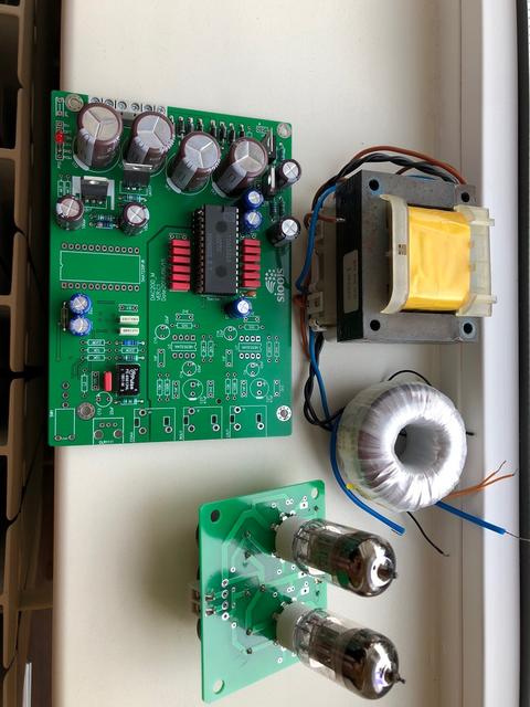
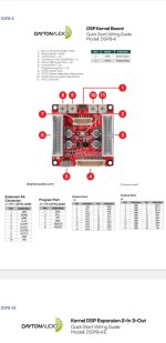
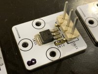
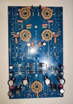
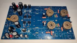
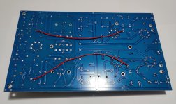
For sale are two Soekris dam1021 dac modules. One modules is brand new and one is slightly used. To the used one, the VREF mod that Soeren recommends was applied.

The brand new module is the dam1021-12: 0.012% resistor version,
it was purchased in February 2016 directly from Soekris (still have the invoice).

The slightly used module is the dam1021-02: 0.02% resistor version,
it was purchased in June 2015 directly from Soekris (still have the invoice).

For the brand new module I want 300 Euro,
I'm also willing to trade, please look below (I paid 341 Euro with VAT and shipping)

For the slightly used module I want 200 Euro,
I'm also willing to trade, please look below (I paid 267 Euro with VAT and shipping)

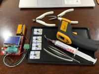
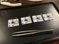
Included with each dam1021 board is the standard set (all brand new) of connectors that Soekris is delivering with each module


I also have a lot of brand new Nichicon FP caps, to upgrade the modules.
If you are interested, I will sell them to you for the current mouser price.
The following values are in m stock
1500µF/6.3V - 820µF/6.3V - 690µF/6.3V - 470µF/6.3V


I’m also willing to trade for one or more of the following items:
(Of course, I will pay difference in value)

Manufacturer sealed bags of:
2SJ74-BL
2SK170-GR
2SJ74-GR
2SK370-BL
And maybe other rare signal JFETS or dual JFETS

BurrBrown PCM1704-K DAC chips

Analog Devices MAT02 and MAT03 dual monolithic transistors

2 x Starkrimson® Ultra Amp Module

XRK Audio RTR TPA3255 Reference Class D amplifier

Please also take a look at my other offers in the Swap Meet


Here are some different shipping rates:
They may differ a little from country to country, for a exact quote for your country please ask.
Of course, I will charge only the prices I will have to pay)

Small DHL package worldwide (up to 2KG):
Without insurance and tracking: 10.99 Euro
With insurance up to 50 Euro and tracking: 14.99 Euro
With insurance up to 500 Euro and tracking: 47.99 Euro (DHL insanely raised the prices, this package is also up to 5KG)

Small DHL package within Europe (up to 2KG):
Without insurance and tracking: 5.99 Euro
With insurance up to 50 Euro and tracking: 8.49 Euro
With insurance up to 50 Euro and tracking: 13.99 Euro

Shipping within Germany will be cheaper, please ask.

I will ship anywhere in the world. Shipping costs strongly depend on the shipping method you prefer. Of course, I will only charge the real costs, I won't charge anything for packing materials and effort. I prefer to use Deutsche Post/DHL, but you can decide which shipper and which shipping method (letter, registered letter, small package, normal package, insurance, tracking) I should use.

As payment method I prefer PayPal for friends and family, so no extra fees will be added. Of course personal collection of modules in Cologne (Germany) and payment in cash is also possible.

Kind Regards

Phil

IMG_1008.JPEGIMG_1010.JPEGIMG_1012.JPEGIMG_1017.JPEGIMG_1018.JPEGIMG_1019.JPEGIMG_1023.JPEG
The

For Sale LaVoce DF10.10L CD + Eminence WG10

Grabbed these for a project very recently to see if I'd like horns in my space. Turns out I didn't really care for horn and CD. I also have some Eminence WG10's that make for a very good combo.

CD's were picked up just a few weeks ago but I lost some of the manufacturer packaging so I can't return them. Pretty much pristine condition otherwise. I have the box for one but lost the box for the other.

I can do $60 shipped for the CD's or $100 shipped for the CD+Waveguides within the U.S.

PM me for paypal.

20240119_115202.jpg


20240119_115238.jpg


20240119_115145.jpg

For Sale Iron Pre SE

I have Iron pre se to sell because I decided to build balance version.

450usd+ shipping(100usd for USA,120usd for most of Europe depending on country)

30VA 18V secondly 0-115v-230v
Chinese rcore trafo in iron case
Schaffner
Vilab rn55 23stepped attenuator
Chercroft zfoil 330R
Cmf55
Nichicon gold tune
DIY manganin resistor 100r for offset
(0mv-0.1mv)
Mogami solid core cable
RCA - Tellurium copper x1 , Mogami x1
Gold plated RCA jack x4
https://shop.oyaide.com/products/p-3071.html


Login to view embedded media

Attachments

  • PXL_20231221_075616286.jpg
    PXL_20231221_075616286.jpg
    576.8 KB · Views: 166
  • PXL_20231221_075634053.jpg
    PXL_20231221_075634053.jpg
    347.3 KB · Views: 157
  • PXL_20231221_075654031.jpg
    PXL_20231221_075654031.jpg
    457.9 KB · Views: 150
  • PXL_20231221_075634053.jpg
    PXL_20231221_075634053.jpg
    347.3 KB · Views: 142
  • PXL_20231221_075605321.jpg
    PXL_20231221_075605321.jpg
    536.4 KB · Views: 157

For Sale Nearly Complete RMI-FC100 Kit

SOLD

Hi all,
I have a nearly complete FC100 Kit for sale. When the FC100 thread first started, I followed it closely and purchased all of the parts (PCB's, several sample ThermalTraks for future matching, matched inputs (J1 & J2), most the rest of the caps, resistors, components, heatsinks, toroidal transformers - basically everything but the enclosure and a couple of the other matched transistor sets. For the longest time I held out hope that I would get to complete the build, but, alas, that phase of life has passed.

My offer consists of the following items:
  • 2x FC100 Boards
  • 2x front end power supply Boards
  • 2x toroidal transformers
  • 2x large heatsinks
  • 1x mini board for measuring ThermalTraks for matching purposes
  • several sets of ThermalTrak transistors
  • almost all of the components, most of which are labeled and in their packaging
  • to the best of my knowledge the only missing components were a couple of the matched transistors, but I can't guarantee

I've tried to post some pictures below, but please let me know if you want to see more. There's also a lot of paperwork that I can include: diagrams, invoices, BOM's, etc. I don't know exactly what I paid for all these components but i think it was over $500. I'm not sure what a fair price would be, but I would sell the complete kit for $200 plus shipping. I'll consider offers, and separating the toroidal transformers, since shipping those might get pricey. Obviously, a local pickup would be preferable - I'm in North/Central Virginia, USA (22701).

I regret not having the opportunity to hear this design in action, but I would be happy knowing someone else could put the parts I collected to use.

20240115_131646_resized.jpg


20240115_080819_resized.jpg

20240115_131129_resized.jpg

20240115_130744_resized.jpg
20240115_131003_resized.jpg
20240115_131147_resized.jpg
20240115_091243_resized.jpg
20240115_091232_resized.jpg

Ted

Attachments

  • 20240115_091243_resized.jpg
    20240115_091243_resized.jpg
    483.3 KB · Views: 83

PHONIC 740 mixer-amplifier

Is it someone that have experience with this?
This is faulty,SMPS is burned,blown IGPT,FUSE.
Owner said that this had another service attempt but SMPS burned again immediately.

Attachments

  • IMG_20230831_193943.jpg
    IMG_20230831_193943.jpg
    621.8 KB · Views: 445
  • IMG_20230831_194011.jpg
    IMG_20230831_194011.jpg
    479 KB · Views: 405
  • IMG_20230831_194035.jpg
    IMG_20230831_194035.jpg
    581.9 KB · Views: 336
  • IMG_20230831_194050.jpg
    IMG_20230831_194050.jpg
    605.8 KB · Views: 389
  • IMG_20230831_193928.jpg
    IMG_20230831_193928.jpg
    512.2 KB · Views: 339
  • phonic_powerpod_740deluxe 1.pdf
    phonic_powerpod_740deluxe 1.pdf
    6.5 MB · Views: 600

Values of air core inductors?

Is there any way to tell what the values of these air core inductors are? This is the crossover for a Vienna Acoustics Maestro center speaker.

I am planning on swapping out the tweeter, (which sounds harsh), and replacing with a ScanSpeak Classic to match my main speakers.

It is odd...the original versions of the Maestro came with that ScanSpeak tweeter. This version seems to have a much cheaper tweeter (I picked it up secondhand off Ebay a few years ago). This tweeter has the same impedance as the ScanSpeaktho, so I think I can start simple. I'd like to try a straight swap first, listen, and then adjust the crossover values once I understand what needs to be adjusted.

I plan to use my studio mic to capture the freq response.

I have a Fluke189 multimeter. Any way to run a test to find the mH values without desoldering?

Attachments

  • 20240116_213540.jpg
    20240116_213540.jpg
    477.4 KB · Views: 111

For Sale SP14 preamp board partially assembled

For sale a SP14 preamp board octal partially assembled.
Bought in 2018 but but never managed to finish completelly and now I am interested in other projects .
Price 125 Euro + postage.
I also have a Bendix 5852 aka 6X5GT,bought it specifically for SP14.It was sealed in a original box,I opened it, powered to see if it works and it did.
Price 150euro + postage.
I also have a NOS RCA JAN CRC-6X5GT bought from Tube Museum New York,price 30Euro+postage.

Sold.​

Attachments

  • IMG_20240119_151654.jpg
    IMG_20240119_151654.jpg
    475.2 KB · Views: 108
  • IMG_20240119_151732.jpg
    IMG_20240119_151732.jpg
    359.1 KB · Views: 105
  • IMG_20240119_151818.jpg
    IMG_20240119_151818.jpg
    287 KB · Views: 93
  • IMG_20240119_154230.jpg
    IMG_20240119_154230.jpg
    413.2 KB · Views: 85
  • IMG_20240119_154817.jpg
    IMG_20240119_154817.jpg
    253.5 KB · Views: 91

For Sale AJX Kit

I want to sell my partly finished AJ-X, as I don’t find the time to build a suitable case.

The boards are fully assembled, mounted on heatsinks and tested.
All transistors are matched and only high quality parts are used (PRPs, mills …).
Heatsink dimensions: 40x20x8,5cm

Price: 550€ + shipping

DSC_3509.JPG

DSC_3512.JPG

DSC_3513.JPG
Optionally I can offer transformers (2x18V, 500VA, shielded), parts for PSU (Capacitors: 33000µF/50V) and additional stuff (see picture).
(for dual mono setup)

Price 220€ + shipping

DSC_3522.JPG

DSC_3524.JPG

Remark: with some minor modifications, it is possible to build 4 AJ (mono) amps instead of the 2 AJX (mono) amps.

Local pickup in Salzburg, Austria or shipping

datasheet wanted: NEC AC06DGT

Ok, I put it here because this is not for audio. But I'm trying to get an old camera working again. First step is getting to understand the electronics and so far I have been able to trace the pcb (good thing is was only double sided) and find almost all the components. But a single component so far is missing.

Does anybody has a datasheet for a NEC AC06DGT? This is a part in a TO-66 (*) package, which looks like a small TO-03. I did find some references to NEC ACxxxx parts and those are thyristors. But I'd like to be sure about this.

(*) or TO-123 or TO-124 or TO-213 depending on thickness of the base

For Sale Some SANYO / FAIRCHILD NOS transistors for sale

I have for sale some SANYO / FAIRCHILD NOS transistors for audio.

The goods will be shipped in a cardboard box , transistors will be packed in antistatic bags. Ship from Poland.

Payment: PAY PAL , wire transfer

I don't send to RUSSIA , IRAN , SYRIA , IRAQ , LIBIA , VENEZUELA , NORTH KOREA

Shipping to EUROPE ( including ISRAEL & CYPRUS ) - registered priority mail - 5 EURO

Shipping to NORTH AMERICA (registered priority mail ) 6,5 USD

Rest of the WORLD ( registered priority mail ) 10 USD

Prices in EURO / USD


1) KSA1381-E i have 150 pcs.
PNP , mfg - ON SEMI , hFE 100 - 200 , package TO220 isolated
MOQ = 25 pcs. or more

KSA1381-E x 25pcs. = 10,04 euro ( 0,40 euro / 1pc. )
KSA1381-E x 25pcs. = 10,71 usd ( 0,428 usd / 1pc )

Complement to 2SC3503-E ( KSC3503-E - obsolete part )

2) 2SC3503- E i have 325 pcs
NPN , mfg - SANYO ,hFE 100 - 200 , package TO126 ,
MOQ = 25pcs or more

2SC3503-E x 25 pcs. = 12,50 euro ( 1pc = 0,5 euro )
2SC3503-E x 25 pcs. = 14,25USD ( 1pc = 0,57 usd )

3) 2SC3382- S + 2SA1391-S i have 300 pcs + 300 pcs
NPN / PNP low noise ( 50V / 200mA ) ,hFE 140 -280 ,mfg SANYO , package; TO92 ,
MOQ = 50pcs. 2SC3382-S + 50 pcs. 2SA1391-S or more

2SC3382-S / 2SA1391-S ( 50pcs + 50 pcs.) = 21,00 euro
2SC3382-S / 2SA1391-S ( 50pcs + 50 pcs ) = 23,50 usd


Below original photos + datasheet

Attachments

  • 2SC3503E.jpg
    2SC3503E.jpg
    97.5 KB · Views: 160
  • 2SC3382 2SA1391 małe.jpg
    2SC3382 2SA1391 małe.jpg
    97.5 KB · Views: 165
  • 2SC3382.pdf
    2SC3382.pdf
    74.8 KB · Views: 87
  • KSA1381 D małe.jpg
    KSA1381 D małe.jpg
    100.9 KB · Views: 107
  • KSA1381.pdf
    KSA1381.pdf
    208.3 KB · Views: 1,159
  • 2SC3503.pdf
    2SC3503.pdf
    51.2 KB · Views: 56

various ECC82

hello-
i have a few tested ecc82 for sale.
i can post pics if wanted but for now i only add the quick test reports made on utracer6, fillament is powered by rigol dp832a, set to deliver exactly 300ma current.
test is set up as per datasheet, typical values.
20240120_122158.jpg

Attachments

various ecc81 phillips telefunken

hello-
i have a few tested ecc81 for sale.
i can post pics if wanted but for now i only add the quick test reports made on utracer6, fillament is powered by rigol dp832a, set to deliver exactly 300ma current.
test is set up as per datasheet, typical values

Attachments

Hifonics Zeus ZXi 1501 - defective output transistors, musitech, MAP 6808, no datasheet

The output transistors had low R-values, short when powering up, desoldered the ones that were bad and the amp powered up normally.

I couldn´t find the datasheet on the web, https://www.jotrin.com/product/parts/MAP6808, I asked jotrin via e-mail and they don´t have it.

https://www.made-in-china.com/showroom/musitech/

Musitech themselves aren´t better either, I found at least someone with their name on the internet, but they only have a phone number after the resgistration, I will try to inquire over the website, maybe in the meantime anybody knows this transistor, or can navigate the web better than me.

thank you all in advance.

How might a 6GM5 do tied as triode?

got a lot of 12 6GM5 to sell and trying to think of ways to promote its use.

- know it can be used push pull :

Hi quality Push Pull Amplifier with PL500 / PL504/ EL500 / EL504 / 6GB5 /6P41S /27GW6 and 12AU7 /ECC82 and 12AX7 / ECC83 | TUBES.RS – Tube Amplifiers & NOS Tubes

https://i.imgur.com/A7uB7fS.jpg

https://i.imgur.com/eHTgtr9.jpg

- - how it might fare in SE or PP triode amplifier use? or perhaps regulator pass element?

GPIO control in piCorePlayer

I am migrating from moOde to piCorePlayer. in moOde I had scripts to control a fan based on cpu temperature and a 12v trigger to turn on my amp.
I am a novice as far as programing goes. I made the scripts for moOde by cobling together different tutorials and forum posts. I can't find anything similar for piCorePlayer.

I need:
GPIO12 to be a pwm signal to control the fan

GPIO16 to go high when playback starts, and go low 120 seconds after playback stops.

I used the proportional version of this for fan control:
https://www.the-diy-life.com/connecting-a-pwm-fan-to-a-raspberry-pi/

And this is what I did for the 12v trigger:

enter:
nano /home/pi/autoamp

paste:
#!/bin/bash

# This Script is to read the Alsa Sound State and Automatcally
# swing a GPIO pin to allow auto switch on / off of an external
# amplifier, its crude dirty and badly written any sugestions
# or criticism welcome
#
# Trevor Cockayne trevoml@gmail.com


# Exports pin to userspace
echo "16" > /sys/class/gpio/export

# Sets pin 16 as an output
echo "out" > /sys/class/gpio/gpio16/direction


count=0

time=120

let count=$time

for (( ; ; ))
do
if grep -q "closed" /proc/asound/card1/pcm0p/sub0/hw_params; then
# echo "DAC IDLE"
let "count++"
else
# echo "DAC Playing"
count=0
fi
if [[ $count -gt $time || $count == $time ]]
then
# echo "Amp Off"
echo "0" > /sys/class/gpio/gpio16/value
count=$time
else
# echo "Amp ON"
echo "1" > /sys/class/gpio/gpio16/value
fi
# echo $count
sleep 1
done

enter:
chmod 755 /home/pi/autoamp

enter:
nano /etc/systemd/system/autoamp.service

add:
[Unit]
Discription=Automatic Amplifier Control
[Service]
ExecStart=/home/pi/autoamp
[Install]
WantedBy=multi-user.target

enter:
systemctl enable autoamp.service

enter:
systemctl start autoamp.service

Will these work for piCorePlayer?

Thanks,
freebirb

Pumpkin Preamp Kit (from ZenMod)

Like the offered AJX, I want so sell my partly finished pumpkin preamp, as I don’t find the time to build a suitable case.

The boards are fully assembled and tested.
All transistors are matched (by ZenMod 🙂 ) and only high quality parts are used.
Kit includes O-Core transformer, XLR Sockets (5x In und 1xOut, more available) and additional stuff (see picture), but I would also sell just the assembled boards, if preferred.


Price: 350€ + shipping

I can also offer a set of blank boards (pre + shunty).

Local pickup in Salzburg, Austria or shipping

DSC_3516.JPG

DSC_3517.JPG

DSC_3519.JPG

DSC_3518.JPG

LOMC Load Values

I want to build the OddWatt Riaa Phonograph Preamplifier Groovewatt.
I have some "unknowns" in the schematic.
No experience with MC cardridges, but I want to build it to be ready.
In het schematics, there are 4 resistors, which can be added to change the load value. (RED)
1705603984250.png


Second, what is the MC jumper which add 100pF used for ? When do I need this ?


Kind regards,

Attachments

  • 1705603883012.png
    1705603883012.png
    62.4 KB · Views: 79

Arduino Audio Watt Meter

It has been a while since I posted on the forum. I fell in love with another hobby and although I enjoyed my audio system, I didn't do much with my test gear. I wanted to buy a bench meter that could display audio Watts. Most have a math dB or dBm function, but the references usually only go to 50 Ohms. There are a few that do measure at 4/8/16 Ohms, but they were not in my price range. So I decided to build my own using an Arduino. I'm not much of a coder, but I did fall in love with the Arduino because of the amount of information (books, kits, forums, etc.). So here is my project in it's finished form. Due to the 4 line display having such a large circuit board, the final enclosure is a bit larger than I prefer. I did find an OLED display that has a large display and small board footprint. So there will be another revision forth coming!

The small 2 line display under the finished 4 line completed unit is my single channel prototype. I created my own circuit board and then populated myself. The fab house had some minimums, so I just had the board made. The magic of the circuit is the LTC1968 RMS to DC converter. Unfortunately, the max input voltage is 1V AC. Therefore, reducing the input requires quite a ratio. I buffer the output with a simple gain of 5 buffer to give my ADC full range. There are some other minor tricks in there, but not much else. I could have added another unity gain stage, but it didn't improve the performance. The most important thing in all of this was to have my bench meter calibrated. It was only a few years, but I sent it out for official calibration. There is absolutely no way to build and calibrate this without an accurate meter. For the final unit, I have a SS amp on the bench and I'm measuring both channels under load.

Below are some pics. The board on the bench and the displays show how accurate the circuit can be. Don't mind the decimal point on the measurement; I was messing around with the scale in the software. I can measure against 8/4/2 Ohm loads, there is a mode to measure in single channel only and then you push-hold the buttons for other modes.

20240117_170817.jpg


20240117_170745.jpg


20240117_165218.jpg


20240117_170000.jpg


20240117_165355.jpg


20240117_165659.jpg


20240117_165740.jpg
  • Like
Reactions: stv and HeyBill

Can we combine the advantages of line- and point-source technology into one speaker?

Can we combine the advantages of line- and point-source technology into one speaker?

I'm now inspired by vintage ADS L2030 speakers. They're described as being designed to combine the benefits of both line- and point-source technology in a single speaker. They use four midrange drivers and have a midrange toggle switch for switching between line-source and point-source operation.

According to the brochure, the main bigger midrange is more efficient than the remaining three smaller midranges. In point-source mode, only the main bigger midrange sings, whereas, in line-source mode, the four midranges sing concurrently. The line-source mode is advertised as "weighted line-source", which is also promoted as combining the advantages of both line-source and point-source technologies.

However, these speakers were produced in the early 1980s. I have never heard the sound of these speakers, though.

I'm curious whether this idea should be revived in modern design. I'd like to hear other people's thoughts.
  • Like
Reactions: head_unit

Thanks before I move on over.....for a time.

Hey and Hi to all of the Audiopliles here who made my life much easier, with some vintage Hi-Fi amp circuits and questions that I had concerning things that were driving me crazy for a time. There are too many names to repeat, but you probably remember the dimwatt who asked those questions and struggled to understand some for a time. I am going to be posting a little on the musical instrument side of the forum and will hopefully be welcomed and tutored like I have been here. I have completed my first really challenging project with your advice and great experience based know how, and I am quite happy with the results. One Can take a vintage tube Hi-Fi and with the proper Science, a little cash for parts, and patience turn it into a fine, although basic guitar amplifier. I wish that I knew how or even if it is possible, to let you here it in action, although you might not like the musical "talent" behind it all. I doubt very seriously that Mr. McGohan would recognize his creation now, but wherever he is, I thank him as well for turning out such fine work back in the early "60's.
Don't get me wrong, I am sure to be back here as I am going to continue to pick up bargain's, like the McGohans, Harmon Kardons, Layfayettes, and Marantz' amplifiers that I already have purchased to experiment with, and perhaps make useful again. They are so much more reasonably priced than the usual guitar amps. If a guitar amp has tubes in it, the seller usually think it's worth a mint. I know that I will need some ,more advice here though. I realize that to the experts Here, a circuit is a circuit in a major way. However, when all you have ever tinkered with before had names like Fender, Gibson, and Vox on them, it is like a whole new world is opened up with vintage Hi-Fi. I can see the similarities to be sure, but there are many "head scratchers" as well for one who picks a moniker like dimwatt. I hope that sometime in the future, I too can be of service to someone in need of advice here, and be able to give them the benefit, that in my opinion, has been like conferring with the contributors to the Radiotron Designer's Handbook. Thanks !
Projects by fanatics, for fanatics
Get answers and advice for everyone wanting to learn the art of audio.
Join the Community
507,646
Members
7,882,617
Messages

Filter

Forum Statistics

Threads
405,961
Messages
7,882,617
Members
507,646
Latest member
joveaaron