• Locked
EV charging insulation transformer problem

it is out of audio topic but maybe some electrician expert can help me.
I live on Germany here we have 3 phase power star with center neutral to ground,each phase to neutral 230v and phase to phase 400v. max allowed current per phase 20A
unfortunately I have an electric car that can charge 7kw 230v 32A monophase no 3 phase
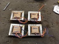
I could slavage 2 toroidal transformer 230v 230v 7kVA from solar inverter.
so I wired primaries in series connected to phase 1 and pase 2 they receive 400v, 200v each primary up to 20A
secondaries are in parallel they provide 200v up to 40A
electric car charges fine up to 24A but more than. that it stops because the voltage gore below 190v (sag from cables and toroids)
I am fine with that and at 24A all works fine.
To avoid the undervoltage cut off I added a third transformer at the secondaries of the 2 big toroids to increase the voltage from 200 to 220v
it is a 1KVA EI transformer 230v 24v 40A connected as autotransformer.
I get 220v the car charges up to 20A but if I increase the amps then the loading cable device (the one that tells to the car ar what amps it has to charge) makes a reset, screen goes dark and more strangely after a few seconds the 20A circuit braker at the primary (400v) side, trips. I reproduced this 3 times.
I suppose that maybe the loading cable device RCD senses a loss to ground, my EI transformer was lying on moist soil, I could understand a reset of three charging device
but why is the circuit brakes tripping?

hos is it possible that more than 20A are flowing for an instant? peak overcurrent?

Deaf Bonce Apocalypse AAP-1600.1D unknown component values

Good day bros. I hope every body are well and good. It's my first time repairing a Deaf Bones car amp and did not expect that they replaced the part numbers of all the important components of the amplifier. As I found out after troubleshooting 2 output FETS are shorted I believe the chip drivers are gone too which caused the clipping problem upon power on. Can anybody please tell me the exact component part numbers of the output FETs (labeled B1) ,supply FETs (labeled H1) and the drive chip (labeled C5) which are all shown circled in white in my photos. It would be a big help to me because some Deaf Bones dealer pop out in my place lately and a lot now are in the market. Your response are very much appreciated. Thank you very much.
More power and good health to all.

Attachments

  • Deaf Bonce 1600.1D 1.jpg
    Deaf Bonce 1600.1D 1.jpg
    143.6 KB · Views: 436
  • Deaf Bonce 1600.1D 2.jpg
    Deaf Bonce 1600.1D 2.jpg
    237 KB · Views: 422
  • Deaf Bonce 1600.1D 3.jpg
    Deaf Bonce 1600.1D 3.jpg
    217.5 KB · Views: 405
  • Deaf Bonce 1600.1D.jpg
    Deaf Bonce 1600.1D.jpg
    278.8 KB · Views: 490

Constant Clicking Sound Sangaku DIY

I recently built a Sangaku and whenever I plug headphones into the 1/4 jack there is a persistent clicking sound. It's reminiscent of a chain moving through a gear, I've attached a video below. (it's very quiet, you may need to turn the volume up quite a bit.) This is most prominent on my Beyer T5p, although it's almost as present on my Beyer T70 (the 250 ohm version), Sennheiser HD800s, and less so on the Hifiman HE400i. It's basically nonexistent on the SJY Moonlight or HIfiman HE6se (not surprisingly). I'm not sure where I could have gone wrong here. The only thing I'm missing right now is the 3 switches for the front and the front and rear panels. I used a bit of cable to connect everything in the place of that. Any ideas what could be causing this?
Source is a Ayre Acoustics Codex and I already checked that.
1708129836162.png
1708129870512.png
1708129918801.png

Speaker for Single Side Band (SSB) of ham radio

Greetings all,

Listening to the SSB voice on ham radio may be an unpleasant experience due to the speakers used (small, inefficient), their mounting (up or side firing), amplifiers with higher (10%) distortion, and the like, even in better transceivers. Although most transceiver include phone output, I do not like using phones for various reasons. Interestingly, some of the new higher tier - and price transceivers now include option to add (multiple) speakers with a rathr sophisticated processing.

That made me start to think about adding external speakers.

The SSB audio bandwidth is about 300 Hz to 3300 Hz, but adjustable filters are used to (usually) narrow the bandwidth, but sometimes the filters are used to shift the lower and/or higher edge, e.g. to avoid close signal. Thus the speaker should cover the bandwidth from 250 Hz to 3600 Hz with excellent intelligibility.

The speakers should have high efficiency so that a battery operated, and such small and low noise amplifier, could be used.

Although I do not think that a low distortion would be difficult to achieve, for the sake of completeness, I am adding this requirement so that the already distorted signal by, e.g., narrow filter settings, noise, etc. is not degraded further.

I was initially contemplating a single-driver speaker, but then I though that I will also be using the speakers for casual music or speech listening, so perhaps a two-way would be better choice. I was contemplated a wave-guide loaded tweeter (higher efficiency, better focus), either off-the shelf or using one aguerpro’s wave-guides from the "Open source Waveguides for CNC & 3D printing!" thread, mated to a low distortion mid-range/woofer.

So, if you could point me to some designs/kits, I would appreciate it.

Kindest regards,

M

Power Supply Caps? or Output Caps?

I've got this Quadraflex Reference 450R receiver and I would like to replace the power supply capacitors. There are no schematics for it anywhere online or in print form so I'm hoping someone can say for certain if the two large black capacitors near the output transistors are for the output stage or the power supply. They are marked 6800uF 50V.

Please see the following photos. The third photo is of the Power Supply Board.

1.JPG


2.JPG


Power Supply Board...

3.JPG

Laminations for OT

Hi all,

I've been winding a few custom output transformers using M6, Z11 (and some unknown laminates in the junkbox) for guitar amps with surprisingly good results. I once got this advice from Sensei Ingo:

Lamination: The old Marshall Transformers used the British steel named "Vicor", a semi processed steel. This "Quality" is obsolete and isn´t available any longer. So what to do. For good results for a first project just look for the semi processed steel 660-50.

I have tried to found out what Ingo referred to but failed so far. Does anyone know what "semi processed steel 660-50" is and where to source it, or perhaps something that is similar?

My next project is an EL84 based 18W "Plexi". I would like to use this laminate and find out if it's the unicorn blood I've been looking for so long...

Thanks in advance!

/Mike

REL Quake replacement board suggestions?

Someone asked me to fix a Quake but the bridge and fuse area of the board was so badly burned out. I've tried to get it working but it sounds like DC leaking. The sub vibrates with a loud hum where the cone is moving so rapidly.

I'd like to fix it, I replaced the mosfets, and bridge diodes etc but was wondering if anyone with more knowledge than myself could help me find a replacement board to stick in there.
20240219_233324.jpg


20240219_232718.jpg

Attachments

  • 20240219_232718.jpg
    20240219_232718.jpg
    240.6 KB · Views: 82

Rounded Triangular Prism Speakers?

After developing some limited skills in bending wood with the Tasmanian Devil home streamer, I'd like to try next a pair of large bookshelf/small standmounts using bent wood.

This time I'd like to try a rounded triangular prism design which I find just as visually appealing as the rounded rectangle of the home streamer. Speakers in my experience spend a lot of time not being used so it's helpful if they look nice even while asleep. Curves I find relaxing but seem to be rarely used in the commercial world, possibly because of cost/difficulty of construction? As I'm already finding with the home streamer, curves also seem to help rather than hinder good sound. The triangular design has only front and rear on the same plane, bottom and sides are on 3 different planes. Dave has mentioned several times on the forum that BR shape is not important, only volume, so I hope that applies here. This would be a rear-ported design unless anyone has other thoughts.

I've found a few triangular speakers online but they seem to be mainly small corner speakers or floorstanding pyramids. Has anyone tried building something like this? I have no test or measuring equipment other than my ears (and Mac-based simulation software is hard to find), so would like your help in deciding a) whether the shape is viable and if so b) which driver configuration and units to use.

They will be used in a 6m x 5m lounge and I'd like them on cylindrical stands (I'm thinking the tree trunk look!) for all types of music. Good sound stage needed, balanced performance across the spectrum, to be used with an integrated streaming amp such as the Wiiim amp or Bluesound Powernode. Since appearance and geometry is important, the drivers will need to look and work well in a triangular baffle. Colour scheme this time will be black, white and silver, so no gold drivers this time around. Probably an all-white exterior with black, white or silver drivers. Tweeter if used must be robust to prevent finger-poking, so no soft domes unless they have a front grill.

Attached are four ideas: FR, 2-way, 2-way with ribbon tweeter and small 3-way. Would love to hear you thoughts on which one to go with and what drivers to use. WAW or coax could also be an option if they could be made to fit into the shape. The geometry of the standard 2-way currently appeals (best match for the sloping sides) but I'm open to any of them. Driver budget is US$500-700 for the pair (including crossovers if needed). Could go higher for something special. Size can be anything from 12 to 24 inches tall to suit the chosen driver(s) although volume will be about half that of a rectangular box of the same height and footprint. But to me that's worth it to have something that will hopefully bring a smile to everyone who sees and listens to them.

Thanks all.

Attachments

  • Triangle 2 Way Ribbon.jpg
    Triangle 2 Way Ribbon.jpg
    24.7 KB · Views: 97
  • Triangle 2 Way.jpg
    Triangle 2 Way.jpg
    25.4 KB · Views: 98
  • Triangle 3 Way.jpg
    Triangle 3 Way.jpg
    26.7 KB · Views: 87
  • Triangle FR.jpg
    Triangle FR.jpg
    24 KB · Views: 95

Amplifier with continuous change between SE and PP operation

Dear all,

I know the basics: a SE OPT amplifier needs a gap to avoid core saturation, the PP avoids the (big) gap as DC currents cancel out. Since I joined Diyaudio discussions regularly pop up about PP transformers being used with only one side driven, the other side being loaded by a CCS (a mosfet or a tube), this allows the SE sonic signature using PP OPTs (smaller, maybe available).

I can’t remember having seen an amplifier that allows (gradual) transition between PP and SE, preferably keeping the gain constant. I saw/have some ideas, like feeding a balanced PP amplifier with an input transformer loaded by a potentiometer, with the wiper connected to ground. In the middle position both legs get the same signal, the amp is PP. Turning the pot, each leg becomes a different signal, something between PP and SE. With the wiper at the extreme of the pot, the amp operates in a sort of SE (but take care that this one leg is not clipping because it now gets twice the signal as in PP operation). But say the amp uses triode output tubes, in the SE case one may not be amplifying, it is however still loading the transformer with its low plate impedance. Good or bad?

Please share existing projects, your ideas or schematics. Given the circuit is doable I am willing to build a prototype, I have input transformers (LL1540), OPTs, lots of different driver and output tubes, not afraid of using mosfets (enhancement and depletion), have multiple adjustable PS that can all be used for testing.

The purpose of this exercise is to have an amplifier that can play multiple distortion signatures by turning pots or maybe some switches, so the influence of variables as PS, employed output tubes, OPTs, being warmed up or not are kept to a minimum. Constant gain would be nice as I plan to use this for the midrange in a bi-amplified system, and because differences in gain can also be perceived as differences in SQ.

Many thanks for your ideas!
Erik

Solved TDA7293 blowing up

Hi guys and gals, liftime of electronics, found the tda7293,4, exploding caused by stanby and mute, chip manufacturing was changed but datasheet no longer relecrs the changes. The MAX voltages used to be the v+ but now causes the chip to explode, limit the stanby and mute voltage to 5 volts eather with zener diode or resistor devider, before the rc network described, also do not connect 2 chips mute or stanby together as if one chip fails both chips will blow.

Community Suggestion

Hello community from Germany.

I'm new to the forum and I can say that I'm ignorant in terms of calculation, development and especially the subtleties of a quality enclosure, but luckily I'm good at implementing it. In the last month I've spent a lot of time going through the forum and especially the FR part of it, looking for information related to a combo FR driver - enclosure for the listening room. Unfortunately, I am totally overwhelmed by the multitude of right combinations, for which I appeal to the well-known kindness of the community of this forum. I would like you to recommend me a combo driver - enclosure for a 30 square meter room which is already fairly neutral acoustically. Favorite music is Jazz and slow blues 90% the rest classical and others,low to medium listening level.For size it can reach up to medium (up to 1.2m high). As it is discussed heatedly and he knows that there is no perfection in measurements, so I will not want something like that, I want him to sing naturally as pleasantly as possible for connoisseurs. I am open to any proposal from you.
Thank you in advance for your support.
Alex

GW-8004 Open Baffle Testing (Understanding Results)

Hi all,

I picked up some GW-8004 coaxial full range drivers, they have a built in crossover. I picked them up because they have high Qts and seem to have quite a bit of excursion travel potential. This is the driver:

https://www.parts-express.com/Goldwood-GW-8004-8-8-Coaxial-Speaker-290-378?quantity=1

20240215_164944.jpg


Here's the manufacturer graph response:

1708275437828.png


Here's the manufacturer T&S:

1708275463957.png


I went ahead and measured it myself on DATS V3. All 4 drivers measured very similar to this:

20240215_170218.jpg


GW-8004_Driver01_DATS.jpg


Here's a near field (3" non-anechoic) no baffle measurement (driver suspended in the air more than 3 feet away from surfaces, etc). I didn't gate or anything just to see a general idea of what it was doing. Mostly looking at that 3~6khz dip. The roll off is expected under 1khz I think here. And the rest was ok.

GW-8004 Free Air No Baffle Near FIeld Response.jpg


I used Basta to look at potential baffle sizes. After playing in that and doing some calculations for baffle width and all, I realized, it won't matter because I'll never make this large enough to support really low frequencies. I potentially would like to get down to 100~120hz with these after EQ with some boundary gain (they will mount near walls all the time). But I calculated a rather large 3.4m baffle to do that. Obviously impractical. And so the differences from 24 inches and smaller didn't seem to matter. So I figured, I'd just measure it and see what I could do.

I made a few baffles that were around the sizes I wanted to work within and made some temporary wings to extend the baffle while reducing the front baffle width here and there.

I started with 12" x 18" baffle with and without 3" wings on the sides.

20240218_100947.jpg


Here's a few measurements. These are just near field but non-anechoic, I know they're not accurate, just looking at the overall shape of the response based on the baffle which should show up ok with fairly near field. The black line is no wings, so the baffle width for bass is 12" x 18". The other lines are two different position measurements with 3" wings ont he sides and they were more consistent but it was clear the extra baffle width helped lift the bass under 400hz.

GW-8004 Baffle 12 x 18 with and without Wings Response.jpg


Next, I wanted to shrink the front baffle some so I reduced to 10" x 15" and kept the 3" wings.

20240218_110210.jpg


20240218_110422.jpg


I later added some cut out notches around the tweeter to see if it would matter. I know this is a practice to explore with tweeter + woofer two-ways, but I didn't know if it would help with a coaxial driver like this. I don't think it matters at all, so I likely will leave the notch out in the final version. Overall I think the 10" x 15" with 3" wings (16" baffle width, by 15" height, for bass) still seems to keep enough bass for this purpose near a boundary (walls, ceiling, floor, etc). I know it will have different response from a vast distance. I will measure that soon. For now, just trying to get quick measurements just to see the baffle width changes and the bass response.

Blue line is no notch.
Black line is with a notch centered around the tweeter the size of the tweeter diameter.
It didn't seem to matter much. It maybe took down some output from the mids and treble by 1db to 2db or so here and there, but it also lost 1~2db in bass.

GW-8004 Baffle 10 x 15 with Wings and Notch or No Notch Response.jpg


=================================================================

So, some comments and questions for anyone willing to help out:

1 - These are going to be used as surrounds so they will not get a lot of primary use. I mainly am looking at getting 100~120hz to 15~16khz bandwidth from them. They don't have to be flat and I'm going to EQ some. I plan on increasing the low frequency a bit with boosting and maybe some cutting on the 1~2khz range mids and a bit at 7~14khz treble ranges a little, but not a lot. That's just for context of use. It's going to be mostly ambient stuff, effects, rarely ever going to be voice or instruments and will not be the primary source when listening. Again, these will be surrounds, just for context.

2 - I'm trying to figure out what I can do about that 3~6khz null. It's the driver. You can see in the free air measurement and on different baffles, it doesn't change or move. I measured a 2nd driver to compare and it has a similar one but its shifted to different frequencies a bit. I imagine this is just a constant I will have to live with, with these drivers. Some sort of cone break up or interference between the tweeter and woofer? Any help on what this is really and if there's anything that can be done with it (I doubt it)?

3 - Any suggestions on baffle sizes and/or the wings or notches? I don't think the notches matter here since the tweeter is in a coaxial. But I'm open to any suggestions. Ultimately I'm going for a slim depth on these as they will be near walls, so figure they will pick up some boundary gain a bit. I'll measure that soon after getting the baffle width ironed out. Any suggestions on 10" and 3~4" wings? They probably will end up in a U shape, as I think doing angled wings will be a bit beyond my craftsmanship abilities on long panels. I can do that with a miter on studs and stuff, but I don't have anything to do that on long panels.

After some more tinkering, I'll do a rough baffle and wings build with plywood and do some on-wall measurements after figuring out, with any help here, any changes to the baffle.

Thanks 🙂

Very best,

My uTracer 3+

In the process of making my uTracer3+ (400V), tube curve tracer from https://www.dos4ever.com/uTracer3/uTracer3_pag0.html

I ordered the processor with program from Ronald at dos4ever.com, and as a true diyer made my own version of the PCB. I added all the mods to the original 3+, and added FDTI cable USB connector and two extra sections for the Grid Loupe and the Capacitor forming options.

I have also the extra higher heater current bulk converter from Albert Valiente and Voltage Volt/current meter options. I bought the bulk converter PCB and meter from Aliexpress, and made my own pcb for the HR supply using Albert design.

Albert mods, grid Loupe and Cap forming circuits can be found in the uTracer Lab Notebook PDF document.

More pictures will follow.

Attachments

  • PCB.jpg
    PCB.jpg
    283.7 KB · Views: 254
  • Like
Reactions: Captain B

Nakamichi Pa7 update info.

I have an original untouched Pa7 I bought new in ‘86. I am looking for info on updates that can make it better. I saw something about improving the bass in that there is evidently a roll off in the low end that can be improved pretty easily. Right now the amp sounds great and has no issues. I am just looking to make it as good as it can be.
All I have done is adjust bias and checked dc offset. I also replaced output binding posts with Cardas. Any help would be much appreciated.

SBAcoustics SB15 5x8?

Anyone have experience with they SBA SB15 5x8 woofer?

https://www.madisoundspeakerstore.c...ics-sb15sfcr39-4-5x8-paper-cone-woofer-4-ohm/

I am considering a narrow (e.g. appox 6-7" wide) tower 3 way, with an SBA tweeter at 4k, and the Scanspeak 10F for the mid down to around 300. The SB15 seems like a great option for the low end to fit nicely on the front panel, and 89db sensitive for the 4ohm version.

I love the long racktrack design. It reminds me of the Linn Keltiks I heard back in 1999. Those speakers still live in my memory.

That dip at 50hz tho. Is that something to be concerned about?

Bracing and stuffing in a small box

For my small sealed sub project, I settled on a sealed box design of 12"w x 18"h x12"d and a 10" driver from SB Acoustics. Approx 1ft3 /30l of internal volume. I am using as a passive design with an external amp.

I am using 3/4" baltic birch, and routering the ends of the panels to create notches on the side and top panels to maximize glue contact area, eliminate any gaps, and minimize the plywood edge exposed. I plan to add extra 1"x1"xL" blocks inside on all the edges for more panel glue contact to really make a strong seal and joint all the way around. I should have about 1.5in of glued wood along every edge.

For a small box, do I need to worry about extra bracing?

And, I see mixed opinions on adding damping materials on the inside walls/ stuffing in the box. Should I line the walls, add stuffing, or at this small size does it really even matter?

The low pass filter on my amp is set around 100Hz. This is really just for low end extension in my basement music/ 3.1HT setup. Low ceilings in my 1927 house, so I get decent room gain, and I small sub is all I need (and have room for).

20231228_193127.jpg

NAD L75 - Power-ON issue

Hi All

I have a NAD L75 small format surround receiver that I use as a 2-channel amplifier for my PC speaker setup.
It has developed an issue when powering on the unit. You can hear one of the relays clicking away multiple times but the amp does not immediately switch on. Sometimes after just a few relay 'clicks', sometimes many clicks that could last a minute or two, the unit does eventually power on and there are no operating issues from then on; everything seems to work fine. Often if you turn the unit off again and then back on it will turn on fine without issue. If it's left for a few days then it's highly likely to have the initial startup issue again. Recently this was also accompanied by some popping from the speakers while it was trying to power on so I'm not sure if this is a related issue or not. There is a second relay click a second or two after the unit powers on which I assume is the speaker protection circuit. Another possible clue is that the display when in standby mode [it just shows the time] is very dim and flickers on and off. Once the unit powers on, the display works as normal.

Below is a link to the service manual with schematics:
https://www.manualslib.com/manual/1422086/Nad-L75.html

I isolated the clicking relay at startup to the "AC Outlet PCB - KUP11431-2" RY91 - BSL1A008ZE - RELAY - SDT-S-112DMR and thought that may have been the issue so I replaced it which made no difference at all.

There are no obviously swollen caps that I can see, no burnt components etc. I'm assuming that the issue lies somewhere in the initial power supply boards before all the amplifier, decoder etc. but I'm a bit out of my depth as to what it could be. If anybody can assist and give me some direction on what the issue could be... I'm more than capable with a multi-meter, soldering iron etc. so fixing the issue shouldn't be too hard if we can work out what it is!

Thanks
Dave

RAAL 70-20xr and PTT6.5 Compact TL

Over in the PTT6.5 and RS28F TL thread, I was very impressed with the Purifi's midrange and bass abilities, so when I had the cabinets built I asked my cabinet maker to build a second set of baffles with a cutout for the RAAL 70-20xr ribbon tweeter. As I am waiting for the TL to get re-worked/re-built due to an improper seal in the internal channels I started to look at the RAAL 70-20xr as a pairing to pass the time by designing a XO. Since I don't have a back cabinet yet, I mounted everything open baffle figuring I will just work on the XO as it will be at 3500Hz, far enough away from where the open baffle effects need to be considered.

Here is the TL cabinet that is getting built (aiming for -3dB at 36Hz):
847691d159051982832-simple-passive-harsch-xo-using-ptt6-5-rs28f-waveguide-ptt6-5-tl-render-blique-v01-jpg


So I installed the drivers on the spare baffle - everything went together nicely. I installed some MakerBeam channels to provide temporary support for the measurements. The initial measurements and XO started off in the other thread, but they turned out so good I thought it deserved its own titled thread.

Here is the setup:
857857d1593851489-simple-passive-harsch-xo-using-ptt6-5-rs28f-waveguide-ptt6-5-raal-meas-setup-01-jpg


857858d1593851489-simple-passive-harsch-xo-using-ptt6-5-rs28f-waveguide-ptt6-5-raal-meas-setup-02-jpg


My reasoning for the 3500Hz crossover point was mainly driven by the PTT6.5's natural falloff there so I wanted to take advantage of a similar higher order slope using just a few simple components with 2nd order electrical and maybe 4th order acoustic. The Purifi is rated 88.5 dB at 2.83v and the RAAL has several transformer taps to allow adjustment of sensitivity without using a lot of resistors. The 12ohm tap is stated as about 89dB sensitivity so I opted for that. The factory recommended single crossover component was 4.7uF for a 1700Hz 4th order acoustic and 2nd order electrical. I was thinking use 2.2uF for 3400Hz and go for a 4th order XO circa 3500Hz.

So I connect the drivers to measure the raw response for the FRD files to load into Xsim to do the XO simulation. I used a 2.2uF cap in series with the RAAL as it cannot be driven by directly since it presents a 0.6ohm load the amp at DC. I proceed to take the usual "raw" data sets of (1) tweeter only; (2) woofer only; and (3) tweeter and woofer in parallel. This is to do the acoustic interferometry to adjust the relative acoustic center delays (due to voice coil location differences and baffle/bezel offsets). What came out of the "raw" data was almost a perfect "accidental" crossover that looked like it had been worked on laboriously. The two drivers are apparently, ideally matched - like they were meant for each other.

I was having issues with my SPL calibtration meter (reads about 5dB too high relative to know standards - a new better one is on order). So for now, please ignore the absolute SPL on the vertical axis. Data was taken with 2.0vrms (set at 1kHz) and 0.5m away on tweeter axis.

Here was the measured "raw" response for the tweeter (green), woofer (red) and combined (blue):
857859d1593851489-simple-passive-harsch-xo-using-ptt6-5-rs28f-waveguide-ptt6-5-raal-raw-meas-2-2uf-2-0vrms-0-5m-freq-jpg


The above doesn't look like any other "raw" set of woofer and tweeter data I have ever seen before... Almost a perfect auto-crossover (only one component being the mandatory 2.2uF coupling cap for the tweeter).

Raw system measured acoustical phase:
857860d1593851489-simple-passive-harsch-xo-using-ptt6-5-rs28f-waveguide-ptt6-5-raal-raw-meas-2-2uf-2-0vrms-0-5m-phase-jpg


Raw system harmonic distortion (there are some peaks from the RAAL at 1.7k, 2.6k, and 3.4kHz that I will need to look into more, but they are 2nd harmonic so not terribly high or bad sounding):
857861d1593851489-simple-passive-harsch-xo-using-ptt6-5-rs28f-waveguide-ptt6-5-raal-raw-meas-2-2uf-2-0vrms-0-5m-dist-jpg


and this was the raw Step Response:
857862d1593851489-simple-passive-harsch-xo-using-ptt6-5-rs28f-waveguide-ptt6-5-raal-raw-meas-2-2uf-2-0vrms-0-5m-step-jpg


Using the FRD's from the above and ZMA's from a DATS, I loaded everthing into Xsim and was able to get what I think must by a hybrid 1st order/2nd order XO where at the crossover frequency it is -6dB/octave and changes smoothly to -12 to -18dB/octave farther away. This allowed me to use the same absolute polarity for both drivers. Applying just a 0.33mH coil with a 6.8ohm in paralle for a high shelf filter, and a 6.8uF and 0.51ohm in series across the woofer terminals to quash out the stuff above 3.5khz, I was able to achieve this simple XO (note there is a 2.2uF for the RAAL that is part of the raw FRD so not shown):
858040d1593904036-simple-passive-harsch-xo-using-ptt6-5-rs28f-waveguide-raal-70-20xr-tt6-5-xo1-schematic-tested-v001-jpg


I built this prototype XO using parts from my crossover development kit and Wago connectors in 10 minutes (highly recommended to have a complete kit of all major inductor/cap/resistor values on hand - a kit like this costs under $200 and allows what if XO's to be tried out and verified instantly without waiting 3-5 days for parts to come in):
858045d1593904171-simple-passive-harsch-xo-using-ptt6-5-rs28f-waveguide-ptt6-5-raal-meas-setup-xo1-03-jpg


And here is how the predicted (blue) and measured response (orange) looks:
858041d1593904036-simple-passive-harsch-xo-using-ptt6-5-rs28f-waveguide-ptt6-5-raal-xo1-meas-vs-predicted-freq-response-v001-jpg


This is the predicted Impedance for the system (note that as an open baffle there is only one peak on the woofer rather than two for a vented alignment - another reason to use a TL is to really flatten the high impedance peak here):
858261d1593966498-raal-70-20xr-ptt6-5-compact-tl-raal-70-20xr-tt6-5-xo1-impedance-predicted-tested-v001-jpg


Here is the measured data at higher resolution 1/48th octave smoothing:
858042d1593904036-simple-passive-harsch-xo-using-ptt6-5-rs28f-waveguide-raal-70-20xr-tt6-5-xo-freq-meas-v001-jpg


Here is the measured acoustical phase:
858043d1593904036-simple-passive-harsch-xo-using-ptt6-5-rs28f-waveguide-raal-70-20xr-tt6-5-xo-phase-measurement-v001-jpg


Here is the measured step response:
858044d1593904036-simple-passive-harsch-xo-using-ptt6-5-rs28f-waveguide-raal-70-20xr-tt6-5-xo-step-measurement-v001-jpg


The measurements all match the simulations on Xsim almost perfectly. I am very confident that the crossover simulator is working well and I can refine this even further. This is XO1 and looks and sounds unbelievably good.

You know a new speaker sounds exceptional when you forgo sleep to listen to reference tracks in the wee hours of the night. I listened to this list and was very impressed. I used my 10F/RS225 TL on the left channel to help balance out the bass to give some weight to the bass that will come later once I put the baffle on a TL cabinet. But for now, the PTT6.5 and RAAL combo sound great as an OB. The combo provides a lifellike realism with lots detail, yet they are not harsh or fatiguing. I feel a sense of emotion from the performance really coming through. A beautiful sounding combo.

Playlist:
Yuri Honing Trio "Walking on the Moon"
Suzanne Vega "Rosemary"
Natalie Merchant "Maggie Said"
Ahmad Jamal "Autumn Rain"
Omer Avital "Maroc"
Circuit Bent "Orchestrality"
Eagles "Hotel California"
Steely Dan "Hey Nineteen"
Metallica "Enter Sandman"
Anne Bisson "September in Montreal"
Chris Brubeck "In Your Own Sweet Way"
The Who "See Mee Feel Me Listening to You"
Gordon Goodwin's Big Phat Band "Garaje Gato"
Norah Jones "Burn"

All I can say is that this combo really shines and shows a marriage made in heaven for these two drivers. These RAALs are on loan, and I am seriously thinking to myself that I will need to get myself a pair. 🙂

Attachments

  • RAAL-70-20XR-TT6.5-XO1-Impedance-predicted-as-tested-v001.jpg
    RAAL-70-20XR-TT6.5-XO1-Impedance-predicted-as-tested-v001.jpg
    101.8 KB · Views: 5,920
  • Like
Reactions: Milen Ivanov

EJ Jurich PP Monoblock

Is anyone familiar with the 6L6GC/KT-66 push pull amp from his book Vacuum Tube Amplifier Basics? I don't want to use the copyrighted schematic here so I'm hoping someone will be familiar with it. It looks pretty simple; but I'm wondering if maybe it is too simple for really good sound quality since it is from a book of "basics" and would be designed to be easy to build. Nothing fancy, cathode biased output tubes, 12AU7 for a driver/splitter

thanks,

SDA discovery, i have been monkeying around these for years.....

I have been upgrading speaker wire from 14awg to 11awg, once I got the long wires ran from Amp to external x-overs,
I also upgraded the" sda interconnect wire" to 11 awg also, and the speaker wires from x-over to SDA speakers from 14
to 11awg also.
I ran out of connectors so the "stereo mid-woofers are still 14awg.
Waiting for more connectors in mail.
Listening , the speakers have never sounded so good.
I might not upgrade the Mid-woofer wires from 14 to 11awg.
I advise you to try this wiring scheme, of SDA input having less resistance than
the mid woofers.
Amazing.......

Question on sealed box design and stuffing...

I've a couple of 13" woofers that I'm planning on building into a sealed box. I've done the TH measurements and calculated that a box of around 180 litres is the right ball park for a Qtc of 0.707. The EPB suggests a sealed box only. Large, I know...

Given that stuffing has an effect on Qtc would it be correct to build a smaller box of say 150 litres and progressively add stuffing and keep measuring until 0.707 is reached?

Box construction I'm thinking of thin-wall with bitumen pads, and acoustic foam (egg-crate) to reduce standing waves.

Stuffing I'm thinking old fabric based carpet underlay (not the dimpled rubber stuff) as I've got lots - or alternatively wool - except I'll have to wash and card the fleeces and that'll take many, many hours.

Am I on the right lines here?

Passive radiator with closed enclosure’s characteristic

I have an opportunity to listen to a closed enclosure bass-loading system with Qtc of 0.5. And, I do badly like it. I wish to build my four-way floor-standing loudspeakers project with this specification. My project is originally planned to be passive radiator system where the passive drivers are already arrived in the stock. Yet, the cabinets haven’t been designed and constructed. Thus, I’m curious to know whether it is possible to create a passive radiator system whose response or alignment resembles that of the closed enclosure with Q of 0.5 system. Has anyone ever tried it? If so, could you please instruct, or better provide the procedure, how to achieve it?

Professor Leach Amplifier

Gentlemen, my living-room amplifier (Audio Agile Step AMP, the company "Audio Agile" does no longer exist and I have not been able
to source the amplifiers schematic for repair) passed away 2 month ago, and I need a replacement for it.

I do not like to use my SYMASYM as replacement.
The SYMASYM has been the "working-horse" for all of my projects and works perfectly with them.

Nor do I want and use any of Mr. Nelson Pass' amplifiers.
His amplifiers (I have built his A40, F5, ACA) are too weak (may I therefore call them "CORONA amplifiers" - without being put into the bin?)
to ventilate my speakers (f.e.: KAPPA Infinity 600).

I have remembered Prof. Nelson Pass' amplifier (Release 4.5) to sound very well and have done a layout of my own.
Image1 shows the schematic; Image2 shows the layout.

I have the needed MPSA06, MPSA56, 2N3439 and 2N5416 at hand for 5 pairs of the Leach_AMP PCBs.

I will use NJL0281DG / NJL0302DG with integrated thermal diodes as output transistors.
MOUSER does not currently offer the NJL. But ARROW does!

I have not yet ordered anything from ARROW. Is it a trustworthy company?
If so: I will order 25 pcs. of NJL0281DG/NJL0302DG each and match them (as well as the MPSA transistors) for you.

The PCB size is 228 x 79 mm.
The price for 1 PCB, 6xMPSA06, 5xMPSA56, 2x2N3439 and 2x2N5416 is 15€. A pair of PCBs will then cost 30€ (shipping cost not included).
2 pairs of the Leach AMP PCBs are already spoken for.

Are there any 3 (even more?) of you, who want to build this amplifier?
Give me a PM then.

Best regards - Rudi_Ratlos

Attachments

  • sch.jpg
    sch.jpg
    137.8 KB · Views: 2,307
  • topview.jpg
    topview.jpg
    252.8 KB · Views: 2,270

For Sale My_Ref Fremen Edition v1.8 + ‘Super Gainclone’

SOLD --- SOLD --- SOLD

My_Ref amps have been sold, so no longer available!

It’s time for a clear out! So, for sale are the following items, fully assembled and completed, and sounding great! Built by me as I progressed through my DIY audiophile journey, now surplus to my needs.

My_Ref Fremen Edition power amplifier, version 1.8 pcb’s
Built exactly as per official build guide as 2 x mono-blocks, with cost being no object. All ‘best’ components installed, including all recommended audiophile upgrades completed:
I/C’s: LM318 Op Amp, LM3886 Main Amp
Caps: Nichicon, Elna Cerafine, Mundorf MCap Supreme, Amtrans
Resistors: Vishay Dale, Charcroft Z-Foils, Mundorf MResist Ultra
Transformers: 2 x 240vac, 25vdc, 225VA
Enclosures: 2 x Galaxy Maggiorato GX288 (230 x 280), black with silver front panels
RCA + Speaker Posts: Hifi Collective gold plated
Front LED indicator

… and the result is a terrific sounding little amplifier! Total build cost was in the region of £700, but I would be happy with any sensible offers - say £300?

Some images attached, reasonable offers considered!

If you'd like any more info, please drop me a PM.

(Note - LM3886 Gainclone power amplifier is sold, so I've edited this post to remove the details as no longer relevant)

My_Ref 1.JPGMy_Ref 2.JPGMy_Ref 3.JPGMy_Ref 4.JPGMy_Ref 5.JPGMy_Ref 6.JPGMy_Ref 7.JPGMy_Ref 8.JPGMy_Ref 9.JPGMy_Ref 10.JPGMy_Ref 11.JPG

  • Locked
For Sale Fostex 208 NS as new

Selling my fostex 208 NS drivers that were originally in my kirishima cabinets.

£300 collection only, sorry no packaging.
Selling / sold off my complete system.

Let me know if you want anymore pics etc.

Cheers all.

Attachments

  • 20240218_174921_compress74.jpg
    20240218_174921_compress74.jpg
    471.7 KB · Views: 65
  • 20240218_174930_compress93.jpg
    20240218_174930_compress93.jpg
    192.8 KB · Views: 66
  • 20240218_174928_compress83.jpg
    20240218_174928_compress83.jpg
    348.7 KB · Views: 65

Motional Feedback Speaker Project - Circa 1981

Here is some information on an MFB speaker I worked on and eventually made a couple of samples of for my own use back in the early 80s. At some point I hope to analyze it a bit with newer tools and share that information. Hopefully it will be of interest to at least a few. Frankly, I don't think that this will provide any new information for those here who are technically inclined and have experimented with the technology. There are certainly people here with a much better handle on electronics and control theory than I have. But it provides another example of an acceleration feedback system to read about. 🙂

I haven't worked on this sort of thing since that time but I find myself interested in giving it another go. But I have a lot to learn about the tools being used today for this sort of development. I may need some guidance on that.

But anyways, first a bit of history. Back around 1979, I had what I thought was the brand new, never-before tried and supremely brilliant idea of fixing the non-linearities of a low frequency loudspeaker with some sort of negative feedback. I constructed a very simple op amp adder feedback circuit (pushing the limit of my technical knowledge to the extreme) and fed back a position signal derived from a lamp, LDR and light blocking card attached to the back of the speaker cone to the preamp signal. Well, it worked right away and was stable. What's so hard about this! For a moment, I thought I had solved all the world's problems with accurate low frequency reproduction.

Then reality set in.

I knew it was working because I could push hard on the cone with my fingers and the amplifier was pushing back. If I pushed hard enough, the over-current protection on the amplifier would trip. But I soon discovered it only worked at very low frequencies. And as I rationalized later, it probably was only stable due to an extremely limited bandwidth of the sensor.

So after some trips to the University library, I realized there were already successful implementations of motion feedback using both velocity-sensing coil and accelerometer feedback methods. I discovered the 1968 Philips paper by Klaassen and Koning and discovered an MFB speaker had already been produced in Canada by PSB Speakers. This was the Beta II which employed a Philips MFB driver and, if memory serves, it had been in production since the mid 70's. In pursuit of a B.Eng.Sc. degree I needed a 4th year project so this became the "Motional Feedback Speaker" where I would try to develop a version on my own. Fortunately, I had access to lab equipment and a very good lab technician who frankly ran rings around me on the electronics side of things. And Paul Barton graciously forwarded additional technical articles that were not in the library. Without these, I seriously doubt a good result would have been possible.

I don't have any pictures of the original prototype, but attached is a pic taken recently of one of the two speakers that were built for my own use back in 1982 along with the MFB control box for a stereo pair. Note the drivers are P/N AD80671/MFB which were round versions of the original octagonal driver P/N AD8067/MFB. I think these were available in the later years the MFB drivers were produced. You could just order these drivers and 12" versions directly from a Philips distributor at the time.

Attachments

  • IMG_1069.jpg
    IMG_1069.jpg
    118 KB · Views: 1,417

Marantz MM-8003 Power Amp

Hi
So long time owner of the Marantz MM-8003 multi channel power amp. Had it from new and even if I have since purchased other amps I still use it to drive my rear channels in bi-amp mode. Now the issue is that I have had a re-occurring fault that have forced me to send it in for repair 3 times - every time with the same protection fault error.
Guess what - have now happened again. I have the service manual but honestly no direct clues except for measuring the whole amp.
I am guessing this is due to a component that should be replaced with a better version so that the error would not happen again. But, no clue available from the previous places that have repaired in the past and I honestly are getting a bit tired of paying for this.
So, does anyone have a clue to where this error is located? The amp will start but stop in protection mode with a fast blinking LED.
Would really appreciate if someone could give me a clue.. I know how to solder but not really equipped to do a complete fault finding (Yes, have measuring tools, multi meters etc. but still...)
THX

Problems with Magnepan 1.7i

Hi, I need help in troubleshhooting my Magnepans 1.7i!

They emmit a kazoo like sound, when playing Trumpets or womens Voices.
It sounds distorted and only affects a small high frequency range.
It's not so much dependent on volume, even at low volumes it's recognizable.
Visualy the foils look ok. The alu-traces are OK and completly glued to the foil.
There are three dots in the middle of the membran, to spread resonances.
I suspect, there's a rubber between the discs that has hardened over time.

The speakers are 6 years old.

Did somebody experience a similar problem?
I ruled out the other components in the chain.
It's definitly the speaker.

What's your opinion?

Thanks
Olaf

How old is old enough for your AKSA amp

Hi all,

I am in a process of rebuilding some old gear, namely a TAG Mclaren processor with new capacitors as the current ones are reaching the 15y old mark. This is done for quite a lot of folks and apparently is sufficient to fix some error codes / glitches that the processor exhibits in a device of this age.

Meanwhile, i was wondering if it would be sensible to "recap" the AKSA power amps after 2 decades of good old service too ? My eldest amps from Hugh are the AKSA 100N, dont remember the exact date but probably getting to 20 years now.....that is a lot ....wow...time flies.

Does it make sense to touch it, if no problem seem to be happening ?
Is there a % reduction in say power supply reservoir capacity with a 20 year old psu ? TAG fans seem to refer that a 10 year old amp, probably is at 70% capacity and this can be noticed in "midrange and bass". Does this make any sense ?

I honestly cant say if anything sounds different from 20y ago...as my memory is not THAT good. 😀

Food for thought and discussion 🙂
SAF

Audio Precision System One with USB adapter

I am selling my trusted Audio Precision System One. Everything is working, and the device has been used less than 50 hours since last check. Good condition.

Old school top of the line dedicated audio measuring system.

The AP comes with:
  • Rack mounts Currently not mounted in the AP (See picture).
  • AES17 measurement filter PCB. Currently not mounted in the AP (See picture). Only used approx 20 hours. Cost is approx 200 USD.
  • USB adapter for AP System One/Two. This makes it possible to run the AP from a modern computer without the parallel port. Only used for approx 50 hours. Cost 290 USD. https://www.s1usb.com/

Make me an offer 🙂

Attachments

  • PXL_20240218_153444035.jpg
    PXL_20240218_153444035.jpg
    482.3 KB · Views: 103
  • PXL_20240218_153454025.jpg
    PXL_20240218_153454025.jpg
    531.2 KB · Views: 98
  • PXL_20240218_153457118.jpg
    PXL_20240218_153457118.jpg
    333.9 KB · Views: 95
  • PXL_20240218_153500705.jpg
    PXL_20240218_153500705.jpg
    443.1 KB · Views: 94
  • PXL_20240218_153517087.jpg
    PXL_20240218_153517087.jpg
    442.8 KB · Views: 110
  • PXL_20240218_153520551.jpg
    PXL_20240218_153520551.jpg
    446 KB · Views: 99
  • PXL_20240218_153522587.jpg
    PXL_20240218_153522587.jpg
    408 KB · Views: 102
  • PXL_20240218_153548346.jpg
    PXL_20240218_153548346.jpg
    735 KB · Views: 109
  • PXL_20240218_153551387.jpg
    PXL_20240218_153551387.jpg
    695 KB · Views: 97
  • PXL_20240218_153639774.jpg
    PXL_20240218_153639774.jpg
    281.1 KB · Views: 98
  • PXL_20240218_153645024.jpg
    PXL_20240218_153645024.jpg
    370.2 KB · Views: 95
  • PXL_20240218_153648374.jpg
    PXL_20240218_153648374.jpg
    354.3 KB · Views: 106
  • Like
Reactions: Arez

Not able to find answers and resources regarding JLH headphone amplifier.

I have tried everything, google, ai assistant and diy audio but I am not able to find answers to my question.

My questions,
first
in image 1 output transistor q4 is tied to r6 resistance which is part of constant current with q2.
but
in image 2 two out transistor is directly connected to rails.
what are the pro and cons of each approach.
why to chose one over another ?

second
in image one no constant current source is used with q1 while it is used in image two with q4.
what are the pro and cons of each approach.
why to chose one over another ?

third
i am looking for good resources so that i can learn how to properly bias the transistors and select optimum resistance values.
could someone put towards right direction or guide me how to calculate the current and resistance values for chosen transistors and operating voltage.

any assistance would be appreciated.
thanks and regards.

1708324007609.png


1708323991738.png

Attachments

  • 1708324418558.png
    1708324418558.png
    27.3 KB · Views: 72

Single Speaker Flat Wall Mount Center Channel

I have a 60" TV in my above garage man cave/bar that is mounted on the wall, here's a pic.

1651237174610.png


The Center channel that's in there now is a Klipsch, I think maybe a G-28 or something. Doesn't really matter as it's not very good. It's thin and fits in the space perfectly, but it sound terrible, sort of like a 1970s mini transistor radio.

So the space is almost 7" from the bottom of the TV to the top of the built in area where the electronics are, and it's 4' wide or so. I can probably get away with 3-4" deep and I can't cut back into the wall because there is a stud behind the center of the area. That stud is actually part of a truss for the structure, so I can't cut into that.

I'm thinking about trying to design a center channel speaker that would replace that klipsch. To prevent comb filtering I am considering just using a single speaker module. The idea would be to build a box in similar shape to the Klipsch so maybe 3" deep, 7" tall, and the length could be anything less than about 40" to accommodate the box volume needed. Could be a sealed box, or if we could get away with it, a ported box maybe with two ports on each side of the center speaker.

For driver choice, I might be able to get away with a 6" driver but it depends on the actual frame size and a few other factors, certainly can do a 5" or 4". I don't think there is anything below 4" that would perform better than the 4" and above drivers. For center channel, maybe there are some 4" offerings that work as well as the larger ones and that would be much easier to construct a box for. Since there is only one driver, power handling is a concern.

Since I will only buy one driver, cost is not an overriding concern but I would like to keep it below $200, although if there was something that was far superior to the rest, maybe I could be convinced. Thus far, I have looked at the following potential driver candidates.
Markaudio - chr90, alpair 10.3, pluvia 11, Pluvia 7HD - The Pluvia 11 looks nice, but it would be a very tight fit, so not sure it would work.
Foxtex - FW108HS, FF165WK, FF125WK, FF105WK. The FF165Wk would also be a very tight fit.
Scanspeak - 10F/8414G-10
Seas - Prestige FU10RB H1600

So, a few questions.

1. Is this just a stupid idea? Maybe I cannot do any better than the Klipsch "70s transistor radio" sound! I sure hope that's not the case.
2. Any opinions on driver selection? Not limited to the ones I have looked at, I'm totally open to any driver.
3. Any opinions on Sealed vs Ported design?
4. Has this idea already been done? I've searched diyaudio but I couldn't find anything. I would have thought this to be a common issue and was surprised I didn't find any other threads, maybe I'm just not good at searching.

Thanks.
  • Like
Reactions: navin

For Sale CD-Tuner Alpine CDA-7990J F1 Status New with full kit

Hello to all diyAudio users!
Selling my Hi-End CD-Tuner Alpine F1 Status CDA-7990J, for Japanese domestic market. It is brand new, complete factory set with box. Tested to make sure it works. It has not been used or installed. It was purchased by me from Japan at the time. But never had a chance to install it. Stored carefully, in a box. These are rare nowadays.

I'll give it to you for 2000$.
Experience in shipments is available, so I will send around the world.
Sending from Latvia, as I live here.
+37125973099 whatsapp

Attachments

  • 1 (2).jpg
    1 (2).jpg
    314.4 KB · Views: 143
  • 2024-02-09 21.00.31.jpg
    2024-02-09 21.00.31.jpg
    95.9 KB · Views: 158
  • 2024-02-09 21.00.36.jpg
    2024-02-09 21.00.36.jpg
    89.7 KB · Views: 149
  • 2024-02-09 21.00.38.jpg
    2024-02-09 21.00.38.jpg
    69.8 KB · Views: 154
  • 2024-02-09 21.00.40.jpg
    2024-02-09 21.00.40.jpg
    65 KB · Views: 151
  • 2024-02-09 21.00.43.jpg
    2024-02-09 21.00.43.jpg
    83.9 KB · Views: 133
  • 2024-02-09 21.00.46.jpg
    2024-02-09 21.00.46.jpg
    65 KB · Views: 128

Celestion Ditton 551

Hi All

Just picked up a pair of Celestion Ditton 551 (1979)and managed to repair a tweeter and replace both blown 500mA
fuses. I have listened to them a bit using my Sansui 250 which is not a very high power tube amp. (10-15W a side?)
They sound great turned up about 1/2 way, but the bass response is not as powerful as I would imagine.
I have no previous experience with these speakers and wonder if it's just a characteristic of them
when not driven very hard or the crossovers need recapping for optimum bass?
I visually checked 1 cross-over and it looked original with no swelling caps and resistors measured almost within tolerance.
I really wanted to avoid recapping at this stage as:
They sound pretty good to my ears except bass a little underwhelming.
I am refinishing cabs and grille cloth (hands are full)
It's a real pain to pop out the woofers to get at crossovers and risk damaging something else.

IMG_0517.jpg


IMG_0519.jpg


So I was hoping some people who are familiar with these speakers may shed some light.
Would be much appreciated.
Thanks Rich

SET for Real Speakers - Principles

By this I mean for less than ideal speakers. Due to WAF factor, my MTMs of about 91dB are less than ideal but results are good.
I'm currently discussing making speakers for SETs, seems equally valid to discuss making SETs for normal speakers here, they are intimately linked.
I will cover the principles here, if anyone wants the amp design I can look it up and post it; the principles should apply to any SET.

A critical friend (I liken him to Craig Revel Horwood, he is fair but harsh for my own good) is highly into dynamics, with a powerful active Naim setup.
He has said of my present amp/speaker system that it has fast clean leading edges, and that at last I have some dynamics. Funnily , this is the least powerful amp I have even had; I've had EL34 PP and 2 300B SETs.
This amp is 45 parallel SET, 6C8G/E83F mu stage driver. Yes, I know parallel 45 is much like a 2A3, but I heard a 45 and wanted 45's, did it, right or wrong. I was thinking of 45 PP but a friend, expert, who knows me well said Mike, you're a SET guy, go parallel.

For dynamics, my principles were:
It's all in the PSU (well, very very nearly all).
I tend to think this; compare say a 3watt amp with 300 watt PSU, vs a 30 watt amp with 30 watt PSU; we know which will measure more powerful but I'm sure I know which will sound more powerful in the real world driving speakers.

Big mains TX, over rated by about 3 times.
Use a separate PSU for the driver stage. I learnt this from Naim, who split PSUs by stage rather than by channel; it prevents the sag from a drop in output stage PSU from getting to the driver stage; definitely recommended.
I use a GZ34 for the driver stage, but for the output stage a pair of 6CJ3 damper diodes in a full wave (CT transformer); very low voltage drop.
Both PSUs are 2 pi; low DCR chokes in the output stage PSU. Film caps including motor run oil caps, medium values; I forget exactly but of the order of 5uF, 20uF, 40uF.
In particular, the output stage was tuned in PSUD for fast clean transient response, using the PSUD step load function. Search in Audio Asylum. Tube DIY Asylum to learn how to do this; it really works, hence the fast clean leading edges, good 'speed' to the sound generally; nothing slow or lazy to this amp.
This is my approach, other ways are equally valid and may well be better.

For good dynamics to drive real speakers, a good driver stage is vital. To get real power and dynamics I like to be able to swing almost twice the bias voltage each way from a low impedance source. Many ways to do this; I chose a mu stage as I've had good results.
6SL7 does not have enough current; 6SN7 does not quite have enough gain; I needed a 6SM7 but there never was one.
6C8G is the 6SM7 that never was! Mid way between L7 and N7. Runs well at 5mA, and the E83F pentode runs at 12mA total current and is a sweet sounding pentode, I use it a lot as active load.
To run these valves at good operating points, giving say 90V swing both ways, needs a lot of B+, well over 400V if I remember; another reason for the separate PSU for the driver.
Anyway, with a low Zout, this driver will be able to drive the triodes well, giving a lot of current when it's called for.

Which leads to the next issue. Driving the triodes hard (over driving them?) will lead to grid current, which can be a problem. The fix is to use a grid choke, highly recommended.

The result of all this is a decent ability to drive speakers; even at half the power of my 300B amp, it drives them much better.

I'm not saying these things are the only way! You experts will have found good ways to do similar. But I can recommend these principles; in particular, PSUD step response modelling.

VRDS CMK-3 close but no cigar

I already saw myself splurging on cars and women after "fixing " the player but damn clamp motor keep stalling or the bearings are seizing. I gave it a squirt of alcohol and applied a drop of synthetic oil to upper and lower bushings and it worked fine for a day and stalled. Once I give it a gentle push it works fine for some time but inevitably stops. I dont have much experience with those drivers and lubrication. Don't want to mess it up with an experimental treatment. The player was not played since 2005. Any proven solution to the problem ?

Attachments

  • 20240218_110735.jpg
    20240218_110735.jpg
    347.8 KB · Views: 128

Scanspeak Discovery 10F/4424G00. FRD/ZMA files?

Does anyone have the FTD & ZMA files for the Scan-Speak Discovery 10F/4424G00?

I am using it in a two-way with an SB Acoustics tweeter, and just want to quickly model the upper freq area in this online crossover tool that allows FRD and ZMA files, so I can pick values for my first go-around with the crossover. Right now, planning an easy first order crossover.

Just the published response. I don't yet have a calibrated mic. I am planning to order one for my FocusRite audio interface. (Also, what software should i look at for the mic?)

Replacement transformer for Behringer Truth 2030A

Hi folks,

I've got a pair of Truth 2030A monitors and one of them has what I believe to be a bad transformer (keeps blowing fuses). I've swapped in the transformer from the other monitor and that seems to work fine, so I don't believe it's a fault with the board.

There are no specifications on the transformer itself regarding VA rating etc, but I believe it's 24V secondaries with a center tap.

I'd appreciate if anyone could steer me in the right direction - given a board requirement of ±15v (after rectification, which is handled by 4 discrete diodes), and that the Truth 2030A provides 110w (75w+35w), would a 160VA toroid with 25V secondaries with centre tap be sufficient?

Cheers

Why does my simple LTSpice circuit not agree with real life?

I have just constructed a precisely 40dB (1/100) attenuation circuit – in order to help me accurately set the gain of some phono products I build.

I set up a simple resistive bridge circuit in LTspice and, playing with different numbers, found that a 7K7 resistor sitting on top of a 38R9 resistor - with the signal output taken from the top of the 38R9 resistor - produced 5mV out, from 500mV in.

After I'd built it - using my CRO to measure the result - I expected to find 80mV out (on the CRO screen) from 8v in. However, in the real world – I measured only about 40mV out!!??

After a bit of experimenting, I was able to achieve 80mV out … by putting 2x 12k resistors in parallel with the 7K7 value (which was actually 2x 15K resistors in parallel).

Although I've achieved my aim of building a 1/100 attenuator, I'm wondering why the LTspice circuit gave me the wrong result! Any suggestions?

Feedback wanted: designing a power supply for electrostatic headphone tube amp

The Open Source DHT Estat Headphone Amp (OSDEHA) needs a power supply!

The main thread about the OSDEHA development is in the Headphone Systems section (see here), but I don't think the power supply gurus will notice it over there. The purpose of this post here in the PSU section is to get feedback for the PSU design draft described here. I also attached the PSU and main amplifier schematics to this post, together with my breakdown of the PSU design notes.

Please shoot with comments and thoughts!

Breakdown of the different PSU sections (starting at the bottom of the schematic):
  • The DC supply for the heaters of the input-stage tubes is nothing fancy. Just a full-wave rectifier followed by an LM1085 to get 6.3 VDC for the heaters. The heaters of the 6E5P tubes take up to 0.65 A each. There are two 6E5P per channel (four for stereo), so we need about 2.6 A in total. The Coleman filament regulators for the DHT filaments are on separate boards, so they are not shown here.
  • On top of the heaters DC rides a delay circuit that turns on the B+ and B- supplies a few seconds after the heaters are up. The circuit is inspired by the delay used in the High-Amp AC amplifiere (see here). It's 555 timer with 1MΩ + 22uF RC element controls a relay that turn on the transformer secondaries of the B+ and B- supplies.
  • The high-voltage supplies (see separate drawing) for the B+, B-, and buffers/grid-bias are inspired by a circuit shown by @mogliaa (see here). It is a relatively simple concept using a CCS for a stable voltage reference (2 x LND-150 cascode). The voltage drop across the "RSET" resistor is buffered by ZTX560 BJT and applied to the STF5NK100Z FET that outputs a smooth DC. There are many other schematics/concepts for HV PSUs out there, but they usually rely on a feedback mechanism for regulation of the output voltage. This may provide excellent measured performance, but a PSU without feedback regulation tends to provide better sound in my experience.
  • The bias voltage for the headphone stator is inspired by the Golden Reference HV PSU (see here). It's basically a "charge pump" from the transformer secondary AC riding on the B+ DC output. When the AC swings negative and falls below the DC voltage derived from the B+, the B+ supply charges the capacitor connected to the AC secondary. Once the AC starts swinging positive again, the capacitor charge is pumped through the 10M90S and into the tail of the circuit, where the voltage is limited to 580 VDC by the Zener string.

Attachments

  • OSDEHA_PSU_MAIN_DRAFT_120224.png
    OSDEHA_PSU_MAIN_DRAFT_120224.png
    88.8 KB · Views: 175
  • OSDEHA_PSU_HV_DRAFT_120224.png
    OSDEHA_PSU_HV_DRAFT_120224.png
    81.2 KB · Views: 158
  • OSDEHA_amp_draft110224.png
    OSDEHA_amp_draft110224.png
    70.9 KB · Views: 154

Need some pointers for my first project

Hi all. I've posted a few times here before regarding a few different ideas for a WAW. I have been going back and forth on different ideas for what I want for months now, and now I've decided what I finally want and would appreciate any help. I've been reading for hours every day trying to find answers to questions, but I still need some advice so I thought it would be best to ask here. Don't be scared off by the wall of text that's about to follow.

My design goals are this:

- Sealed midwoofers crossed over to Alpair 7ms (these are the drivers I have and I'd like to stick with for now)
- Tight bass with good dynamics, hoping for some really quick transients
- Shallow depth (Max 200mm, less the better, I have been inspired by these - HTS11 On-Wall Loudspeaker | ATC Loudspeakers - which are ATCs monitors but turned into a wall mountable edition). I also like the idea of minimising baffle step loss and the delay in reflections from the back wall
- F6 50hz or less
- Listening distance will be 1m most of the time, will likely be used for PC use only. At most, probably 3m if they are to be moved
- Mostly listen at moderate volumes, about 85db-90db. I do like to rock out from time to time though, so maybe 95db+ volume. Never actually measured my listening volume

- Digital XO around 200hz

So I have a few questions. Firstly, midwoofer wise I was looking at the Dayton Audio RS225 (inspired by XRK). It looks great, measures well and comes in at a good price. My only issue is that putting this driver in a shallow enclosure around 24 litres results in something rather big. Once the alpair enclosure is on top, it'd be around 600mm tall or wide, depending on what way round the enclosure is orientated. I was wondering if anyone knows of similar quality woofers that can live in a smaller enclosure whilst still retaining reasonable extension. I have seen the SB Acoustics SB17CAC35-8 but haven't modelled this in winisd yet.

I would appreciate some advice around the XO. The 7ms seems to have a rising bass response which I assume is to compensate for baffle losses. I was hoping to use a 6db per octave xover but this basically counteracts that if crossing around 200hz. If I were to still use a 6db slope, would this result in the woofers and alpairs summing and creating esentially a bass heavy speaker, or would this have other adverse effects? I generally prefer my speakers with a bit of extra bass. Here is a link to the freq response of the 7ms - https://www.markaudio.com/wp-content/uploads/2019/06/Alpair-7MS-spec-final.pdf

My third question is how shallow can you really go before this having a negative effect on the cabinet reflections. I read somewhere with long bass waves, this isn't so much of an issue and it just ends up as pressure in the cabinet rather than a reflecting wave, but I am not sure.

I think my final question for now is would it be okay to leave the 7ms ported. I ask this because I wonder if the sound will be effected by any group delay. When I'm simluating it sealed, I can't really think of how I can create a 6db per octave slope. I also feel like I would need to create a sealed box and actually measure it to see how it behaves in real life as the rolloff on winisd doesn't seem to match up to the datasheet (as in it starts rolling off earlier in winisd).

I do have a measurement mic and am willing to put time into this project, but what I don't want to do is spend a year on this and then realise I'm not very happy with the sound.

Any help would be appreciated

For Sale Bottlehead Quicksand

I am selling an assembled Bottlehead Quicksand. There are Vishay Dale resistors and Nichicon audio grade capacitors. These parts have high tolerances and can be used with a 24V battery. The amplifier works well. No case is included, just the assembled board.

There’s a bunch of optional extras: new TPA3122 chip (a backup), (2) Powerizer 24V 4.5Ah NiMH batteries, NiMH smart charger, and a volt meter. I also have a TPA3125 chip… supposedly it’s a higher end chip, but there’s a subtle variation in the circuit—so using the TPA3125 would be a risk. Everything is in great condition, including the batteries.

If interested, let me know.

Attachments

  • IMG_0284.jpeg
    IMG_0284.jpeg
    548.4 KB · Views: 195
  • IMG_0285.jpeg
    IMG_0285.jpeg
    545.6 KB · Views: 198
  • IMG_0286.jpeg
    IMG_0286.jpeg
    865.5 KB · Views: 188
  • IMG_0287.jpeg
    IMG_0287.jpeg
    303 KB · Views: 190

LM1876tf, vista audio and gainclones - any good?

Hi, I was looking at the very attractive 47 labs amps recently and trying to learn about the whole concept of gaincards/gainclones (yes, very late to the party). While the original seems to be built around a specific chip, the subsequent gainclones seem to use a wide array of different ones, seemingly with comparable or better results.

Putting on an altruistic hat for a moment, can somebody describe the whole concept and its evolution over the years in short? Are these still relevant in 2024?

I remembered than, I have one "such" (minimalist) chip amp in Vista Audio Spark 2. I only use HE speakers and i used it most with ls3/5a chinese clones (11ohm). Prefered it to NAD integrateds for sure. Clean and smooth sounding.

Here are some pics of it. Single LM1876tf inside, 20w per channel. Is this related to the gainclones? How does it rank? Is it worth keeping, improving?

I realise these questions are very generalistic, so general insight is appreciated🙂

Attachments

  • PXL_20240214_123425463.MP.jpg
    PXL_20240214_123425463.MP.jpg
    612.3 KB · Views: 267
  • PXL_20240214_123513405.jpg
    PXL_20240214_123513405.jpg
    400.2 KB · Views: 217
  • PXL_20240214_123520822.MP.jpg
    PXL_20240214_123520822.MP.jpg
    416.4 KB · Views: 220
  • PXL_20240214_123703704.PORTRAIT.jpg
    PXL_20240214_123703704.PORTRAIT.jpg
    308.5 KB · Views: 205
  • PXL_20240214_123823634.PORTRAIT.jpg
    PXL_20240214_123823634.PORTRAIT.jpg
    330 KB · Views: 211

For Sale 2 X Neat SXT (Focal) tweeters brand new boxed.

Pair of brand-new, unused,boxed, neat SXT tweeters as used in motive and momentum. SX range. Brand-new and perfect for a DIY loudspeaker project or a speaker upgrade.
£95 with free postage to UK buyers.

Now reduced to £70 with free uk delivery.

Attachments

  • F47E981D-E048-4911-9F98-8675AF5D0EB9.png
    F47E981D-E048-4911-9F98-8675AF5D0EB9.png
    1.4 MB · Views: 150
  • A5E5E90C-C275-4AB5-973B-93E7694FFD4D.png
    A5E5E90C-C275-4AB5-973B-93E7694FFD4D.png
    1.1 MB · Views: 101
  • 51ABF405-C162-4F1C-9673-D9C2849EC4ED.png
    51ABF405-C162-4F1C-9673-D9C2849EC4ED.png
    1.7 MB · Views: 104

Was given EXO-35 2500:16 ohms 3 watts (parafeed) what to build because reflected load would be half of that with my 8ohm speakers?

But speakers are closer to 8 Ohm on average (Probably even lower) . That leaves me with a reflected load of say 1250 since the winding ratio is 12.5:1

What would be a tube that would be suitable? Since 2a3 needs around 2,5k. 2a3 *2 would be too much right? For a 3Watt output transformer.

Any creative ideas to make this OT suitable for the usual suspects?

For Sale LME49811 diy hiend amplifier with oldschool Thoshiba output stage

1702755289975.jpg

LME49811 diy hi end amplifier for sale 88€
LME49811 amplifier PCB with matched NPN and PNP Thoshiba output stage,diodes heatsink and connectors are included.
With the supplied output BJT's powers up to 300 watt are easily achieved.
If you require power supply pcb I can supply, reach me or check by, soon displayed in another listing.
Tracked shipment to European union
Skematics sended together with articles.
If you enjoy this kind of stuff check my stuff related:
https://www.ebay.de/usr/dialedinmusic?_trksid=p4429486.m3561.l2559

Attachments

  • 1702755550622.jpg
    1702755550622.jpg
    456 KB · Views: 208
  • 1702755694730.jpg
    1702755694730.jpg
    453.8 KB · Views: 136
  • 1702755550596.jpg
    1702755550596.jpg
    437.8 KB · Views: 141
  • 1702755580763.jpg
    1702755580763.jpg
    428.6 KB · Views: 128
  • 1702755655601.jpg
    1702755655601.jpg
    428.5 KB · Views: 123
  • 1702755694755.jpg
    1702755694755.jpg
    426.1 KB · Views: 159

Speaker level issue, crossover?

I own a pair of YG acoustic’s Kipod II speakers I bought used. I love them but have had some issues.

I recently noticed (not sure if they were always this way) that one speaker is significantly quieter than the other (some rough spl measurement looks like 10-15db quieter or more. I haven’t tried to isolate it, but I believe this applies to both tweeter and woofer.

I did some trouble shooting, swapping amps, wires, and even drive units and the one speaker is still a lot quieter in all scenarios.

I’m not a technician, but logic is pointing me to the crossover. Problem is, I didn’t think a crossover fault could only affect volume. But the fact remains, something g has happened to one of the crossovers (could be the loud one of the soft one).

Has anyone heard of an issue like this? Are there any tests or measurements I can do to verify the issue?

Thanks in advance for your help and advice.

For Sale a few audio tubes part two

here are some tubes .
if interested ask for info and pics

Attachments

Audio Research D250 & Klipsch's

Good morning....
I've been reading and following any all threads trying to gather as much information as possible in regards to speaker setups using the ARC D250.
Recently came across Brian Beck's post regarding using TWO of these amplifiers in a bi-amp setup. I will also be applying the THUMP delete schematic that was posted here I believe 2 years ago at next tube change.
Question/ dilemma is the speaker output terminals are setup different.
For 8ohm speakers you are required to use the 4ohm terminal for neg.
Current speakers:
1 pair Klipschorns
1 pair Klipsch Belle's
1 non-powered sub
I've been doing the occasional switching of speakers whenever I'm feeling energetic. But now I just want the Khorns for my front stage and the Belle's rear stage and the sub box in it's optimum spot. All the Klipsch's are rated @100w. and at 30w would run you out of the room. So I have plenty power to go around but what device can be put together to run this system? I've attached a picture of rear of the amp inputs & outputs. Unlike a audio/video style amp it doesn't allow independent zone outputs. If say for instance, if right front & right rear speakers was both install into the right 8ohm terminal... that will change impedance load. Also.... regarding the subwoofer, it does not have a designated out on the D250 amp like standard A/V amps to be installed. Without adding any additional devices that may add noise in the audio chain.... any known wiring schematics for this type setup. THANKS.
If these were $200-300 components and speakers I wouldn't be as cautious but one indecent proposal and POP GOES THE WEASEL!!!

Attachments

  • Screenshot_20240218_080213_Reverb.jpg
    Screenshot_20240218_080213_Reverb.jpg
    107.5 KB · Views: 89

Pioneer D23 2/3/4 way crossover which has been in its box for 30 years.

Hi folk´s ( don´t know if this is the ringt forum)

A few years back i bought a paket of things from a collecter here in Sweden, inclueding this Pioneer D-23 2/3/4-way crossover in originalbox stored for 30 years.

https://audio-database.com/PIONEER-EXCLUSIVE/etc/d-23-e.html

Its from the "golden age" and from Japan who make good things & have quality
But im a little afraid to start it up, as I want to be careful about it and definitely don't want to make a big bang and smell something burnt.

Is there any way to prevent these risks?
Lock at some components inside, mesaure any particular component ?

I haven´t got the possibility to make a "slowstart" with lower voltage, and slowly raise the voltage.
Sweden has 240 Volt 50 hz.

A few mesaurements from a guy in France, you can use Google translate.

https://www.audiovintage.fr/2022/12/02/pioneer-d-23/

Best regards John

Attachments

  • Pioneer 3.jpg
    Pioneer 3.jpg
    141.8 KB · Views: 476
  • Pioneer 6.jpg
    Pioneer 6.jpg
    105.7 KB · Views: 306
  • Pioneer.jpg
    Pioneer.jpg
    112 KB · Views: 309

Luxman DZ-03 CD Player Issue

My CD player was skipping tracks so I cleaned the lens and wiped and lubricated the rails.

It read the index and while playing track one it skipped ahead by a minute. I was able to skip to each track and it seemed to work fine. When I returned to track one the disc just spins and won’t play.

I’ve confirmed the laser moves up and down centers itself as it should after closing the tray. The STA341M does get very hot.

Any ideas?

Insulating case for speakers: for audio debugging without disturbing others.

I find myself having to work on a speaker, and to test it at maximum volume at home I am limited to pushing it to the maximum for a few seconds without disturbing the neighbors. This is limiting.

I would like to build an isolating case to attenuate the audio power as much as possible inside it and be able to listen for any distortions present at maximum volume, in a simple and DIY way.

I was thinking of lining a polystyrene box and mounting the speaker inside it, but would it be effective as an attenuator? Has anyone faced a similar problem or have a better idea? I know it's not ideal for evaluating audio quality and it could worsen it, but I could add a hole in this theoretical isolating box to bring the ear closer for a more realistic listening experience. In any case, it must be something temporary, not high engineering.

For Sale a few audio tubes part three

some more tubes ask for info and pics if any interest.
ps i would concider a generous discount for a whole sale..

Attachments

For Sale a few audio tubes

here are some audio tubes for sale..
ask for pics if interested

Attachments

Dedicated hifi circuit?

Our house was built in 1906. At some point electricity and indoor plumbing along with central heat was added. The original wiring was tube and knob style. Much of it has been redone and there is a proper 200 amp service. The old wiring with a wandering neutral was not always connected to properly when making updates so there is some AC on the neutral and ground bus bars. This has always worried me thinking it could damage electronics.

Was thinking I could run a new hifi circuit with it's own earth ground to work around this issue. What do you all think?

Satellites upgrade for 2.1 PC/Desktop system

On my desk at my work I'm using a 2.1 PC speakers F&D A510.
fenda_fd_a510.jpg


The set consists of 6.5" subwoofer and 2 satellites which are 4" full range drivers in a plastic shell. I don't know if this can be called speaker enclosure. It is just shell.
According to the specs the woofer is rated 20-120Hz and the satellites are rated as 4ohm 16W 120Hz-20KHz.
In fact the woofer kinda drops at 140Hz and the satellites start to pickup at around 230-240Hz.
There is huge dip in sound level between 150 and 230Hz. It is effectively missing around 180Hz.

I would like to upgrade the satellites with some DIY project for a reasonable price.
I am searching for a driver and enclosure plan which is easy for execution and the goal is to build a speakers which can go down to 120Hz or even 100Hz.
As the title suggests this is used on my desk so space or at least the footprint is somewhat limited. I suspect that sealed box will not do the job.

I'm placing the topic in the FR section for several reasons:
1. I'm fan of FR speakers
2. I expect the budget for 2 FR drivers to be less than 2 woofers + 2 tweeters and 2 crossovers.
3. I can't hear a s**t over 14KHz because of my age and hearing

Currently my number one candidate for the job is MA CHN-50 4ohm. It is reasonably cheap (17EUR/pc + shipping) and there are plans available from MA web site.
The designs that fit in my space are Fenlon 50 simple vented box and Markaudio CHN-50 Slot Vent Box

Do I have any better options?
Maybe some of the variants of Visaton FR10 4ohm at 12.5EUR/pc + shipping
Or Faital Pro 3FE25 4ohm at 14.4EUR/pc + shipping
Or Visaton FRS8 or FRS8M at 12.7EUR+shipping
And what would be suitable enclosure for them?
Projects by fanatics, for fanatics
Get answers and advice for everyone wanting to learn the art of audio.
Join the Community
507,646
Members
7,882,612
Messages

Filter

Forum Statistics

Threads
405,961
Messages
7,882,612
Members
507,646
Latest member
joveaaron