Help sizing transformer

Hey guys I am still learning and would like your input on transformers. I'm looking at LJM amp boards and found the L12-2. I want to use just 1 to power a passive Sub at 4ohm. I have an old transformer from a Kenwood kr-950b stereo receiver. It had similar if not identical specs to what the L12-2 requires. I have been trying to find out a ballpark on what that transformer is actually rated to handle with no luck. I attached a screenshot of the L12-2 specs if that helps. The transformer I have has 2 sets of secondary wires, they are a center tapped 40 0 40 as well as 18v/0v. Im pretty sure that the back of the Kenwood it came from said 3.5amps AC and 250 or 300w but I can't remember and the case is long gone. Can anyone tell about what size VA rating that transformer might be? Thanks

Attachments

  • Screenshot_20240222_120005_eBay.jpg
    Screenshot_20240222_120005_eBay.jpg
    277.1 KB · Views: 74

Technics M85 Cassette deck service / refurb

Hi. I have recently acquired a Technics M85 cassette deck. Not sure if this was a wise purchase after contemplating the work that needs to be done and my lack of experience in cassette mechanisms.
Here is some of the work i plan to do:
1. Test and replace dry capacitors (around 100 capacitors to check / replace).
2. Clean all switches and potentiometers by dismantling them and polishing the contacts if possible.
3. Service and repair the mechanism.
The mechanism is direct drive so when it does play, it plays well but here are some of the other issues i have encountered so far.
1. The headphone level potentiometer works more like a filter with treble increasing with volume.
2. When playing there is no hum bit when paused or stopped the output has an earth hum (probably faulty capacitors).
3. Very weak FF and RW planning to try to revive or change the rubber on the idler wheel found parts on ali ex but not sure if compatible yet.
4. No dimming action from the pot on the rear that is supposed to dim the meter.
5. Many bad switches, i assume it's the switches. Play sometimes works FF works most of the time, everything works if you try long enough, at first many other switches seemed unresponsive but now they seem to be working mostly or from time to time.
I think this sums it up. I do not service cassette mechanisms and regard this somewhat as a watch-smiths job but i guess i'll give it a go. Demagnetize heads, fit new belts to the counter / sensor, lube up various pinions / shafts, try to fix up the idler wheel.
Well that's about it. These seem to sell for between £200 and £500 but i don't think i've seen any advertised as renovated as planned here. I wonder if the value would increase. To be honest i only have some old mix tapes and a few originals but it's a cool looking unit albeit a bit heavy. Unfortunately it's not in mint condition but it's not bad either.
Does anyone have any experience with these or similar Technics units?

For Sale NOS B52 15" Woofers

B52 Bass Speakers
Models
15-120 400W 8 ohms $40
15-85 300W 8 ohms $40
in original boxes + shipping

Attachments

  • DACE2A53-C36A-4C93-9F23-85CA055745B2.jpeg
    DACE2A53-C36A-4C93-9F23-85CA055745B2.jpeg
    455.1 KB · Views: 160
  • F8B27E8E-C1AC-4378-B840-73BD2A318390.jpeg
    F8B27E8E-C1AC-4378-B840-73BD2A318390.jpeg
    596 KB · Views: 157
  • C60430DF-E7F5-4013-B8CC-7418C20D03C1.jpeg
    C60430DF-E7F5-4013-B8CC-7418C20D03C1.jpeg
    484.7 KB · Views: 140
  • 2F838956-B159-427D-83BA-F017645E1BCD.jpeg
    2F838956-B159-427D-83BA-F017645E1BCD.jpeg
    556.8 KB · Views: 159

Bulk Instrument Cable Sources?

Hi all - was cleaning up my workshop this weekend and stumbled on a box of 70x brand-new Switchcraft 250 Plugs that I picked up for about $10 at an estate sale years ago. I've been getting back into pro audio and recording recently, so would love to make some nice quality patch cables with them for personal use and to give to friends.

I'm finding lots of relatively low-cost bulk instrument cable sources online, but they're all a little... boring. Black rubber insulation seems to be about the only option in bulk, aside from a few colors of George L cable that sells for almost $2.50/ft.

Any recommendations on sourcing decent quality colored or tweed/cloth-covered cable that can be purchased in bulk?

Many thanks!
Mike

Purifi driver with lowest distortion: Alu cone better than Paper, long throw better

I have been trying to find out what Purifi drivers have the lowest distortion. There are few ressources on the web that have tested sufficient models under similar conditions that allow pairwise comparison. Hificompass has a few, but not so many pairs. There I learned that the M (midrange) versions do not seem to have lower distortion at 90 dB/m which is what I would would have expected, and that aluminum cones have significantly lower distortion than their paper brethren. This is not only true for HD2, which I would have expected, but also for HD3 which I find surprising.

I then turned to the Purifi data sheets which I hope were measured under standardized conditions. These are always for 2.83 V. So in order to compare similar SPL, it may be necessary to compare, e.g., the 8 Ohm version of a midrange to a the 4 Ohm version of an extended throw version. I will be posting overlays of such data to prove my point.

Making these overlays is cumbersome, so bear with me 🙂
  • Like
Reactions: studiotech

How to optimise Apogees

So I’ll start with an apology and inform you that the title of this thread is not so much a declamation as an invitation to participate in a discussion on the subject, although I will be talking about our plans for rebuilding a pair of Divas to a considerably higher spec than the originals. “Our” refers to myself and the UK Apogee restorer, Jon, who will actually be doing the rebuild. Calling it a rebuild is in fact a bit misleading because the only parts that are likely to be reused are the magnets and their perf steel supports. Everything else will be completely new, including all the ribbons / panels. Significantly the MR ribbon will be a true pure foil ribbon.

The first thing to address is the structure of the internal frame. The goal is for this to be extremely rigid and non-resonant. There is likely to be a combination of materials used including some or all of the following; valchromat, panzerholz, GPO3, aluminium and carbon fibre.

More to come in due course.

Nichicon DB series Electrolytics - copies vs original

Hi All.

I'm investigating the use of Nichicon DB Series Electrolytic Caps for a project to freshen up Loudspeaker Crossovers.
I understand that Nichicon is a Japanese Brand.
I'm trying to source Nichicon DB caps in 10mfd & 5 mfd ratings.
Initial search in EBay points me to ShenZhen China, where a couple of sellers offer Nichicon BP-P caps which they claim are DB series.

Firstly what are genuine Nichicon DB caps doing in China?
Then are these copies or does Nichicon manuf in China?
How do I protect myself against copies?

Are there good Nichicon GB sources in Australia or other reputable markets?
Same for Mundorf ECaps?
Same for Panasonic FM?

Once again, PIO caps in tube PSU (SET)

Hello friends, once again, here we go.

Yes, I used the search function, but the answers were fragmented and ambiguous.

I would like to improve my CLC PSU for this 300b set amp, which with some modifications is really really better.

I see that many builders implement PIO or film caps in the PSU, many others shunt electrolytics with films (which is quite debated), my question would be, in which position, and with what values should here PIOs or film caps go in?
I see the first reservoir cap before the choke would be a nice place, with around 30uF.
Now rectifier tube is a 83, mercury vapor.

Then what else?
Being the last cap in the AC signal path, should I add one PP or PIO cap paralleling that 330uF?

I see the reasons why, the different impedance response of electrolytics at different frequencies (and I understand that small film caps shunting bigger EL work in the range oh MHz), but what are your ideas/opinions on that?

Or having a full film PSU through Wima DC link? A valid and costly alternative?
Why many spend big money on that stolen caps?
Will it be something audible or just self-persuasion?
There are so many cooks in this kitchen, I'm quite baffled.

Thank you to those who will give their 2 cents.

Attachments

  • Screenshot_2024-02-21-18-13-51-321-edit_com.alphainventor.filemanager.jpg
    Screenshot_2024-02-21-18-13-51-321-edit_com.alphainventor.filemanager.jpg
    81.6 KB · Views: 171

Fender Squier SP-10 amp question

I've got a Fender Squier SP-10 amp that was given to me along with several pieces of test equipment.

I don't play instruments so I built a simple detector and use that to receive the signal from my part 15 AM transmitter so I can monitor it.

I discovered the bass response seems better with the back off and the bass control full.

The tone control circuit is weird.

It's like an individual volume control for the bass and the treble.

If both controls are fully CCW, there's no audio output.

If the bass control is turned up, the volume level of the bass changes.
If the treble control is turned up the volume level of the treble changes.

If the tone controls are set to the middle, does that provide a flat response?

Had thought I'd need to up the values of the audio coupling caps, but using the values of the capacitors and whatever resistance there is to ground after the cap then plugging them in to an online calculator I see the frequency response seems flat to 10Hz.

Also I don't quite understand the low pass filters on the OP-AMPs. What's throwing me off is the 100pF caps between the + and - OP-AMP inputs. I'm assuming maybe that is to reduce unwanted oscillations, but am not sure.

I also do not quite understand the 1uF caps between the resistor on the - OP-AMP input and ground.

Fender Squier SP-10 Schematic.png

FR125 New Design Options - Feedback Requested

Having "cut my teeth" designing a fairly simple 2-way with the WR125 and the DX19 tweeter, I am now evaluating options for the FR125. So, I am opening up the discussion to the experts here to help me decide what makes sense.

I want to improve upon my older WR125S design in at least two key areas: efficiency/power handling and upper frequency performance (as good as it is for the money, the DX19 still has a nasty resonance at 4K which can be heard even with the 2nd order x-over).

The designs I am considering are:

1. 1.5 configuration using one FR125 running full range and a second FR on the same baffle running only in the lower bandwidth to provide baffle step correction. I expect that this would improve efficiency by about 6db (if wired in parallel) and avoid the need to apply baffle step correction the x-over. My modeling suggests that these two drivers in a tuned ported enclosure should play flat down to 50 hz. My concern is whether or not the mid-bass/mid-range will get muddied with the second driver playing on the same baffle?

2a. TMM configuration using a smoother/better tweeter than the DX19 - probably a 1" textile dome tweeter - with the same 1.5 configuration listed in #1 this then becomes a more conventional 2.5 configuration. Concern here is whether adding a tweeter would help or hurt the overall system performance (assuming a properly designed x-over)?

2b. One other twist on this idea in 2a is to use the FR125s as a dedicated mid/tweeter (if it's HF performance is that good) and then to use one or two larger woofers - perhaps 2x8" or 2x10" drivers in a TWW configuration where the woofers provide really solid bass and mid-bass performance. The concerns here are whether or not the FR125 can really replace a tweeter and how much sound coherence would be lost by integrating the woofers with the FR125 in the mid-bass below 1k. I suspect that this would defeat the purpose of using the FR125 in the first place since coherency is one of the key benefits of going full range.

3. MTM configuration using two FRs and a 1" tweeter. Concern is that for the MTM to work properly the x-over has to be low - let's say around 2k - I suspect that this defeats the purpose of using the FR125s and some other driver might be better suited to the application - perhaps a larger 6.5" or 7" driver. My guess is that this setup just doesn't make good sense.

I do realize that, when compared to the WR125s, the FR125S has better upper frequency extension, has a smoothed mid-band around 1k and plays the top octave better off axis than the WR as shown here:

Link

On the other hand not having one to listen to yet but knowing that I prefer both detail and excellent off-axis response in the upper two octaves, I am not sure if I will be happy with the high frequency performance of the FR compared with a good dome tweeter? This question is critical as its answer will play a pivotal role in determing the configuration for my next design.

There is also the new question of sealed vs. ported. In my opinion the Qts of the WR was too high to reasonably consider a sealed design and my listening tests of the WR in a sealed .25 ft^3 also confirmed that suspicion. However, the FR with its lower Qts represents an opportunity to explore the sealed design. As much as I like low end, I would bet that removing the group delay introduced by the ported configuration and using a sealed tuning with an F3 of around 90 hz might be quite nice when paired with a dedicated sub in a sub-sat configuration.

So there is my current thinking - any feedback or input on these ideas would be appreciated.

A couple of design constraints include no open baffle solutions and no dipole solutions - we can save those debates for another day.

Thanks in advance.

Andrew

Assistance re-opening an ancient thread

Hello,
I cannot seem to find the "report post" button that is suggested for asking a mod to re-open an old thread. I am hoping to ask for help from forum members for an unusual situation related to this thread here: https://www.diyaudio.com/community/threads/fr125-new-design-options-feedback-requested.70160/

User ABS, the OP of that post, is my brother. Unfortunately, he passed away a few years ago. I now have the speakers discussed in this thread, however, they do not have crossovers even though there was discussion and testing that had been done. They are essentially done other than the crossovers. I'd like to complete the design for a family member to enjoy them.

thank you for helping!

Does anyone recognize this DIY amp?

Hello! Last night I picked up this amplifier in Littlefield Arizona from its second owner. He told me that he bought it from the wife of the original owner, who had passed not long before. I thought the original owner might have been a member, so am wondering if anyone recognizes the amp? I quite like its look, and it sounds great!

Unrelated question.. the 4 ohm and 8 ohm taps aren't marked. Is there an easy way for me to figure out which is which?

Thanks!

Attachments

  • 20240223_122158.jpg
    20240223_122158.jpg
    331.1 KB · Views: 209
  • 20240223_122205.jpg
    20240223_122205.jpg
    285 KB · Views: 205
  • 20240222_221530.jpg
    20240222_221530.jpg
    554.5 KB · Views: 201
  • received_906856314265456.jpeg
    received_906856314265456.jpeg
    455 KB · Views: 215

Anyone here good at troubleshooting Blu-Ray players? Please look over my shoulder, my LG has died

Guys it's been a while since I diagnosed an optical drive problem, please feel free to offer your input. Thanks..

So my not-that-old LG UBK80 (Sony drive) does everything OK but it never rotates the disc. When I load a disc the laser hunts up & down and I think I see it come on. But the best the spin motor will do is twitch briefly but mostly it doesn't even twitch.

There are no obvious issues like leaking caps or burned stuff, no bad smell. Fixing this is not worth a lot of trouble but if you've got some known issues to share I'd be grateful to keep it out of a landfill. Much appreciated.

UBK80 service manual symptom video

For Sale EL34 RCA 6L6GC BP Tubes Test NOS

Quad Electro Harmonix EL34EH test and look NOS: 12000gm 99mA, 12100gm 99mA, 11600gm 97mA, 11600gm 93mA $85
Match Pair Tesla brown base EL34 test NOS one missing locating pin, sound great: 12200gm 93mA, 12200gm 94mA $75
+ shipping
Rare early bottom getter black plate RCA branded Tung Sol.
Double D bottom getters.
Test NOS and close at 6050gm 60.3 mA and 5800gm 55.1 mA with 230V on the plate. $90 + ship.SOLD

Attachments

  • 97738203-53D6-44CF-98E6-BBB65FD4C08F.jpeg
    97738203-53D6-44CF-98E6-BBB65FD4C08F.jpeg
    291.1 KB · Views: 75
  • 3B79291B-1B0C-4E13-ACB1-344CF9DDDA28.jpeg
    3B79291B-1B0C-4E13-ACB1-344CF9DDDA28.jpeg
    264.2 KB · Views: 65
  • 7F4DA17B-382E-45FF-825E-9807411DEA7D.jpeg
    7F4DA17B-382E-45FF-825E-9807411DEA7D.jpeg
    382.8 KB · Views: 66

What happens to a GM70 when the cathode connection gets interrupted.

Trying to build a fail safe circuit, I would like to know what happens when the cathode connection gets interrupted.
When anode supply gets interrupted, nothing happens, but what if the cathode connection is not there with full supply on the anode side.

In a simulation with 900V supply and grid to -85V, a setting that will normally allow ca. 110ma idle current to flow, when interrupting the cathode connection the sim tells that only a couple of nA will flow, if so, totally harmless.

The question is though, what happens in real life when the cathode connection gets interrupted, how reliable is this simulation result ?

Hans

Home Built Pass 3 and 5 (design stage)

Hello there.. i finnaly got arround to design the amplifier i wanted to build. And figured i submit it to the critics in here for jugement. 😀
Its a combination of 2x Aleph 3 and 2x Aleph 5 Clone boards.
.
The capacitor bank is 4x 144.000uf (32 Nichion 18000uf caps). for 576.000uf
Powersupply is made of 4 toroids (2x 220v - 500va with 2x25v -10ah ) And (2x 252va 2x18v-7ah )
The amplifier case will be made from 1mm polished copper plate. with a thin coating to keep it neat.
The floor in the amp is a 4mm thick aluminium plate for structure. with a copper plate layered ontop of it. for looks.
The heatsinks are 6.5kg each (13kg total) and 500mm x 125mm x 115mm .
there will be 10x10mm Aluminium struds to help the structure.
20Ah EMI filter and a softstart module with temperature safty shut off.
.
The output stage will have double Relays. as i designed the amplifer to work in pair with my NAD c298. The NAD, input its signal into this (two lower speaker sets) The signal then go trugh a relay in its OFF position splits the output (biwire) from this amp. (Both ground and live) and as soon as you swich this amplifier on, the relay will flick off the inputs from the NAD. over to the internal outputs. SO theres 0 contact between the circuts of the amps at any given time. not even ground. (i dont want to wire two amps to the same speaker in case i ever **** up on/off on one.
I have no intention to use this with movie nights or parties. therefore i use the C298 for that.
.
IT has 2x 30w and 2x 60w aleph 3-5 so i can biamp in the same case. 4 RCA inputs and 2 balanced inputs that splits.
.
Buttem of the amp will be for all the wireing as its going to be an open top amp. and will be divided into power / sound sections. with copper lining.
.
total waight scares me a little. as just from the heatsinks. copper plate. alu plate. Toroids. and capacitor banks its looking at about 35kg before all the wireing.
.
And no im not buying the Copper. i have a 60cm x 200cm x1mm plate in the basement thats been there for years. 😀
.
yes the heatsinks have watercooling in them. (they have a hollow core). i had a 360 external watercooling set laying arround. so figured it make an external system so there isent any fans or noise in the chassis at all. with a 50c ON relay
.
Any suggestions within reason? 😀 i already bought allmost all the parts. the next frew months will be spent putting it all togeather with love. 🙂


1.PNG
2.PNG
3.PNG
4.PNG
  • Like
Reactions: manniraj

Maximum allowable grid current for GM70 with cathode below grid voltage.

When driving the GM70's grid, this grid voltage may come above the cathode voltage in loud passages every now and than.
When that's the case, the grid will behave like a second anode and starts sourcing up to milli-Amperes of current.
This can easily be noticed when simulating the GM70 tube, but you can't see where it becomes fatal in a simulation.

So, my question is:
How far can you go in mA's grid current without damaging the tube, when overdriving the GM70's grid above its cathode voltage.

Hans

  • Locked
For Sale Tetra all in one Phono

Selling another Broskie WunderMaschinen, this time it's a Tetra.
It comes with the recommended capacitor and resistor pack
I have added a couple of very nice Miniwatt 12AX7 and a pair of Chinese 12ay7.
Have a look at the chart, if you want different valves let me know, I'll swap them out.
As a bonus? I've put in a dac board from Solomon plus the schematic and parts list.
My mate has one of these that I built when I could still see proper like.
I'd like 150 for the lot, if this is a bit steep don't be afraid to tell me
20230212_174018.jpg
20230212_174239.jpg
20230212_174321.jpg
20230212_185804.jpg
20230212_174504.jpg

Attachments

  • 20230212_174427.jpg
    20230212_174427.jpg
    301.7 KB · Views: 127

  • Locked
For Sale Western Electric 417A / 5842 Vacuum tubes NOS NIB

Western Electric 417A vacuum tubes that are brand new and have never been used. They were manufactured in the United States and are of exceptional quality. They have been stored in their original box and are in NEW pristine condition. These tubes are perfect to restore a vintage audio device or for those who simply appreciate the warm, rich sound that tubes can provide.

Tubes have all been Tested on a TV-7A/U tube tester
Test results are as follows:


15 (April 1973). Matched Pair will be sold together
15 (June 1973). Matched Pair. will be sold together
18 (April 1973)
21 (April 1973)
23 (June 1973)
28 (June 1973). Matched Pair. will be sold together
28 (June 1973) Matched Pair. will be sold together
37 (June 1973)
40 (June 1973)

Manufacture date is in Parenthesis

Tubes are $100 each
FREE SHIPPING in the Lower 48 United States


1708654402218.png


1708654266773.png

Attachments

  • 1208BF98-FE23-4477-83B3-5D7A86F4F590.jpeg
    1208BF98-FE23-4477-83B3-5D7A86F4F590.jpeg
    359.2 KB · Views: 67
  • IMG_1704.jpeg
    IMG_1704.jpeg
    245.7 KB · Views: 72
  • IMG_1702.jpeg
    IMG_1702.jpeg
    220.9 KB · Views: 65
  • IMG_1701.jpeg
    IMG_1701.jpeg
    283.5 KB · Views: 76
  • IMG_1700.jpeg
    IMG_1700.jpeg
    283.2 KB · Views: 71
  • Like
Reactions: Airhead

Carver C-9 w/upgrades

For quite some time now, I have been rebuilding Carver C-9 units. Just like to do it I guess. When I get one in, I replace all 10 electrolytic capacitors, almost always install a larger transformer, replace RCA jacks, and a few other things. I am not going to claim 'an amazing difference in performance' since I believe that the unit is already more than respectable in this area. My intent is to make sure that the unit will have no trouble for next many years.
In this case, I have a C-9 in not perfect shape, but not too ugly either. Typically my units sell for around $200, but in this case, $150. Pretty easy choice in a world that likes to charge hundreds of dollars for a length of cable. in this case, you won't have to wonder if it makes a difference, it is just that obvious.
For more information, see my featured ad at US Audio Mart. Thanks.

P6150001.JPG


P6150003.JPG


P6150004.JPG

Class D bass guitar amp modification

Hello all,

I am experimentating with an old Bass guitar amplifier (Trace Elliot GP12 SMX). The power board is defective and i will try to replace it with a new aliexpress digital SMPS one (class D) : j115d-amp 1000W

Preamp section and power amp are separated


I kept the original toroidal transformer for preamp supply voltages only (19v-0v-19v) since the new board has his own SMPS supply (connected to L&N 240v)
Do you guys think it's ok like that and that there will be no stability issue with interconnected preamp and power ground and each section having his own supply ?

The new digital board supply voltages for a preamp 15v, 0v, 15v but rated at only 0,5A which i think is too low for this particular preamp (this have a 12ax7 tube that draw 0,3 amp for heaters and a lot of light bulbs and other components)
I think i will use this supply for an additional fan.

Also i wonder about safety
The chassis is a metal case with protective earth
Preamp ground and speaker are insulated from chassis. The old power board provided an audio ground to chassis connection with a 10k resistor and a 100nf cap.
The new board provided a 0v to chassis connection too but only with a blue ceramic cap, no resistor.
Is it safe like that with a floating ground for a guirar bass amplifier or should i add a resistor and if so do you think 10k like the original board will be an ok value ? Instrument and musician body are linked with the amp ground

Also the SMPS supply of the new board has two Y cap connected to chassis and i worry these could add a potential to the chassis especially in places with no PE which can happen that could create annoying and even dangerous zap?
What do you guys think ?

Thank you for your help !
  • Like
Reactions: exlabs

Sonics by Joachim Gerhard cabinets and kits

We have 120 pairs of very nice, professionally made Sonics by Joachim Gerhard cabinets in stock.
The models are : Anima, Argenta, Arkadia and Oumnia.
We have various colors like Black Ash, Cherry, Nutbush and Zebrano.
I sell each pair for 400,- € plus transportation.
Some cabinets have small scratches and dents. I sell them for 350,- € per pair.
With the cabinets comes a circuit diagram and a list of components you have to buy to complete the speakers.
I redesigned the crossovers and sometimes made new choices concerning the drivers.
The result are speakers that are even better then the famous originals.
For around 800,-€ you can own worldclass loudspeakers with a little work of your own.
We also offer ready made speakers for 900,-€ each type.
I will post photos and more information soon.

Shengyi Audio

I acquired a Shengyi stereo Audio valve Amplifier off ebay that wouldn't power up, looks like it has been diy'd somewhere along the line

It comprises of 4 x el34 and 2 x 6n2 it looks fairly well made and DIY, but does not work, looks like the mains transformer had a fit and melted several windings,

I acquired another ht transformer that has 550 and 480 center taped windings and 2 separate windings of 5.2 and 6.7 volts presumably the heaters (use one only) its the HT that worries me

I can't find a circuit diagram anywhere online can anybody help with a diagram before I disappear to the great big test lab in the sky or blow my fingers off

Brgds

Steve (south coast UK)

Attachments

  • Shengyi 1.jpg
    Shengyi 1.jpg
    460.6 KB · Views: 98
  • Shengyi 2.jpg
    Shengyi 2.jpg
    375.1 KB · Views: 93

  • Locked
For Sale GE VT-4-C 211 Triode Tubes For sale

(8) GE VT-4-C 211 Used Vacuum Tubes The following tests have been made. Filaments have been lit and current draw noted. Grids have been biased at -60 volts and plates have been energized at 1,000 volts.

Plate currents;
tube #1 50ma,
tube #2 47ma,
tube #3 60ma, sold
tube #4 65ma, sold
tube #5 57 ma, sold
tube #6 40ma,
tube #7 56ma
tube #8 58ma. Sold

These tubes are located in the United States. . Please note shipping over seas can be expensive. I do not have original boxes

$125 each +shipping

Attachments

  • 20240208_190329.jpg
    20240208_190329.jpg
    201.3 KB · Views: 129

Efficient 2-way

In the past I've build two guitar tube amplifiers, moved on to a tube hifi stereo amplifier (6V6 PP 10-15W) and I've been contemplating building a loudspeaker for quite some time now. I started researching the Klonwall and made CAD drawings, went to 3-way, looked at Full-Range, was pointed towards a transmission line speaker by a colleague, started designing crossovers using VituixCad, discovered active crossovers: I've read so much I forgot most of it again...

At the moment I think I would like to build an efficient 2-way, (12" - )15" woofer with a compression driver, like e.g. ToneMaster (https://audio-creative.nl/projecten/audio-creative-tonemaster-ii/), Calpamos (http://www.humblehomemadehifi.com/download/Humble Homemade Hifi_Calpamos.pdf). As everything is a first I plan to do quite some research and designing on the computer. Therefore I plan to use e.g. a miniDSP 2x4 HD as an active crossover with a UMIK-1 to measure SPL. I have a (second) SS amp I can use for the time being. I've used REW for testing my tube amplifier and made myself a little box to measure speaker impedance curves with it. I feel the active crossover will allow me to let me experiment with e.g. different crossover frequencies (which I consider as part of the journey); after I've measure the drivers in the actual enclosure. Eventually I might build a passive crossover, we'll see what happens.

Now the questions:
Any great drivers? (100 to 200 euro per driver, you get bonus points for cheaper, yet good, drivers)
Any general advice?
Any (other) examples?
Books to read?
miniDSP alternatives?

As you might read between the lines I have a severe case of analysis paralysis and 'choice stress'.

Experiences with SEAS Excel C16N001 Coaxial Driver anyone?

Hello everyone.
Hope you are doing fantastic.

So a while ago i found a pair of the Excel C16N001 coaxial driver and bought them cause i could not resist the price and always wanted to try them.
However, i am not good with x-overs so i started looking online to find any successful Kit and found literally only 2….
One is by german magazine Hobbyhifi and one is by Seas themselves. There also are very few if any projects i could find using it.
It`s like the Driver completely went and stayed under the Radar.

Looking at the Frequency plot i find it awful. However in the german magazine which is pretty serious so i trust their opinion
they describe it as „the spacial projection abilities of these speakers are rare“ as if the speaker is amazing.
I am aware that many times measurements dont say the whole truth and that coaxial speakers are a world of their own cause of the disadvantages
of the tweeter being embedded inside a moving waveguide.

That said, i am trying to calculate if it is worth the fuzz or i should sell them again. I know you might think „just build a speaker and test them“
but at present my life is structured in a way where i could only afford the time to build one project and i would prefer to build something
that i have a few more informations about.

I would appreciate any feedback

Rait Amplifier service information

A number of people have contacted me requesting service info schematics ect to to aid in restoration or repair of these amplifiers the company went into liquidation in the late seventies but the amplifiers still have an avid following
I thought i had lost this information but it recently surfaced after sifting though some papers that had been boxed up during a shift.
I felt it best to post them here for others to accesss i hope these will be of value.

Attachments

Adding subwoofer pre out to SSE

Hi, I'm building Tubelab Simple SE amp for only 6V6s in triode mode. What modifications are needed to the schematics to add a high pass filter and subwoofer pre out, switchable on/off with a switch?
I'm building the amp point to point so modifications are easy to make. My speakers are Omega Super 6 Alnicos 93 dB sensitivity and amp putting out only around or less than 2 watts per channel, I was thinking making amps job easier by taking out lower than ~80Hz signal would help somewhat. I was going to add a subwoofer anyway but first planned to take the signal for the subwoofer from speaker connectors, because my sub has both speaker and line level inputs with low pass filter, but adding a pre out would surely be a better way.
Help from the pros highly appreciated! 🙂

Ballanced SRPP Tube I-V converter Question

Hi
I have a BuffaloDAC. I build the Lampizator Voltage output stage (6H8c tube) for the DAC. Unfortunately it does NOT work as it is shown on the Lampizator website.
I have attached 2 pictures. The 1st pic shows what i build (link to Lampizator Buffalo mod). Problem is that the 2 coupling caps does not see the same impedance. C1+ sees Rg (330k in my case) and C1- sees Rin + Rk which is 1k+ 820 = 1820ohm. The HP filter of C1- and 1820ohm has a 3db point at around 200Hz. This means that the total output of the circuit has a 5-6 dB attenuation at 20 Hz that slopes up to about 200Hz.

So i'm looking for something else 😎

The second pic is a schematic I have been thinking of building. This is a SRPP Ballanced I-V conversion. Can anyone tell me if this will work? And is R?? (39 ohm) needed as seen in the Right channel of the schematic?

Attachments

  • Lampizator Buffalo.PNG
    Lampizator Buffalo.PNG
    378.6 KB · Views: 148
  • SRPP I-V Ballanced.png
    SRPP I-V Ballanced.png
    9.4 KB · Views: 139

soekris 1321 - power/usb issue

i have a soekris dac 1321 that was working fine until the other week when it just stopped working with no audio output

tried switching all of the inputs usb,tos,coax none work.

i can see the level since the light turns red, but no output.

also when plugging in usb, the entire unit just powers off.

is there any way to troubleshoot or fix this?

emailed soekris with no response.

FERROGRAPH Tape Recorder Test Set RTS 2

Canford Audio in the UK has a number of Ferrograph Tape Recorder Test Set RTS2's available for sale - for spares or repair at £25 each, as well as the Auxiliary (AT1) units, for either £25 or £40.
Canford Audio
Go to their 'clearance list' - and find these half way down on page 3.

Quite a bargain - and should be easy to fix - if faulty.


Hello from France

Hi,
I have been a DIY enthusiast for several years, and a lifelong lover of good sound.
I have little knowledge of electronics but I compensate with my great motivation when I work on a project.
My first creation was a hand-wired keyboard, then I discovered the FPV drone which I have been using for several years, and I like to design the frames of my drones and build them.
3 years ago I got a hifi system that I really like, made up of old Boston CR8 speakers and a Tripath amp that I built from modules.
Serious things in electronics started 2 years ago when I designed a new version of my keyboard, without a programmable card but with a complete PCB and SMD components.
Today I want to take on a challenge by designing a Bluetooth DAC, that's how I ended up here 🙂

Electra-Print 1K5 Output Transformers (EU)

I have a very nice pair of ElectraPrint 1K5 output transformers for sale. The transformers are perfect for a 300B, KT88, EL34 PSE amplifier or something else. Super quality from Jack Elliano.

The transformers have the following specs:
Primary: 1.5K
Primary current: 150 mA
Single secondary: 8 ohm
Power level maximum: 30 Watt
Weight: 7 kg. each.

The retail price at Electra-Print for a pair of this type of transformer was 810 USD when Electra-Print was still in business. On top of that I paid 120 USD to have them shipped to Europe + VAT.

I am selling the transformers for 350 Euro + shipping

Attachments

  • IMG_3559-compressed.JPG
    IMG_3559-compressed.JPG
    36.7 KB · Views: 89
  • FullSizeRender-compressed.JPG
    FullSizeRender-compressed.JPG
    26.6 KB · Views: 83

Slurpees here

Dodo here, just touching up some amp repair of some bxi-2610s for my arsenal of 40+ speaker jeep build. Ongoing to complete tooling assets. Built a 6'x5'x5' power coat oven and ripping apart the garage. Removed complete drivetrain with a full rebuild for cerakoting pistons, and zero balancing the recipricating masses, as well as tuning an 08' 4dr jeep. frame taking out and cerakoted blue titanium, fully sound deadening doors and flooring, engine work, transmission rebuild, re xxx 6.5, re xxx 12", dayton epiques 7 & 5.25, bose 1.5", bullet tweeters, neo pro v4s, three rp 150.4, hifonics zxx-2000.4, two recoil audio 1200-4, cadence txa-1000d, three dsps, twk 88, dayton 408, & a dx10, dual alternators 12v & 16v, 24x35ah 140ah LTO bank, 12x3000f supercaps, m122 supercharger, ARP main studs and head studs, long tube headers. Now fixing up the two hifonics 2610d amps

Attachments

  • DSC03305.JPG
    DSC03305.JPG
    553 KB · Views: 56
  • DSC03306.JPG
    DSC03306.JPG
    565 KB · Views: 58
  • DSC03316.JPG
    DSC03316.JPG
    649.8 KB · Views: 57
  • DSC03317.JPG
    DSC03317.JPG
    479.8 KB · Views: 53
  • DSC03323.JPG
    DSC03323.JPG
    414.2 KB · Views: 55
  • IMG_2016.jpeg
    IMG_2016.jpeg
    705.6 KB · Views: 58
  • IMG_1291.jpeg
    IMG_1291.jpeg
    684.6 KB · Views: 60
  • IMG_1967.jpeg
    IMG_1967.jpeg
    914.7 KB · Views: 60
  • IMG_2014.jpeg
    IMG_2014.jpeg
    538.9 KB · Views: 63
  • IMG_2019.jpeg
    IMG_2019.jpeg
    658.7 KB · Views: 54
  • IMG_2010.jpeg
    IMG_2010.jpeg
    572.1 KB · Views: 60
  • IMG_2003.jpeg
    IMG_2003.jpeg
    805.6 KB · Views: 58
  • IMG_1992.jpeg
    IMG_1992.jpeg
    789.1 KB · Views: 61

TPA3255 output capacitors

Hi,
I'm interested to find out how important are the output capacitors vs. the sound quality.
In most tpa3255 amps the 1uf and 1nf are wima mkp/fkp so I'm assuming they are important, but there is another cap 10nf in series with
3r3 resistor to ground, snubber?, and most of the time instead of good wima fkp the cheap ceramic is used.
would upgrade this capacitor influence the sound quality of the tpa3255?
has anyone tried it?
thank you.

Attachments

  • tpa.JPG
    tpa.JPG
    30.9 KB · Views: 119

Interesting and very different album format

I just got these in the mail from Ebay. They are definitely unique and I do somewhat question their authenticity based on their origin. Either way, I couldn't resist based on how unique they are. They claim to be 96k@24bit resolution... hmmm... will have to look at that closer with Wavelab. I have my doubts for obvious reasons. The seller is from the Ukraine and came across as a nice guy. He has perfect feedback rating, but we all know that's not really always a guarantee. Haven't listened to them yet, but I thought I'd share here. Wish I could read what's on the back of the boxes. I have most of these albums on CD and vinyl, so it would be easy to compare them all in terms of quality.

Sorry for the lousy picture quality. This $1000 Samsung tablet has the worst camera in it I've ever had in any android device.

Attachments

  • 20240216_131147.jpg
    20240216_131147.jpg
    338.5 KB · Views: 99
  • 20240216_134735.jpg
    20240216_134735.jpg
    460.9 KB · Views: 106

New Velleman Preamp with tone controls

Hello

Well I have finally completed my little test project, this is my take on the velleman preamp kit. I have added remote control and separate power supply's one for the preamp and one for the remote volume control.

I just wanted a simple loop in and loop out input with a single pair of outputs. The unit is extremely quiet with no hum, and sounds really good in my opinion. I have not totally finished yet as I have some mains terminal insulation to complete to make the unit 100% .. but just thought I would put up a few pics

The cats eyes light up blue .. and the 2 red leds under the volume control are for mute and remote control receive signal .. what do you think ?

At the back there is a mains indicator led and a ground earth lift switch for possible earth loops .. but as I said still work in progress to sleeve some of the mains terminals etc .. so don't panic

Attachments

  • PB130001.jpg
    PB130001.jpg
    337.7 KB · Views: 929
  • PB130002.jpg
    PB130002.jpg
    398.2 KB · Views: 893
  • PB130003.jpg
    PB130003.jpg
    363.7 KB · Views: 872
  • PB130004.jpg
    PB130004.jpg
    537.4 KB · Views: 887
  • PB130005.jpg
    PB130005.jpg
    543.6 KB · Views: 868
  • PB130006.jpg
    PB130006.jpg
    447.1 KB · Views: 402
  • PB130007.jpg
    PB130007.jpg
    512.4 KB · Views: 385
  • PB130008.jpg
    PB130008.jpg
    362 KB · Views: 329
  • PB130009.jpg
    PB130009.jpg
    431.2 KB · Views: 334
  • PB130010.jpg
    PB130010.jpg
    547.7 KB · Views: 420

Is this a REAL 1st order Dome Tweeter?

https://www.madisoundspeakerstore.c...-illuminator-d3004/6022-00-26mm-dome-tweeter/

Fairly new to the fold from ScanSpeak and recently tested extensively here

http://www.troelsgravesen.dk/D3004-602200.htm

The small faceplate allows for the close center to center spacing to a 3-6” midrange.
If you need to listen at 95db, no……….stick to 2nd order or steeper but for the rest of us who value our hearing and enjoy music for more than 15 minutes at a time, no issues here……a 1st order phase coherent system is possible with plenty of dynamics in the normal modern world family unit sized listening space.

For the waveguide folks who like the low XO controlled dispersion for smaller spaces?…….we won’t know until somebody mounts one and takes some measurements but at face value given the 440hz fs, this might be an ideal candidate to mate with an 8” woofer.

Now it ain’t exactly cheap, and those exclusive to compression drivers can make the case that for the $$$, they could do better….and I’d agree that if you have the space and spouse to accommodate the suitable horn…..…well……I wouldn’t argue your point. But for fans of the classic bookshelf or narrow tower speaker that disappears into the environment visually and soundstage sonically?…….I’ll make the case for the ScanSpeak all day long.
  • Like
Reactions: GM and IamJF

GLA (good little amp) "survivor"

Here is the latest creation (re-creation 😀) from the "badger hole" :drink:.

- A really stable triple OPS - I've swapped outputs , hooked up without a zoble ...
all the abuse.

- This amp is 32 years old and I'm still abusing it daily (just needed a re-cap).

-My LT simulation worked first time , needed to tweak the unconventional compensation scheme - it never exhibited any instability even without the "tweak" .

- Since I actually own the real live amp (and listen to it a lot) , I was able to
compare LT's output to the real world operating points - 99% accurate.

Below are the "goods"
The schematic and the .ASC (spice file)

PS - the PCB is next , I REALLY like this little amp. (try to guess who designed it ? )
OS

Attachments

  • GLAsurvivor.jpg
    GLAsurvivor.jpg
    127.5 KB · Views: 4,026
  • GLA-v1.0.asc
    GLA-v1.0.asc
    13.4 KB · Views: 329

ENERGY Audyssey A5+2 crossover modification

Hello,
I have a pair of well beloved ENERGY A5+2 bipolar speakers. They are dated by 1999 but still enjoy my family a lot.
Currently I'm looking the way to update or renew the crossovers with better quality components so I would appreciate any advice in the case.
The 8" sides firing woofers connected in series. 7 Ohm each:
1000154242.jpg
1000154243.jpg


The mid side and the tweeters:
1000154245.jpg
1000154250.jpg
1000154261.jpg
1000154255.jpg

I know the photos are not the best quality but I can make closer any part here.

Fusion Single Ended 300B with MOSFET outputs

Fusion

Pronunciation: \ˈfyü-zhən\
Etymology: Latin fusion-, fusio, from fundere
Usage: A union by or as if by melting: as a merging of diverse, distinct, or separate elements into a unified whole

HOT Fusion - the next generation of single ended amplifiers!

  • The combination of pentode input, 300B output and no negative feedback add up to truly high end sound.
  • The added "Fusion" Power makes any speaker compatibility issues a thing of the past.
  • Fusion gives enough clean power and bass control to drive a pair of LS3/5 or ATC SCM7 to entertaining levels, with all the exceptional and legendary 300B sound quality intact!
  • Just need 10Watts? Run the amp with the Fusion Booster switched OUT for an exceptional 300B Amplifier.
  • Want an instant 6db gain in available power to 40+ watts? Switch Fusion Booster IN.
  • Dynamics are impressive, Fusion Boosted or not, as is openness and sound staging. Its performance belies its price many times over.

Detailed Description

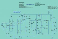
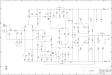
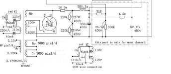
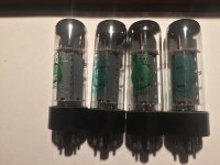
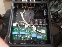
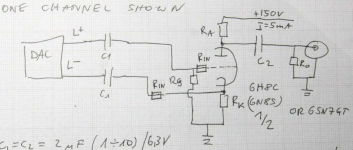
The 300B and driver portion of this amplifier derives directly from the exceptional Lux amplifier.

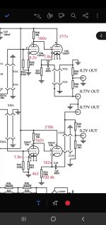
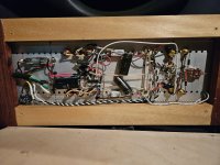
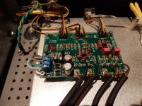
The input gain stage is handled by an EF86 – the classic high gain/low microphonic pentode.

Coupling is by one small high quality 0.015uf cap to paralleled sections of a dual triode 5687. The 5687 is direct coupled from the cathode to the 300B, providing a low impedance source to manage the 300B. This too is taken from the Lux, only the cathode choke is replaced by a high value resistive load with a large negative voltage supply.

This passes all the speed, delicacy and finesse of the pentode music amplifier to the 300B wile improving drive and overload capacity immensely.

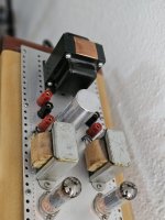
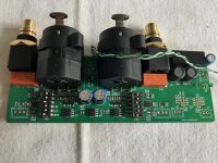
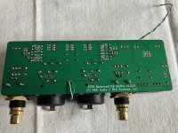
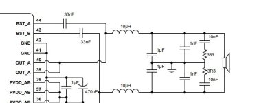
The 300B drives the speaker through the latest generation diyhifisupply output transformer, which is CNC wound for perfect lay, low capacitance and very wide power bandwidth and uses a high grade GOSS core. This provides the power output of around 10W, with matched speaker impedances of 4, 8 and 16 Ohm available.

Then, flick the Fusion switch, and the power (of the 8 Ohm Tap) is now boosted to 40 watts into 8 Ohm and output impedance is reduced from 3 Ohm to 1 Ohm!

You now have a 300B Amplifier that can handle any common HiFi and high end speaker well, not just high efficiency types!

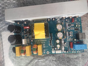
The Fusion's "Power Booster" is not a simple solid state booster amp with tons of feedback as sold by some, nor is it a simple follower circuit found so frequently in hybrid amplifiers.

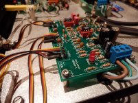
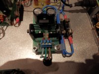
Designed by a noted designer of single ended amplifiers, the fusion's unique "current dumper" circuit monitors the current provided by the 300B section to the speaker load and adds ten times the current provided by the 300B section.

The 300B still drives the speaker through the output transformer and a high quality Kiwame resistor, from the 16 Ohm Tap.

There is no negative feedback, no solid state buffers added after tube stage as in most hybrid amplifiers - just added current and much less load on the 300B so it delivers more voltage cleanly to the speaker. The 300B still directly controls the voltage and current applied to the speaker directly and interacts with the speaker.

With a 16 Ohm Speaker around 25 Watt are available, an 8 Ohm Speaker can draw on 40 Watt and a 4 Ohm speaker can rely on 65 Watt being available.

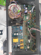
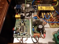
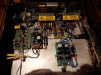
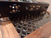
The Powersupply uses an over sized EI transformer with highly optimized choke filtered supplies.

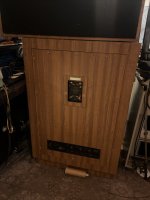
The large chassis and generous size dissipates heat evenly; it is normal for the chassis and power transformer cover to feel hot due to the efficiency of heat transfer from critical parts.

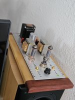
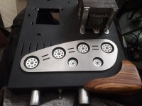
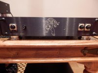
Did we mention the Fusion even looks good as well?

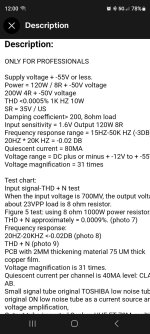
  • Power output 300B only:
    16 Ohm connection - 10W x 2 RMS @1khz < 5% THD
    8 Ohm connection - 10W x 2 RMS @1khz < 5% THD
    4 Ohm connection - 10W x 2 RMS @1khz < 5% THD
  • Power output 300B + Fusion Booster (on the 8 Ohm connection only):
    16 Ohm Load - 25W x 2 RMS @1khz < 5% THD
    8 Ohm Load - 40W x 2 RMS @1khz < 5% THD
    4 Ohm Load - 65W x 2 RMS @1khz < 5% THD
  • Frequency response: 6Hz to 60KHz (-3dB@10W)
  • Input sensitivity and impedance: 500mV, 100k ohm
  • Output Impedance Speaker Taps 300B driven: 4 , 8 and 16 ohm
  • Output noise: <1.5mv
  • Power Consumption: 110/230V AC, +- 10%, 90W
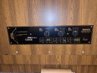
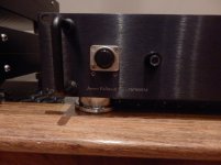
  • Control Functions: Front panel: Power On/Off, Top deck: Fusion in/out
  • Input Interfaces: 1 groups (RCA)
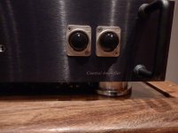
  • Output Interfaces: 4 Groups 4-way binding Post 0/4/8/16
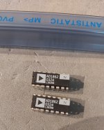
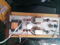
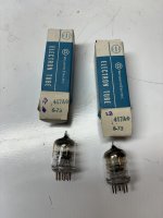
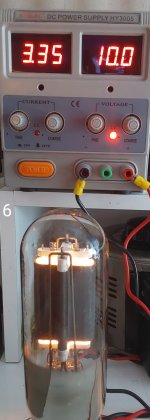
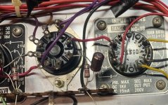
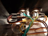
  • Vacuum tubes: EF86 x 2 or equivalent, 5687 x 2 or equivalent, 300B x 2
  • Dimension (mm) and weight: 340(L) x 410(W) x 230(H), 28kg net

Only available assembled

Stands for floor standing speakers

I have a pair of Altec Valencia speakers and would like to put them on stands so that when seated, the horns are at ear level. They have a footprint of 26" wide and 20" deep and 30" tall, they each sit on a 2" high plinth that is simply a wood frame made of 3/4" particle board.

I need to raise them about 12". What would be the best type of stand that would not diminish the bass response? Pedestal? Wood frame like the current plinth, only taller? If a frame, should I fill with insulation or maybe some concrete? Looking for some guidance.


altec-lansing-846b-valencia.jpg
  • Like
Reactions: jawen

Bad 12AU7?

Troubleshooting a chifi ms12b preamp, and i believe it has a 12au7 cathode follower for the ouput stage. I dont have a tube tester, but checking for a short with multimeter shows all tubes good. In circuit below, bottom tube appears to run away as getting same voltage at cathode as grid... cathode resistor in circuit measures well from pin3 of the tube base to ground, output caps replaced to be safe... kinda has me puzzled...

i guess my question is do tubes short with only higer voltages?

Or could the grid have opened creating the runaway?

edit;
Have new 12au7s on the way, but thought i should double check the preamp before putting new tubes in....

Attachments

  • Screenshot_20240220-112938_Adobe Acrobat.jpg
    Screenshot_20240220-112938_Adobe Acrobat.jpg
    155.8 KB · Views: 135

Audio detail

Would someone please explain to me why I hear better audio detail from my Samsung tv speakers or my computer speakers than I do from my mighty HPM 100s...?
Same source- streaming or CD...Different receivers...Denon 4802, Yamaha V3000...same result. Not sure what might be the frequency of drumsticks clicking to set the beat at the beginning of a tune but I can't hear them on the HPMs...WTH??

Need help understanding Audio Research's tube-hybrid preamps

Apologies as this may be somewhat broad, and I may be somewhat stupid.

As I understand, the first Audio Research hybrid preamp was the SP-11, which used several transistor/tube hybrid gain stages, in different numbers, for different parts of the circuit, with three in the line stage, for a total of six such stages used.

Then we get the SP-9, which has reduced the number of tubes to 2, one for the phono stage, and one for the line stage.

Later line stages such as the LS-25 and LS-26 use two tubes as well, this time both for the line stage.

I understand the basic four-tube line stage gain circuit. I assume hybrid designs replace one tube with a transistor (as in the transition from the LS-25 Mk1 to Mk2). So how do the single-tube designs work?

I guess basically I'm looking for an idiots guide to the topologies that ARC has used over the years. All I've found so far is Alex Megann excellent article about the SP-11 at http://soundmovements.co.uk/diyaudio/, and of course the wonderful arcade.ws database

Modifications (drive and EQ)

What is going wrong with the cheap

Pro-Ject Debut III Esprit and Cambridge Audio 651P ?


Sorry,
the first post is to give me some air. I'll report on the drive modifications later, first my annoyance about the EQ.

First of all, I haven't listened to an MM system for decades, I prefer MCs. But in the context of the OREAD project and other gimmicks, I had announced to buy the cheapest MM system and so on, interested people can read the thread about it.

Now the AT-VM95C is mounted, adjusted, everything is fine so far. A test run is needed, ok - I have to add that I bought a CA 651P some time ago, more or less in passing. What for, for comparison, comparison with my own products. But what a disappointment, countless equalizers ... My God, with an MC you could get something out of the product, but with the current test formation ... No, it distorts, it's slightly muffled, zero atmosphere, but above all ADELE 19 distorts like the plague.

Well, no problem, I'll take it apart and get to the bottom of the problem. Why am I sure that the CA651P is rubbish? Because I dusted off my old PEARL - I've never listened to it directly, only with MC-Pre.

The original Pearl 1 doesn't distort, it rocks ... My iPEARL rocks and simply goes off like a rocket.
What is going on with Cambridge Audio (?), nothing is really usable from this company(!) - and I have several products from them.


Anyway,
here in this thread I will publicly disassemble, analyze and modify the EQ - so that it works without failing at the cheapest MM.

Attachments

  • AT-VM95C.png
    AT-VM95C.png
    371.9 KB · Views: 122
  • iPEARL_No1_vs_CA_651P.png
    iPEARL_No1_vs_CA_651P.png
    417 KB · Views: 113

Crossover design. How hard is to add a Woofer to a 2-way and make it 3-way?

Hi everyone.

So let’s say I have a small bookshelf speaker and want to extend with a bass woofer resulting in a 3 way.
Is it a complete x-over design case ?

Theoretical cross point between midrange and woofer let’s say 400hz as a starting point
Speakers will be 15W 8530 K00 in sealed Enclosure reaching 80hz -f3 as a woofer and Sica 5.5 C 1.5 CP in another sealed compartmend.
Estimated x-over point 400-600hz (what is best )
Speakers will be crossed to Subwoofer at 80-90 hz and will never play without Subwoofer.
Spl should not be an issue , i am sitting max 1 meter from speakers.
I am planning on going fully active in the future but for now i need to make the Speakers (15w+Sica coax) work together passively)
Projects by fanatics, for fanatics
Get answers and advice for everyone wanting to learn the art of audio.
Join the Community
507,648
Members
7,882,654
Messages

Filter

Forum Statistics

Threads
405,961
Messages
7,882,654
Members
507,648
Latest member
nguyenbatrinh