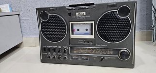
Hi. First preview of an upcoming pair of monoblocks, the Goldmund Telos 2500.
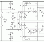
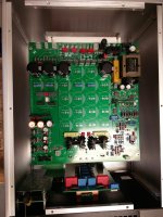
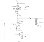
It is a long term project of mine, being working on that since the last 5 years, slowly putting together pieces of the design. I listened to a pair a few years back at the Montreal HiFi show and they sound superb! It was always a dream of mine to have a pair. The PCB design are my own, as well as the firmware. Never had a real Telos to look at. I compiled different schematics over the years, and saw the PCB silkscreen, so my parts location are close to the original. But since this is my own Firmware and control section, the rest of the amp has to match, and it is not an exact clone.
One of my problem was that the Telos use a processor and firmware to control the amp, and start, stop, switch between the different options (Mute, Analog or internal Dack, etc...) and safe shutdown in case of failure. This amp is very powefull, fast and can be prone to oscillation in some setup. So extensive protection is a must.
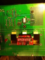
I wrote my own firmware using an Arduino Nano. My son a softawre engineer give me some help. The amp has sofstart (similar to Mark Johnson ACPRSS), multiple start option (Autostart on input signal, external 12V or dry contact). Mute function, etc... The small DSHP display controller, inclidng PIC code and PCB gerber came from this excellent site:
HDSP 2000 Display Controller Board - Instructables
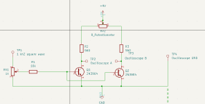
The Firmware is a State Machine, use two interrupts for the more critical faults (DC/HF & Overload) and stay in a loop after to check the remaining fault and control the amp (Mute, Digital/Analog switching, Dack Unlock/Lock indicator, etc) and the user interface (button, leds and optional display). Arduino controller is different from the original, use modern I2S interface bus and bus expanders. The Amp analog and Digital (controller) sections are completely separate and are isolated by opto-couplers. So no controller noise or dangerous analog supply levels can reach the controller.
It has more or less same interface as the original Telos: 2 buttons press power-on, 1 button for Mute, selectable Analog or internal Dac (optional), three leds for various indication (standby, Power On, Mute, Failure flash, startup sequence, etc...). I even add a small HP HDSP display module to display messages, such as Power-On, Firmware version, etc. It also display the heatsink temperature while in Mute. This small display is optional, and you'll need to get the difficult to source HDSP display. It is just nice to have since the amp is operating fine with just the leds display...
There are extensive protection and fault detection: Power Supplies Shutdown power Mosfet switches (as the original), Overload fault (using Current sensors, as the original), DC fault, HF oscillation fault, overtemp fault (an I2S temp sensor give in real time the actual temp) and speaker disconnect relay. I added a thermal AC disconnect switch in the main AC line as well as an extra thermal protection.
All these faults will shutdown the amp, a led will flash according to the fault code, and a message will be display on the display module. You need to power down completly the amp in order to clear the fault. Naturally the controller test for DC and Overcurrent faults at startup, so if a fault is still present the amp won't start...
The rear panel has Analog (SE/BAL) Input, Digital SPDIF In/Out connectors, ANA/DIG and Left/Right DAC switches, Gain selector rotary switch (-9dB, -6dB, -3dB, 0dB, +3dB, +6dB). It will also have external power On +12V or Dry Contact inputs, Chassis and Audio GND binding posts, and GND Lift switch)
Anyway this is just a preview, being working almost full time on this since th last 6 months (almost 3 months just to design the complex pcb). Presently I'm doing extensive testing, found all the pcb errors in my first prototype and finetuning the firmware. So far everything is working but I still have to check the DAC.
If there is enough interest I may offer this pcb set with controller firmware as a group buy... Kit will come with complete detailled BOM, PCB silkscreen, interconnect diagram, Spice model to look at the actual circuit behavior, voltage and current, detailled testing and startup procedure, step-by-step and per PCB. Complete kit has these PCB: Main PSU/Controller PCB, Front Panel PCB, Input/Front End PCB, Output Power PCB and a few smaller accesories PCB such as the I2S temp sensor, and optional smd to DIP op-amp adapter. The internal DAC PCB will be optional, as well as the HDSP display PCB with PIC controller.
As I said the internal dac may be an option, you can drive the amp directly from a music server, and operate in the digital domain up to the amp, as using JRiver and computer for example. The Amp has a SPDIF input and you can select what amp play Left or right channel. A SPDIF digital output then connect to the other amp. I'll make a set of DAC pcb for me, but I still need to test the prototype. Dac may also be available (all smd, very small parts design) so if you don't like smd, I guess you don't want it...
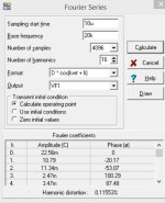
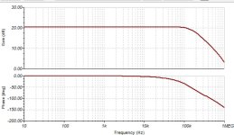
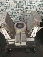
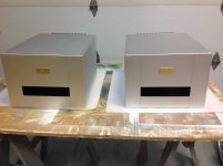
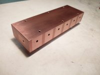
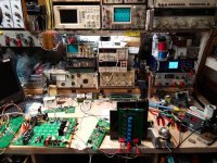
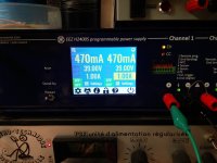
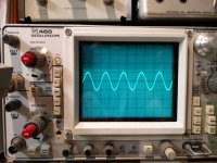
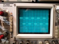
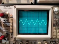
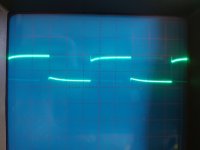
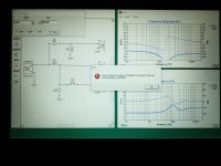
Here a few pictures. Prototype is working fine on my lab power supply, 470ma bias for 6 parallel Mosfets, 78-80ma per Mosfet (Exicon ECW10N20 & ECW10P20, selected part directly form Profusion, UK). This is a low power test, 2 Vac/1Kz into 8 ohms. Output waveforms are prefect, no oscillation, see waveforms. The output stage MOSFET are closely thermally coupled being mounted on a copper block, that is then bolted to the rear heatsink. The original Telos use the same arrangement, but thier copper block was gold plated. Mine is just protected by clear lacquer.
More to follow. Once I have a complete, runnning, assemble amp I'll update the thread...
SB