5U4G minimum supply impedance, (cap vs choke input)?

What is minimum plate supply impedance all about? The 5U4G tube specifies a minimum of 75 ohms per plate for a capacitor input supply. But I'm doing up a choke input supply with: TOROID (full wave) --> 5U4 --> 15H --> 40uf. I'm assuming I don't have to worry about this parameter when doing choke input, correct? The reason I ask is because my transformer is a toroid and I know those have less impedance than a vintage EI transformer. Is the minimum supply impedance restriction specified for safety or longevity of the tube? I remember as a kid we had a TV set where the 5U4 would literally explode, happened twice, then dad junked the TV.

My toroid has 3.5 ohms primary DCR (with coils in parallel for USA 115v). And it has secondary DCR of 80 ohms (40-0-40 ohms). 40 ohms is way below the 75 ohms per phase in the data sheet. BUT the data sheet only lists minimum supply impedance for capacitor input PS. Final question... Am I okay using this 40 ohm toroid for a choke input supply since the data sheet doesn't mention this parameter for that topology?

https://frank.pocnet.net/sheets/127/5/5U4G.pdf

Bricasti M1 processor - modification.

Moved from another thread....

I have this dac (Bricasti M1) and I like it very much, but to my ears the treble (slightly) lacks ultimate resolution and sweetness compared with my other dacs. On bright and older recordings it can tend to be a little "unforgiving".

Taking a look at the pcbs's I noticed AD843 op-amps in the IV and buffer stages. These op-amps are not noted for audiophile qualities but they are advertised for high speed applications including 'high speed integration'.

In an effort to add some sweetness I decided to bias all of the op-amps into class A. I did this by adding a CRD with a series resistor from the op-amp output to the -ve rail. (4 per channel) I mounted them on the underside of the pcb so as not to deface the aesthetics. The resistor was used to set the v drop across the CRD to the mid point of the linear region, which for the specific 2mA CRD used was 8.5 vdc.

Because the op-amps are all paired from the diff outputs from the dac, I decided to batch test and match the CRD's to <1%, which was possible because I had a large stock on hand. I also found that the CRD's ranged in value from 1.7 to 2.3mA, but nominally 1.9mA.

I also tested the current sink regulation over a 3V range and it was a creditable 99.8%.

While I had the dac apart I also passed a cursory eye over the linear power supplies which are all discrete types using op-amps to generate references and with tip120/125 darlington output transistors.

I noticed that a 104 film cap had been installed across the bridge rectifier input (transformer secondaries) and another at the bridge output, but there was no series resistor with the input 104, so it obviously isn't an effective "snubber". This seemed odd, so I subsequently unsoldered one side and added a 330r resistor in series ( 2 per channel), though I didn't use the cro to check, from past experience those values are usually effective at damping any ringing.

OK, so how did it sound after this change you might ask?

Actually, I was very surprised to hear such a big change, because frankly, I wasn't able to measure anything substantial on the pc based analyzer. (distortion was already a low 0.001%)

However, the treble is now MUCH sweeter and more pristine than I could have ever imagined possible, and all of those bad old recordings are now very easy on the ear. It's now every bit the equal, and then some, of my Berkeley Alpha 2 in the treble and is easily the best overall and least 'digital' sounding of all my processors. I also now prefer to use the linear filter set rather than the minimum phase set.

It's worth noting though that I made two changes at the same time, so it's difficult to ascribe the contribution from each, but I'm assuming it's the 2mA of bias on all op-amps that's been the major factor.

I can't say that this same modification will be as effective for all op-amps, and / or in other implementations, but it's nonetheless worth experimenting with based on my personal experience.

Hello from Toronto! Aspiring DIY Speaker Builder

Hi Everyone! I'm Michael from Toronto, Canada. I'm a beginner speaker builder and novice audiophile. I've been lurking in the forum for a good few months now and decided I should start and participate in some of these really interesting conversations. A bit of background on myself, I started building speakers near the end of 2021 as a way to kill time during pandemic lockdown with no idea how deep this amazing rabbit hole really went. Maybe an interesting fact? I'm under 25 which makes me part of the minority age AFAIK.
The first pair of speakers that I built were modeled (very roughly) after the PS Audio FR30, but with very little real speaker-building knowledge. I think they sound great compared to anything else in my home or any of the other speakers in my friend's homes but my opinion of them will probably change as I build more speakers and learn new things.

Anyway just thought I'd say hi before I get involved, see you around!
4A706897-F7A8-4898-9F87-C799BA3A7AC4_1_105_c.jpeg

Speaker Power vs Amp Power

Hi,
I have combed the internet without an answer for the below and hope someone can give me an answer.

I am making a chip amplifier, LM6886 68W per channel, powered by a toroidal 28V 250W. The speakers I have are rated 8 Ohm, 250W, 8 Inch full range (+tweeter). My intension is to listen to (high) quality well balanced music at low sound levels, without distortion.

I have read - if the speakers have a much higher wattage that the amplifier then there will be clipping, sound will be distorted, sound will not be lively and etc. There are lots of answers about sound quality but no explanation to the reason. I'm searching for the reason for this quality drop. Can someone please explain; why does a higher watt speaker create sound quality issues.

Please your answers will quench my thirst for knowledge also consider buying (new) speakers.

MTX Thunder "elite style" 92001 resistor value

Working through this one, and pads R4082/R4087 have a single 3w resistor soldered between them. The resistor runs 300+F degrees and smokes slightly and is discolored and discoloring the board. I'd like to replace this resistor with a 5w. Off the board this resistor is measuring 7.8k, but looks like this is either a 10K or maybe even a 10/100/1000 ohm resistor. Any idea what the value is supposed to be?

Threshold ns-10 cap replacement

Hello to all, I wanted to ask some of the pros on this site about a good recap for my threshold ns-10 I would like to substitue the tantulums for modern day replacements. I put some Panasonics in the pwr section they had stuff coming out and looked like they were going to explode....but not sure what caps to put in other areas of the preamp.IMG_1174.JPG
IMG_1156.JPG
IMG_1174.JPG
IMG_1184.JPG

Attachments

Mundorf Mcap Supreme EVO as bypass. Is outsie foil plus or minus?

Hey
The power supply of my tube amp has 3x 220uF electrolytic capacitors. I'd like to bypass those caps with some Mundorf Mcap Supreme EVO 0.1uF. Mundorf website states: "
the longer lead also indicates the capacitor’s outer foil."

So, should I solder the longer lead to the positive or negative pin of the big electrolytics?

I know that the outer foil should point towars the lowest impedance point but Idk if positive or negative has lower impedance.

What to build: FE108Σ

Hi all,

I've come upon a nice used pair of Fostex FE108Σ. I am interested in your input and suggestions for a cabinet for these. I am interested in running them as a single full range driver.

If you can recommend a build that works well for these & have personal experience on the build and better your own listening experience - I would be very grateful for your sharing!

Simpler is a bit better, but if it is consensus that there's too many benefits for a complex build (e.g. Scott Lindgren’s - Aiko) then so be it. I've tools and experience as a cabinet maker and boat wright so the build doesn't daunt me, it is just that I'm undertaking another large build in making a pair of Dick Olsher's Basszilla and already have all the drivers, but haven't started the furniture or buying the crossover parts. I don't want to get bogged down in another build, but really think it would be fun to get these little Fostex up and running.

Designs that I've considered include:
Simple bass reflex - volume and port tbd
Scott Lindgren’s - Aiko
Frugal Horn Mk3
Metronome 1V1.01

I listen to (almost) anything, as long as it's good.

Thanks,
Tom

DD DMF2800

Hi Guys

I got a DD DMF28 but not sure of the correct o00. On opening and inspecting the amp I found that diode D4c3 was missing. I did replace it with a 1n4148 but not sure of the correct orientation. I also found c107 missing

2800 diode.jpg

2800 cap.jpg

2800 board.jpg

Could someone please help with this or if you have a circuit diagram please could you share it.

The fault as per the customer before he gave it to someone else to repair was that the amp started playing at low volume. he said that at first the amp played well and when the fault started he had turn the gain to full in order to get sound to come out and on his head unit he had to the turn the bass up to full as well in order for the amp to play loud. He is using 2 DD 12" redline series wired at 2 ohms to the amp.

Now I know that most of the time with this fault it is the drive ic that could cause it. I have not switch the amp on yet just want to have the correct components on the board and also want to redo the crappy solder work on the all the components.

thank guys in advance

Scope readings.

Get this sort of readings out of the driver tubes in my 300B push pull amp. The driver tubes are ECC99. The amp has been working perfectly for many years but one day the amp got distorted and a bit low in volume. When measuring all voltage they seem to be ok. Tried a new set of input and driver tubes but it didn't help so clearly I`m overseeing what should be the obvious.

Scope img..jpg

Accelerometers to measure panel vibrations?

Where can I buy one of those? I can find a lot of information, but all old. And I don't have time go get into some DIY construction project about it.

I plan to make some cabinets, and want to experiment with damping, bracing, coating. Therefore it would be really handy to have an accelerometer of some kind (I'd hope connectable to Mac or iPhone) to quantify improvements or lack thereof

Advice on balancing direct outs

Hey gear geeks,

I’m unsure if this forum is for audiophiles or if it also includes pro audio gear. Anyway, i wouod appreciate if anyone could of you smart people could go over this idea. My smooth brain doesn’t know how to implement this idea correctly.
So i have a great studer clone with insert points on its 6 channels which are used with a stereo/trs connector for both return and send. The signal is therefore unbalanced.
Now I got my hands on 6x Lundahl 1527s which I intend to use for balancing these insert points, thus feeding them as direct outs into my AD converter for recording purposes.
So far, so good. However I would also like to use this “balancing box” consisting of the Lundahls for mixing, when I finally sum the recorded tracks into my board for final mixdown. I’ve read a lot about how and why old neve desks sound the way they do. Basically one sound passes through about 7-11 transformers before getting printed to tape and going back through the same amount again for mixdown. Those are two trips through large quantities of iron.
I want to build on that idea and use a similar signal path on my little studer clone. The idea would be to run the unbalanced signal of each channel out to the tranny and back in, thus adding flavour over 6 channels. I would like to use my TT patchbay for this, which has the option of half normalling signals. It is an old Neutrik patch bay with individual soldering points.
What I would want is to have it normalled so the inserts the mixer do a roundtrip and run back into the mixer. As a secondary option I would want to add the option of connecting 6 cables and that making the direct outs connect to the AD converter.
Is this possible? I am pretty decent with the soldering iron now and also open to mod ideas of both patchbay and a potential secondary box if needed.
Thank you for reading.

Mr Liang Sound Luster D-2030A Hi-fi power amp w/ KT88 tubes for sale, low hours usage, probably under 100 hours. No tubes out. $595 cash.

Excellent condition, lower hour use, I would state around 100 or less. If you are looking for an excellent power amp you can't really do better for the money in the price range. The ONLY issue I had was that the plug in the back cracked and I replaced that easily, as you will see in the photos, with a much better and more solid plug.

I know I am new to this site so I am willing to work with the buyer to make sure they are satisfied. It's difficult to guarantee a tube amp when you are shipping it cross country but we WILL work something out so the buyer is comfortable. I have tons of photos.

My contact # is: 218 513 0049 and if I miss your call, PLEASE leave a msg as I am out in the garden a lot right now readying it for summer.

IMG_20220514_105119 (2).jpg
IMG_20220514_105140 (2).jpg

Attachments

  • IMG_20220514_105235 (2).jpg
    IMG_20220514_105235 (2).jpg
    235.3 KB · Views: 118
  • IMG_20220514_105155 (2).jpg
    IMG_20220514_105155 (2).jpg
    301.1 KB · Views: 106

I need help with a Lite Audio DAC-38

It was given to me along with a pair of F5c V2.0 (cascode edition) and a special for pass PSU along with a pre-amp.
All but the preamp were 70% built, but it also has been modified by the previous builder, and since that person past away, I have no clue as to what exactly he's done to it and why... Nonetheless, I went on a mission to find the somewhat hard-to-find chips and found them all... That's all done now and the DAC is completed. But, it doesn't work... So here I am asking for advice and help!

Does anyone have a schematic for it by any chance? any suggestions about what might be causing it to not work? It powers but no sound at all!

sorry for the number of pictures

F5c.jpeg
psu and F5c.jpeg
psu1.jpeg
dac_mods.jpeg
dac_mods.jpeg
dac2.jpeg
dac3.jpeg
dac4.jpeg
dac1.jpeg

Kenwood Remote Control Unit RC-R0607 range dropped

My Kenwood Remote Control Unit RC-R0607 controlling a Kenwood AV Receiver VR-208 dropped to very limited control distance.
KenwoodRC-R0607.JPG

Worked normally from the couch at about 2-3 meters, then after not being used for a few weeks, the range dropped to about 66 centimeters (26 inches).
Batteries are good.
Indicator light looks bright when any function is keyed.
Transmitter and Receiver’s surfaces are clean- cleaning made only a few centimeter distance in range.
All the RC functions work at the reduced range.
Percussive maintenance (whacking the RC on a table) does not change the range.
The RC uses LED IR emitters on either side of a (visible) power indicator, if either side is covered by hand, range is further reduced.

1) Is it possible the problem is with the Receiver rather than the RC-R0607, and if so what would cause it ?

2) The one visible capacitor when opening the unit looks OK.
Any ideas what would cause it to loose range, or “quick fix” possibilities?

Thanks,
Art

EAR 859/869 inspired amp build.

It has been in my stars to make an 859, even though I was not totally smitten with it the first time.... Fast forward almost 30 years and several 3-6 watt SE builds later, I figured an 859 at 12 watts seemed like an idea. But really heading towards 20 watts would be more satisfying, and the nearest TX I have is a nominally 20 watt chinese, at 3.5K, rather than dp's 4.6k, so I came up with the idea of running the 509 in parallel with a PL504, which seems superficially like half a 509 spec wise. This build has been rumbling in the back ground for a while, whilst still building up courage and accumulating parts for my 13E1 and GM70 SE amps. A little iron related pause on my PP triode amp, has spurred me back on tho the 859. It is more of an 869, with improved bias stability loop by the LTP input stage,
http://www.troelsgravesen.dk/EAR-869.htm
thanks Troels for posting the circuit. I have had to mod it a little because I can't help myself and to cope with the extra tube into the DC loop. This is additionally complicated by another bright idea, Eco mode. I live quite happily with 3 watt SEs 95 percent of the time, and I know myself I will not be putting on a hefty tube guzzler for background listening, so I have arranged to be able to switch out the 509 by turning the heater off.

IMG_20210904_194947209.jpg


Well it is almost working, after a bit of head scratching over the DC loop being very saturated I realised yesterday I had some 22ks instead of 2k2s in the output tube's G1 potential divider, and had the cathode follower divider upside down as well. That fixed, it burst in to life. Now I optimistically figured I would be able to get away with 450V HT, but that isn't going to work, and I have exploded one 450V cap so far. with both tubes running it gives around 11 watts. I need to jack up the HT to around 530, similar to dp's value to get the desired output. This is going to need some higher voltage re-capage, nuisance.
IMG_20220325_183102864.jpg

Heater test, A problem in itself with 6.3v 40v 27v and 42 volt tubes.
IMG_20220223_204636435.jpg

To be continued.

For Sale Ming da KT120 Ultralinear/Triode MC368-B Integrated Amplifier

I bought this a few months ago from someone in London. It was working perfectly when I bought it but after transporting it home it developed a slight hum in the left channel. After speaking to a few people, I tried to move the valves around to see if that would cure the hum but unfortunately, it didn't and now there is a hum in both channels. It's not audible when playing at decent volume levels but that's obviously a subjective evaluation so would recommend taking it to Mark at Ming Da UK in Malvern for a once over/service.

I'm selling because I'm now more interested in building my own amplifiers and I need to raise money for projects and this won't get the use it deserves.

Here is the blurb from the original owner:


"""

All new valves. Renown for their excellent high spec transformers, that really make any amplifier.


The original KT88's have been replaced/upgraded with a new set of KT120's Tung-Sol's, Chinese valves replaced with 4 new x JAN Philips 12AU7's and a Mullard ECC83.


The valves here alone cost over £300!


All old caps and electrolytics have beed removed, and replaced with high spec AuDyn Reference Caps and a bucking Transformer to deal with UK 240V. This is a genuine UK version, not direct from China. It has been verified and updated by Ming Da UK, with their stamp and Bias settings.


This amplifier is at it's peak; Powerful, able to be switched from Ultralinear mode to Triode mode, able to drive almost any speakers with those KT120's: Better than the KT88's with more headroom and power. Well worth an audition.
"""

I don't have a car so it wouldn't be straightforward for me to take this to Mark but it might be easy for others. Given that I don't know the cost of service and Mark couldn't say without looking at it, I'm not quite sure how to price it. I bought it for £750 and had to pay around £40-50 to get it home in a cab.

I think £650 seems like a reasonable starting point but if others think that's too much and I need to adjust the price, I will.

Probably an easy fix for someone on here.

Will have to be collected only from Bristol due to the weight. If someone wants it and is happy to collect it, then Malvern is about an hour's drive from Bristol.

Attachments

  • m10.jpg
    m10.jpg
    312.3 KB · Views: 144
  • m9.jpg
    m9.jpg
    251.5 KB · Views: 175
  • m8.jpg
    m8.jpg
    94.4 KB · Views: 163
  • m6.jpg
    m6.jpg
    251.4 KB · Views: 163
  • m7.jpg
    m7.jpg
    199.2 KB · Views: 153
  • m5.jpg
    m5.jpg
    199.2 KB · Views: 145
  • m4.jpg
    m4.jpg
    199.2 KB · Views: 138
  • m3.jpg
    m3.jpg
    226.5 KB · Views: 140
  • m2.jpg
    m2.jpg
    153.8 KB · Views: 135
  • m1.jpg
    m1.jpg
    401.8 KB · Views: 138

Jolida SD/SJ 202a …. Looking for an output transformer or substitute of same dimensions.

Hi guys, I managed to blow my right output transformer on my Jolida SJ/202a int amp.
it is a 40wpc, EL34 tube amp.
Does anyone know of a correct substitute for this amp?
I called Mike Allen of Jolida, but no stock available.
My technician is finding a challenge in sourcing one of the correct size.
The dimensions are 3 3/4”t x 2 9/16”w x 2 11/16 d

Attachments

  • AE18F003-999A-484F-B0DE-D57B9BA4724F.jpeg
    AE18F003-999A-484F-B0DE-D57B9BA4724F.jpeg
    475.8 KB · Views: 147

Oscilloscope-probe isolation with transformer?

For measuring SMPS-primary side voltages I could really use a isolated probe with at least 1mhz bandwith. Thats not DIY-stuff if we look at components like AMC1200 ( 100Khz BW).

BUT, for checking SMPS primary often we dont need DC, we dont need high accuracy and we often dont need high impedance input. - SO could a transformer-coupling work?

I'm guessing that most of my needs could be met with 1(10?)Khz - 1(10?)Mhz +/- 3db and 10K-input impedance IF the setup had 4Kv isolation and low capacitive coupling.

Have anyone been down this path?

Kind regards TroelsM

H bridge & odd harmonics rejection

Hi everyone,

Thank you for all your advices in this forum, that's splendid !

I'm currently building an H-Bridge Amplifier. I'm a beginner in the conception of amplifier but I'm starting to understand the mood !
In this project I do have a bill of specifications such as using an asymmetrical alimentation (will be a PC one) and using ThermalTrak as output transistors so don't be surprised.
I've almost finished it, but I have encountered a problem with the THD. I am at almost 0.2% at 20 kHz (0,013 % at 1kHz) on each part of the amplifier that are inspired from the Blameless amplifier of Self, and same THD for the output of the H-Bridge.

I know that H-bridge is supposed to reject odd harmonics and so, reduce THD, but there it doesn't. I have connected the 2 amplifiers in parallel, one in non-inverser configuration, and the other in inverser. On the second one, I have adjusted the closed loop gain a bit differently so it could be almost the same amplitude at the output than the non-inverser.

Could it be there the problem of non-rejection? Or maybe the poles are different on each amplifier which affects the output. Don't really know.

Do you think we could reach the odd harmonics rejection with this topology of H-Bridge amplifier?

Thank you a lot for your help.

Attachments

  • H-bridge-sch.png
    H-bridge-sch.png
    35.9 KB · Views: 171
  • H-Bridge.zip
    H-Bridge.zip
    25.1 KB · Views: 89

Stream from local NAS to WiiM mini?

Hi. I’m somewhat new to streaming. I set up Volumio on an RPI and used USB to my Schiit Modi and that worked well. My main source was a USB thumb drive with flac files I ripped from my CDs. Then my son gave me a subscription to Amazon Music, and Volumio doesn’t stream that. I tried using AirPlay from my phone to Volumio and that didn’t work well. So I bought a WiiM mini. It streams Amazon Music well. I’m using the toslink to the Modi
Now I still want to listen to my flac files, I’ve got a ton of them.
My question is (finally!): what’s the best way to stream the flac files to the WiiM mini? I could set up an RPI as a NAS with a 500Gb drive for the files - will the WiiM mini just see them? Or do I also need to put a media server on the NAS like Plex or something similar in order for the WiiM mini to stream the files?
Thanks, Rob

Can I use a 2 way crossover as a 1 way crossover?

Hi I have a Beyma FD212 two way crossover rated at 1200hz. In the interest of bi amping and a somewhat unusual configuration, I'm curious if I can use this crossover in a 1 way configuration. The implementation and question is as follows: Can I send a full range signal out of a dac to an amp and in turn directly into the crossover's input, bypassing the woofer section of the speaker? And in turn send the output of the crossover to a 1.4" compression driver? Thanks for the help.

LTSpice simulation for balanced inputs - DC offset question using NE5532 and LM3886

I am having hard time simulating a schematics - sometimes it shows DC offset at the load, and sometimes it does not. I am confused as to why LTSpice is not consistent with the simulation calculation.

I have tried a circuit with DC blocking capacitor and then without. And I am getting mixed results running one or another scenario multiple times. When I put together simulation first time I did not use DC blocking capacitor and when I measured load voltage, it started from strictly 0. Now, it is offset by -37mV.

When I include DC blocking capacitor, DC offset is -4.5mV.

I guess my question is - can I avoid using DC blocking capacitor?

Can someone help me with this? I am attaching schematics file with model files for both amps.

Thanks,
Pavlo

Attachments

Hello from the great state of Minnesota!

Greetings from the 2 season state of Minnesota: mosquitoes and snow! Last week I had snowstorms, this week I have 75 and thunderstorms and tornados. There is no moderation here! Nonetheless, I love the state and beauty of it, as well as the wilderness it offers. If you want to get away from people here, you can, easily. Lots of lakes for fishing and the Boundary Waters Canoe area is epically known for its incredible quality camping, fishing and just plain all around great get-away-ness.

No, I haven't been hired by the State of MN to lure you here, but you are missing a lot if you havent visited the state or dont plan to. A good example is Grand Marais or Duluth. Both are high standard tourist spots.

Electrolytic Caps...DC bias vs Signal throughput.

Hi Everyone. I was choosing whether to use a Non-polarized cap instead of a standard (audio-grade) electrolytic capacitor. I was wondering if an electrolytic cap needs to have a bias voltage GREATER than the the AC peaks of the signal it is passing? Scenario: You want to block a DC offset say of 0.5V but the signal might reach peaks of 1V. In this set up I see the capacitor is subjected to minus 0.5V on the negative swings of the signal. Question does this matter? OR should I use a non-polarized cap? I've seen lots of audio circuits (mainly on the signal outputs of op-amps) that this might be occurring yet ordinary caps are used.

Sub recommendations for multi-sub system ?

Hi All,

I wonder if I could get a bit of input from people on trying to choose a model of subwoofer that would be suitable for use in a Geddes style multi-sub system where the primary purpose of the subwoofers is modal smoothing in the room for music playback rather than the typical home theatre "one giant sub to shake your house" approach that many subwoofers seem to be designed for.

Those who've read my posts before know I love ground up speaker design and currently have a new 3 way design in progress, (although semi on-hold due to circumstances outside my control) however for whatever reason I have zero interest in designing and building my own powered subwoofer, let alone the time to do it when I can't even find time to progress my 3 way design.

The main speakers which will (one day) be my main system are going to be a large floor standing 110(ish) litre bass reflex 3 way system - 12" woofer, 8" full range driver for midrange and ribbon tweeter.

In terms of bass response these will be tuned to around 25Hz and will have an early gradual roll-off alignment that will give a response that is about 6dB down at 25Hz before room gain is factored in, in short these should be good down to at least 25Hz in-room probably a bit lower and at a reasonably high SPL, as the ports will provide significant loading and gain vs sealed from around 20-40Hz.

So I won't need subwoofers to supplement the low end response of these speakers nor maximum SPL, however I will benefit from subwoofers to help with modal smoothing, as there are significant standing wave/boundary cancellation issues in this room that I can't do anything about passively, and speaker/listener positioning is extremely constrained by the size of the room and other stuff in the room.

It's a small British living room with a bay window on one end and the main sofa directly against the back wall. The front to back wall is 4.3 metres (hence the 40Hz fundamental mode) sideways its 3.8 metres, but 4.5 metres if you include the bay window in the left hand wall from the listener perspective. On the right hand wall is a 2 seat sofa and in the bay window there is a chair.

To its benefit we have high 2.8 metre ceilings, which does seem to help a bit with acoustics at higher frequencies and increases the room volume significantly for the small footprint.

The internal and external walls are all solid brick and plaster so not good for standing waves however the floor is a beam suspended wooden floor (with nearly a metre of crawl space and then dirt below) with carpet and the ceiling is gyprock / plasterboard suspended from wooden beams with some loft space above it and a second suspended wooden floor over parts of it as well.

So while the walls are bad for standing waves the floor and ceiling are probably quite good. Standing waves are still an issue but not as bad as a previous house I lived in with brick walls and carpet over a concrete floor which was really problematic...

The 2 way speakers I have at the moment only go down to around 40Hz and unlike the eventual 3 way design to replace them have the woofers high off the floor, which tends to exacerbate boundary cancellation issues.

The main issues I have are:

1) Large peak at 41Hz on the order of around 10dB at the listening position that has to be pulled way down with a PEQ, which then causes a hole at that frequency in other locations in the room. To fix this I probably need at least one subwoofer on the back (listener) wall to cancel the fundamental mode since a woofer in phase at the back wall would reduce the response at the back wall by the listener but increase it in the middle and most other locations in the room.

2) About a 6dB peak at 71Hz which I likewise pull down with a PEQ. I presume this is something to do with the ceiling reflection but I haven't really tried to work it out.

3) A big hole around 80-90Hz - almost complete cancellation at the listening position, and this is one of the things I'd really like to address with a multi-sub configuration as I can't do anything about it with EQ.

4) A nasty peak at around 105Hz which makes bass sound congested if I don't correct it with EQ.

5) A large depression right from 120Hz to 180Hz or so presumably due to boundary cancellation from the wall/corner behind the speakers, and I assume this would only be correctable by a subwoofer relatively close to the main speakers (due to the high frequency) such as the front right corner of the room about a metre from the main right speaker.

This depression can cause a lack of warmth on some material especially if I fully correct the nearby peak because there is not much energy between 100-200Hz once that 105Hz peak is corrected. (As a result I only partially correct the 105Hz peak until it doesn't sound congested to avoid losing all warmth in the upper bass) I would really like to do something about this depression in the 100-200Hz range.

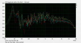
Interestingly because the bay window makes the room asymmetrical no matter where you put the speakers, (in this room orientation) there is a big difference in the boundary cancellation of the left and right speakers. This was measured at the sofa at ear height with no gating so ignore anything above 200Hz:

976828d1629625787-sub-recommendations-multi-sub-system-modes-png


As can be seen the left speaker (red) suffers considerably more severe cancellation (including 55Hz, 130Hz etc) than the right speaker or the summed response. This can sound a bit weird when a note at 130Hz is coming primarily from the right speaker for instance.

There are only really 3 places subwoofers could fit and work in with the furnishings.

One is to the left of the sofa where there is a 50cm gap to the wall which currently has a 45cm high table for a lamp, pot plant, remote controls etc, so a subwoofer of around 45x45x45 cm would fit there if it had a flat, wood grain top which could double as a table. (Egg shaped subwoofers need not apply)

The second possible location is in the far right corner near the right speaker, where there is a fair bit of room now that a toy chest is gone. It might have to have a pot plant standing on it as well...

The third possible location is to the right of the speaker part way up the right wall beside the side sofa. This one could be no bigger than about 40cm x 40cm x 40cm to fit under a small table that is there and clear the door.

So, what models to consider ? I'm not looking for a large sub home theatre style, several smaller subs with the same combined output of one large sub are much more suited to the multi-sub approach.

While I only want to buy one for now so I can make a useful improvement to the cancellation / bass issues I'm having with the current 2 way system and use it as a testing tool to measure the performance of different locations in the room, it needs to be cheap enough that I can afford eventually increasing the number of subs to 3, both for use with the current 2 way system and ultimately with the new 3 way system.

Features I'm looking for - discrete box shaped sub with a flat top surface that is either black or wood grained suitable for putting a plant on top of etc, and preferably with either a cover over the woofer or down facing woofer to make it look discrete. There needs be at least one side that doesn't have any controls and is either blank or has a cover over the woofer for aesthetics and also protection from an inquisitive 5 year old.

Adjustable low pass frequency, level, phase and auto-sensing power on. More advanced EQ would be nice but I doubt anything in my budget range would have that.

I already have a DEQ2496 on the system for overall EQ so after sub level matching, low pass filter settings, phase etc are all optimised as much as possible I can "clean up" the remaining bass balance with the DEQ2496.

I know pretty much nothing about what's out there in commercial subs and most of the reviews I've looked at are written for lay people by people that don't have any technical knowledge of speakers themselves so I'm hoping that I can get a few pointers of where to start looking...

Attachments

  • Room Modes.png
    Room Modes.png
    89.5 KB · Views: 1,106

Hifonics BXi 2000 D

So I´ve got this Hifonics BXi 2000 D that is working now half-way.

Amp was already broken down, parts missing when i got it.

So i desoldered the output fet´s (not the same batch)

Power supply board was missing half of the vias on the underside of the board. So i just cut the pins and gave it a new "pinline" as I couldn´t desolder it.

I used IRF44Z and 47Ohm Gate-Resistors, old fets were already missing, Gate-Resistors slightly burned. Amp pulled 10A from my supply. Found out that the driver transistors on the board were mixed NPN/PNP side, drive signal was bad. Soldered in new driver transistors in the correct setup and got a clean Squarewave drive. So the supply side was fine so far.

Output board driver was bad, nice spark at the Output fet´s (IRFP250N). Desoldered the board and soldered in a new driver (IRS21844S)

Relais didn´t switch on, it switched before so i wasn´t sure what I destroyed now. Figured out that the Relais pin on the PS board just wasn´t making contact with the board.

Tested the board without load, it produced a clean sinewave with 50Hz to clipping. Then I tested it with 4,3Ohm and 1,6Ohm it worked to a certain point.

Gain in the middle position. With the 4,3Ohm it started hissing at 4,5V Input SineWave 50Hz.


44,8A from the Supply, 10,6A/44,5V at the output. The output signal get´s distored at that point.

With 1,6Ohm it starts hissing at 2,9V, 66,7A from the supply, 19,6A/27,3V at the output.

Both started making noises at a controlled point in 100mV steps. 4,4V were ok at 4,5 it started, the same with 1,6Ohm.

Then I tried it with a speaker, it just destroyed the speaker without even giving it a signal.

So my question is if someone experienced something similar?

Is the Output Drive still bad? I have 33mV DC at the output without a speaker.

I used a normal speaker, not a bass speaker if that makes a difference.

A bigger speaker didn´t die (I switched it off before it could reach that point?) but it build up noise, started oscillating? When I turned the amp off a higher tone was heard from the speaker. Much higher than I would expect from a bass amplifier.

Will make some pictures from the oscilloscope tomorrow when I can find my USB-Stick.

Thanks for reading and maybe an answer.

Will upload pictures later.

Polk power port technology. Does it really work

I came across Polk power port technology they use in some subwoofer and speakers.

Found this discussion online. Wanted to hear what people think about it and why is it not used by other manufacturers if it's such a great idea


Looking to use it instead of a port in a 2 way bookshelf speaker with 2 midbasses and a tweeter.


XXX18PPP (1).jpg

Cello Audio Palette

Cello Audio Palette clone - My Photo Gallery

P1010434.JPG

P1010421.JPG

P1010424.JPG

P1010425.JPG


For years I have dreamt about this beautiful and versatile preamplifier.
However the pricetag of some 16-17.000 $ used on ebay + transport from the US kind of kept me from it.
So what other thing could I do than clone it.

The Audio Palette
The Cello Audio Palette was a six-band equalizer that came alone or with a build-in preamplifier.
It was the based on Richard Burwen many years of experience with equalizing, and was introduced as the only high-end equalizer. The Cello brand was Mark Levinsons comeback after being thrown out of ...Mark Levinson.
Now equalizers were not – and are still not – considered to be a component that belongs in a high-end system. (This is probably the reason why Cello chose to call it an Audio Palette and not an equalizer). Music lovers (thinks they) want the pure and clean original sound, and do not want to add any un-necessary circuits into the signal path, which might introduce more distortion and noise.

But first of all – this one was different.
Besides it was actually Mark levinson that invented the no-nonsense line, by removing bass and treble potentiometers from his amplifiers. However not many people know the actual reason, but in an interview Mark Levinson said:

” Even though Levinson pioneered the 'straight line purist approach' to audio, he feels that despite the extra path that the signal must pass through, the advantages of the Audio Palette far outweigh the disadvantages. "A purist philosophy does not mean fewer dials. I am not of the purist philosophy - I founded it! I never said that equalizers were bad, I just said that we don't know any that are any good.
"In our previous experience, whenever we put an equaliser into the system, it sounded worse. The Audio Palette is not simply an equaliser, it is a far more complex product than that and the objective is essentially the idea of music restoration. The ability to restore the quality to approximate lifelike sound is different from the design objective of most equalisers which is to allow the engineer the ability to adjust the sound to create a variety of effects. The Audio Palette is userfriendly, anyone can learn to use it in a few minutes and you don't have to be an engineer when you want to restore music. If you don't want to restore music then u are stuck with either listening to bad sound or playing recordings that your system likes to play and 1 don't think that it is a state of the art concept - to spend a lot of money to listen to six records and 2 compact discs."


When you read it, you just realize how true it is.
Okay so how did this Audio Palette achieve the magic goal of adjusting the sound without ruining the sound quality?
First and most important of all, the equalizing part is genious, no really ...GENIOUS!
Instead having a heap of 10 to 31 bands there are only six. Exactly enough to be able to adjust detailed enough for making most bad recordings sound great, and at the same time very easy to operate. This matters a lot, because if one have to go through maybe 31 bands for adjusting the sound, it might be easier just not to do it.

Besides the Q of each band is 0.7 which is a quite soft slope for an equalizer. Normal EQs operate with a Q up to 4 ! This will seriously impact the impulse response, where a low Q of 0,7 is equal to a first-order filter and is quite gentle with the signal.
And to make it even more brilliant the range of each band is wieghted against the human hearing. So in the two mid-bands where your ears are most sensitive, the maximum range is +/-6dB, the two bands on each side, operating in an area where your ears are a little less sensitive, the range is +/-12dB, and finally the two outer controls ( 20Hz and 20kHz) where your ears really needs a kick to tell the difference the range is +/-22dB.
The result is, that even if you dont know anything about deciBel and Herz, you actually feel that the six bands have exactly the same level of impact to the sound, in each their frequency range. Again: very easy to adjust, quite logical function-wise, and it is strange that no-one else has ever made it like this.

The Original
Being a high-end product and to ensure the Audio Palette didn’t add noise and distortion, the circuitry was ofcourse very special. The inside of the huge cabinet was packed with 20-some individual PCBs with discrete class-A modules (power consumption was 100Watt – quite a lot for a preamp!), top-of-the-range components for that era, separate power supply, and some very impressive rotary switches for most of the dials. Use Google for pictures of the whole shabang – very impressive!
Later Cello introduced a lower priced ”Palette Preamplifier” which was buildt with opamps and vishay pots.

My build
All right enough about the original. I might seem suspiciously extatic about it, but I have no economic interests in Cello, or any intend to hype this product for personal gain, I am just simply amazed by the function and the geniousness of this machine – hence as a DIY-lunatic I simply had to clone it.😀

I started out with making an equalizer that wasn’t a true copy, but which did exactly the same fitted with standard pots.
I used Rod Elliots discription of Ranes constant-Q EQ circuit, which must be very similar to the concept. I was amazed of how well it worked, and really enjoyed the possibility to adjust the sound. I have CDs which are almost unbearable to listen to without eq, but simply turns into magic when I turn a few dials. Suddenly I could enjoy some fantastic music which I couldn’t before.

Allright so I was hooked, and the looks on the original is also just up my alley. So a lot of surfing went into finding the right knobs ( got them on ebay from Hong Kong), and a drawing for the cabinet was sent to modushop/hifi2000 in Italy.
I also did a lot of surfing to find some nice rotary switches. The original had some very nice in-house made 59 position ones, and the closest thing would be a Glasshouse 43 pos but they are quite pricey. Eventually I found some used 26 pos On ebay, which I bought a bunch of. It took me quite some time to clean them and to solder resistors to make linear attenuators from them.

Future plans
So here I am, I would say 2/3 finished, but with a working unit. The EQ board and the preamp part are made with OPA2134 and TL084 opamps on veroboards. They work, and has decent sound quality. But ofcourse I wil at some point replace the circuitry with somenthing more elegant. I have done some reverse-engineering of the original modules based on pctures, but my personal taste in circuits goes in another direction, I am thinking discrete J-fet opamps on real PCBs. The input relay board is scavenged from a autostereo demoboard.
Anyway: I have the cabinet and the switches as I want them to be, so I am going to:
a) Put some text on the knobs
b) Make a remote control circuit of volume and input selection
c) Eventually replace the circuits inside.
...But I just felt like sharing allready at this stage.
Questions? ...just shoot.😎

All the best from Henrik

FS (2)TDA1541a R1 (2)AD1865N-K (1)SAA7220P/A

Price includes shipping to contiguous 48 states USA, so please keep that in mind. 🙂

TDA1541a R1- $60 now $50 each or 2 for $95 now $45 each or 2 for $85
AD1865N-K - $50 each (all sold now)
SAA7220P/A $25 for quick sale, am increasing price of SAA7220P/A to $30 but I know what I've got and will take no more than $35 absolute max.

I bought these a few years ago on eBay. The TDA1541a R1 and AD1865N-K chips were intended for a multichannel system and I ended up going in a different direction (ASP instead of DSP multichannel), so did not need all of them.

The other chips from the same batches have worked perfectly.

I never even opened the package of the SAA7220P/A

Price includes UPS ground shipping to contiguous 48 states USA. 🙂 If you are elsewhere or want faster shipping, please let me know, though.

Cheers

Chris

Attachments

  • AD1865-N-K-x2.jpg
    AD1865-N-K-x2.jpg
    126.2 KB · Views: 149
  • TDA1541a-R1-x2.jpg
    TDA1541a-R1-x2.jpg
    142.8 KB · Views: 156
  • SAA7220PA.jpg
    SAA7220PA.jpg
    203.1 KB · Views: 144

Help and suggestions for my project based on the Radford STA-35 schematic

Good morning everyone,


After building a clone of the kondo M77, which is electrically finished but I haven't built the case yet (don't worry I'll report my experience in the dedicated post https://www.diyaudio.com/community/threads/kondo -ksl-m77-phone-preamp-clone-project.358732/page-4 ),
, I decided to build a tube power amplifier.


It all started when I read this Italian article in which the author builds a replica of the Radford STA-35. https://blog.ampliekit.it/index.php/i-nostri-kit/14-kh-021-radford-sta-35-dual-mono ,
i decided to draw the schematics on fusion360 then i generated the gerber files and finally i had the PCBs made by JLCPCB.


Attached you will find the wiring diagrams and some photos of the finished board.


Everyone ready!!! I connect the power transformer, the output transformers, I connect an 8 Ω resistor as a load on the secondary of the TU and I make voltage without valves (the TU is produced by Toroidy.pl and I attach the photos)


It didn't explode !! All tensions are fine.


I decide to insert the valves, I only turn on the resistors and the first problem arises, the integrated LT1084 which stabilizes the 6.3V heats a lot and cannot manage the 3.3 A of the final valves and the pre valve, I turn everything off, I repeat the calculations and I order a dropping resistor (RW3 in the diagram).

To continue the tests, the power supply terminates with an external 6.3V transformer and now the temperatures are under control.

This time I turn on all the power supplies and immediately the high voltage "B +" fuse blows (go to the diagram), I discharge the capacitors, change the fuse and try again but the fuse blows again (the project fuse is a 0, 15 AT)


I check all the circuit and components and they all seem ok to me, I give voltage without the power tubes and the fuse does not burn, I tried to change the power tubes, and with all the fuses they blow (2 + 2 EL34 Tung-sol and 2 JJ).


If I measure the voltages on the power amp sockets without the tubes mounted and with the bias at zero I read the following values:


PIN 3 465V

PIN 4 465V

PIN 5 -59V


Do you have any suggestions as to why this happens? i'm going crazy to fix this and can't find a solution.


You can find the wiring diagrams and photos at the following link
https://drive.google.com/drive/folders/17wr34KiBkkMsO7Md7qEI8U4RoYIbVnn6


Thanks a lot to everyone in advance


PS in a moment of desperation I fitted a 1A fast fuse and that too blew.


Luca

Attachments

Advice on layout modules in dissipante case

Hi,

As you can see in the picture attached I would mount 6 ucd 400 oem boards to 1 side, 2 boards to the other side with the smps3ka400. I read the smps can get quite hot so want to mount it to the side. It is a modushop dissipante 3u case so the sides are very nice heat sinks. They are in 2 parts however, every side has 2 20cm heat sinks. Bottom and top have ventilation holes, and are steel.

If I mount the smps to the bottom however I block the bottom airholes, and I doubt the steel will do anything for cooling. Would it be better to mount them 4 cm from the bottom plate using aluminium U profiles?

I'm also thinking of cutting a thick aluminium plate the size of the heatsinks, so I can mount the boards to this plate and next the plate to the sides. It would dissipate the heat a bit more over the heatsinks, or am I overdoing it?

I'm a bit dissapointed I can not have it more symmetrical, 4 boards per side or 8 boards on 1 side, but I can't make it work.

Thanks!

Attachments

  • 20220515_184942.jpg
    20220515_184942.jpg
    347.1 KB · Views: 134
  • 20220515_183957.jpg
    20220515_183957.jpg
    331 KB · Views: 129
  • 20220515_183854.jpg
    20220515_183854.jpg
    544 KB · Views: 128
  • 20220515_183910.jpg
    20220515_183910.jpg
    374.6 KB · Views: 131

Broadcast RIAA Blues

I occasionally help out a local college radio station with engineering. Among other things, I have constructed a couple of RIAA preamps for their production and master studios. It's not exactly an audiophile operating environment. For the main production studio, I designed and built a preamp based on the passive equalization circuit shown in "A". The front end amplifier U1 was an LT1115, and the post amplifier 1/2 of an OPA2134. This fed another OPA2134 buffer and a DRV134 balanced driver. All the guts for one turntable fitted on a small (~3" X 4") circuit board. To my chagrin, the noise performance of this circuit was less than spectacular, with very audible hiss in the monitor speakers when the pot on the mixing board was turned up all the way. However, the preamp sounded nice, with tight bass and well-articulated midrange and highs. As an experiment, I plugged an RCA plug terminated with the cartridge equivalent resistance into one of the input jacks - presto, no noise, zip, zero, even with the slider on the mixing board pushed up all the way. I was forced to conclude that the problem might be with the TT cartridge. The most common broadcast cartridge is a Stanton 500 or 680. These have an inductance of ~900mH (!) and about 1250 ohms resistance. I decided as a preliminary hypothesis that the noise current of the first op amp was interacting with the inductance to produce the noise. I replaced the first opamp with a FET input OPA134, and the noise mostly went away, though the overall sound became more "constricted". Can anyone recommend a better FET input amp (single) that I can use in the first stage? I am considering an AD745JN (if I can find some) or an OPA627.
To get around the bias and noise current problem for the main studio preamps, I used a passive setup with the gain block shown in "B", feeding AD826 buffers and DRV134 balanced drivers. This has been more or less successful, though it's a lot more parts. Has anyone had similar experiences in a broadcast environment?

Attachments

  • opamps3.gif
    opamps3.gif
    20 KB · Views: 1,908

Aleph J Finished

Just finished building/testing and now amp has been playing on and off for about 6 hours or so trying various types of music.


My first impression after connecting all input/output cables and switching on was one of disappointment as i couldn't hear a thing from either speaker, (even with volume turned high), literally dead silence, and thinking major trouble shooting ahead, having been accustomed in the past after building numerous tube amps with varying degrees of normally very low but audible hum, however after turning volume control back down and pressing play button, then slowly increasing again only music came from the speakers from a background of black silence, i was gob smacked!


It’s this silent background that seems to make the actual music stand out with such great resolution, this is a superb amp so thumbs up to Mr Pass for making it available to us Jo Public amateur builders.👍👍👍


I have made a few notes and attachments which might be of interest to other builders:


I used EasyEDA software for drawing the schematic and designing the PCB layouts, the gerber files can be exported and you can order the PCBs directly through the Easy EDA programme.

https://easyeda.com/


The minimum quantity is 5 boards for each design (good to have extra in case of soldering mistakes), they are cheap and good quality, just make sure to get the design you want before committing to order, check and re-check all component spacing, dimensions and hole diameters.

This was the first time I used this programme but after a little while it is easy to work with and good fun.


The below schematic is the one i used after re-drawing it in EasyEDA, the only change would be to leave out R7 fixed resistor and just have the R7 trim pot because with the R7 fixed resistor in place there is insufficient adjustment to reduce the offset.

IMG_5445[1].JPG


The same goes for the PSU board, you can design it any way you want to suit your own needs/budget, the attached PSU schematic is for one channel.


The chassis was ordered from Aliexpress, China and although it took a while to arrive it came well packed and of excellent quality, it can be completely disassembled so drilling and tapping etc is easily done and board/component installation also very easy, no complaints at all:

Brzhifi Bz4315a Double Radiator Aluminum Case For Power Amplifier - Home Theater Amplifiers - AliExpress

IMG_5477.JPG


IMG_5481.JPG


IMG_5485.JPG


The MOSFETS/JFETS came from DIYaudio, the rest of the components mainly Mouser, there are plenty of lists/advice on forum on what to use.


The build was straight forward once I was confident with the PCB design, the only problem I had was adjusting the offset due to the addition of the fixed R7 which I mentioned earlier (this was my error due to the interpretation of original schematic I used), as soon as I removed it the offset was easily adjustable to zero and the bias likewise to 400mV.

Not much more to say really, like i said I've built quite a few tube amps in the past including a pair of 300B monoblocks which i thought up till now would never be beat, but this is right up there., thanks again Mr Pass.

IMG_5518.JPG
IMG_5527.JPG
IMG_5542.JPG
IMG_5544.JPG
IMG_5568.JPG
IMG_5567.JPG
IMG_5578.JPG
IMG_E5583.JPG
IMG_5586.JPG
IMG_5588.JPG

Attachments

  • Like
Reactions: wdecho

Cambridge SoundWorks Newton T500 Class D: Help to ID & Fix Design Flaw?

Hi Everyone,

I'm looking for help reverse engineering the Class D amp in a pair of Cambridge SoundWorks Newton T500 speakers I acquired in order to identify and fix any design flaws that may exist. Searching online for these speakers yields numerous complaints (namely on the AVS Forum) that the OEM amp design fails routinely in couple-year intervals. The company does offer a replacement service for mucho dinero and is unsurprisingly tight lipped about any faults / schematics or any help to DIY (no idea which company actually makes/supplies the amp).

Given the routine failures, even of the replacement amps, I imagine there must be a design flaw in here somewhere. Maybe one, maybe several components are underspec'd? Maybe it's the MOSFETs? Maybe something else.

Problem is - I'm a mechanical engineer, not an electrical engineer, so I'm a bit out of my league. I'm posting here hoping for some help and of course hoping to learn more about how Class D amps work and how I could go about diagnosing this on my own. Apologies in advance if I'm missing any threads I should I have read - I did search high and low for previous threads about repairing these amps and found nothing.

Below are a bunch of pics of the speaker and the amp in question. You'll see it's a 4 way design. The powered 10" sub and 12" PR are on the side of the enclosure, and the mid-bass/mid/tweeter are on the front. The sub input comes in directly to the plate amp, then through an adjustable low pass crossover and sub level pot to the sub. The high-level input seems to pass directly through the plate amp, to the passive crossover inside the cabinet, and on to the mid-bass/mid/tweeter.

Thanks in advance for any help!
Ryan

I0lHLSEl.jpg


JCLbASkl.jpg


1Ca05bvl.jpg


C2nTtDM.jpg

Switch Contact "Wetting"

I have a background as a product designer/developer in the 240/415Vac control area for Clipsal/Heineman. At the simplest this involves circuit breakers and manual switches. The engineering principle here requires switch contacts to wipe each other during the action of closure to clean the contact area of oxides so that current can flow without overheating the contact surface. This is called "wetting". (Materials used on the contact are also important). Up until the 1970's and 80's the Australian electrical standards regulator actually tested mains connected products in a NATA laboratory, sadly no longer.
With the advent of very low current LED room lighting I am noticing a few seconds of brightness flickering develop in the bathroom. Investigation shows the lamp itself is good but only draws 50mA when on. I suspect now that the humid bathroom environment is contributing to contact oxidation which is not being cleaned by the wiping action. In turn, there must be a 240Vac arc needed to break through the partial oxide insulation on the contact surface.
If this continues there is potential (in the extreme case) for the erosion of the contact surface to eventually create sufficient heat to be a fire hazard.
Is anyone else noticing this phenomena? Materials and design of mains wall-switches could/should be adjusted to include low current (non-wetting) loads but it seems no one cares anymore.

Technical HELP needed: Poppulse T150ce - FAULT investigation

Hi all,
I noticed that my (10 years old) POPPULSE T150CE shows a great attenuation on the left channel .
The channel is still present, but with a very little volume

Swapping input source/speaker wiring, shows that the problem is in the output of the amplifier.

I opened it and didn’t find burned components.
Just some oxidation/leakage under the Tripath 2022 pins (but there are no caps near there... where could it come from... ).

No caps seems exploded, as well as the two big ones show a bit "domed"

I add some photos link to show the state of the PCB

I kindly ASK for HELP :
  • Which kind of MEASURE with a digital multi-meter could I do, to narrow the faulty stage ?
  • From the pictures below, do you notice some strange/SUSPECT components ?
  • Is there a way to REGULATE the balance/gain of the attenuated channel , to raise to the same level of the right channel ?
Thanks in advance for any help
Giuliano

https://photos.app.goo.gl/fKjV3svcXNNA9ajBA
https://photos.app.goo.gl/ULdB8don5mdnsWqNA
https://photos.app.goo.gl/1AWnCedD6RsETyk2A
https://photos.app.goo.gl/u15eJrv3Q62Sen3W6
https://photos.app.goo.gl/A9cC8N7dDaG3TAUn9
https://photos.app.goo.gl/12bSRFSboHpvTa8h9
https://photos.app.goo.gl/DUwRAnStYvnhUK5x8
https://photos.app.goo.gl/ozRtkaX9RYLCDbbU9

TGM7 - an amplifier based on Greg Ball SKA

With the public release of the schematics for Greg's very well regarded power amplifier "Simple Killer Amp" !... I am going to start a new build.

I have dubbed this the 'TGM7', it's how I number my projects. This is the 7th one. Each project I try to do something different to learn something new. The new elements for this project that interest me are i) MOSFET outputs (never used them before), ii) double LTP input (never used this before), iii) Greg's novel topology for high PSRR and iv) I want to use a commercial pcb vendor instead of making my own pcb. I plan to use Freeware Eagle to design the pcb and I'd welcome help.


What I plan to do differently from Greg's original GB150 ?
- since Greg is not releasing his pcb layout I'd like to develop a new one, possibly using a different form factor (Eagle Freeware is limited to 100mm x 80mm anyway).
- component choices will be looked at, some of the original devices are not easily found. I am also not shy to use surface mount parts as there are many more choices of good components in this format. Many surface mount parts are relatively large and do not need to be a chore to use. It allows for a compact pcb design with less solder and less risk of bad joints.

If anyone else is interested feel free to weigh in with your advice etc.


EDIT: some things changed after I started this thread so I have edited this opening post:

1) I'm building with two pairs of FETs, same as Greg
2) Modified current sources.

The final version of this amplifier works very nicely and has seen a lot of use in my house.

post #8 for initial schematic
post #160 for photo of final pcb
post #183 for as-built schematic
Post #195: zip file for pcb if you want to make yourself


Oh, and by the way, Paulo built his own version with through-hole parts 🙂

omnimic v2 vs emm 6

Hi all,

I'm looking to get the Omnimic V2 or EMM - 6 from Dayton Audio.

I was wondering whether you think that paying 4x the price for the Omnimic V2 vs EMM-6 is worth it. (and yes, I understand the subjectivity of your answers).

I do have a mixer and soundcard, so using the EMM-6 with XLR is not an issue.

What am I really getting with the Omnimic V2 except the supposed sensitivity to 5Hz and the software?

I currently don't see a use for getting down to 5Hz, perhaps in the future I will.

But I'm having trouble justifying to myself the 4x price difference. Unless of course I'm missing something obvious?

Thanks in advance,

Are there any low-power class D amplifiers that are not crap for guitar amplification

Hi Guys,
I have tested PAM8403, PAM8610, OEP20W cheap modules (class D) with a basic op amp stage preamp. All they sound like crap or too low. The same preamp sounds just very good with TDA2030A but TDAs are very inefficient in terms of power dissipation. I like Class D because they are cheap, small, and require very small heat dissipater, but why they sound like crap? Are there any practical module for this use? ideally with a power supply between 9v and 19v.

Notice: I am specifically interested in using this thing as guitar Amplifier. I am not interested in hifi.

Diode cathode biasing question

Hi
In discussion last night I was saying how to my ears diode cathode biasing makes the amp sound brittle. I was wondering if anyone had put a sine wave through a forward biased sic diode and measured the output to see if it introduces nonlinearity? I don’t have the scope and freq analyser to do this but my physics background really wants to do the expt ;-)
Happy Thursday y’all

Your thoughts on this speaker. Peerless S20NI.

I did a load of searches online but could not even find a picture for this speaker. Much less any feedback.
What are your thoughts about using this in a 3 Way DIY setup.
Where would you place this in terms of range ?. What cross over frequency would you design.
Im sorry Im a bit of noob here. But I assume passion to do some DIY will always be appreciated.

The only data I could find is this PDF attached.
Based on my limited knowledge this looks like a good speaker for a woofer.
Not sure how many watts RMS it can handle. As the PDF looks a bit flakey.

Attachments

WTB Soekris DAC 1101 Dac / Amp or Schiit Bifrost Multibit (original ver )

Looking to purchase either one of these slightly used if possible; don't have a preference as either one would be totally fine. Just PM me if you have one you'd let go of with your price; if I can do it I'll definitely purchase it from you. Also have gear I'd be willing to trade as well, or to do a trade + $ deal if preferred. Thanks so much!!!

HV ss line amps- advantages?

I see people swearing by hv preamps, running rather simple circuits at +/-24v or even +/-48v.

Assuming they are accomodating the same low gain structure, where you need a 2v input at no more than x3 gain, what advantage does the hv line amp have over the run of the mil +/-15v circuit?

And for the sake of the discussion lets say theyre both discrete circuits.

Will the high voltage allow for less distortion with higher bandwidth and linearity?

One advantage i see for hv architecture is if the ccs is passive the pssr could be higher due to higher value resistors.

With low voltage (15v), well, more published circuits to play around with, and stiffer psu is possible because as the voltage goes up the regulator designs gets more expensive/less refined.

What do you guys think?

P.s. the hv circuit i had in mind was bryston doa33

Refurbing Monarch SA-600

Refurbishing my old Monarch SA-600 that is currently not working. Previously was working fine but has now kicked the can. It's been a while since it was last working so can't give a great description of the symptoms other than constant noise over both channels, from memory.

Being quite comfortable with digital circuitry (robotics background) but not at all with analog I've needed guidance to get me on track. I have been using this guide. I'm planning on recapping all electrolytics with identically rated caps, other than the eight 25V 1uF because I can't find any. Using 25V 3.3uF instead. Schematic found here.

The guide also recommends updating the power supply section as it's no longer up to standard. Not sure what needs doing here other than up-specing the diodes to 400V 3A ones? Any help here appreciated.

It also recommends to replace some of the transistors due to noise, specifically the 2SC900's on the tone amp board and the 2SC945's on the power amp board. Can anyone recommend suitable replacements for these?

Was planning on getting contact cleaner going on all the sliders.

Any other input from people much more in the know?

Any help appreciated!

Obtaining FRD and ZMA files for Crossover Design

I'm in the middle of building some FAST speakers (i.e. sub and mid - no tweeter) in a transmission line enclosure.
My layman's logic tells me that I test each driver mounted in the enclosure to obtain the correct frd and zma files to use for the crossover design (using Xsim).
But research show that most advice is to just use the frd and zma files from the drivers manufacturer's web site.

Surely the only useable frd and zma files would be from testing in their designated enclosure.
Or am I wrong here?

xrk971 is offering his XSD as a kit!

Hey guys idk if this is allowed, if not just let me know and I'll delete this, but I wanted to draw your attentions to xrk971's "The XSD Speaker" thread.

In his most recent post, he said that with the right amount of interest, he would offer the design as a kit. I encourage those of you that like to build others' designs to go check this out!

https://www.diyaudio.com/community/threads/the-xsd-speaker.385717/page-5

help with tuning frequence

Hi
I am in the proces of making some subwoofers for my dj setup and now i am got in doubt what the best allround tuning frequence is best for almost any kind of music (pop rock house tehno) I have made the boxes at 120 liter with 4 vents each 70mm i diameter and the driver is the 18sound 15nd930 4 ohm. I have a idea that the tuning frequence should be around 45 hz? but then i take a look on commersal pa subwoofers i can see that many of them has a cutoff -3 to -10 db around 40 hz so they may have a pretty high tuning frequence problely to get a high output? i cut the subs at max100hz and i cut them off under 40hz, any kind of help is welcome.

lls
Projects by fanatics, for fanatics
Get answers and advice for everyone wanting to learn the art of audio.
Join the Community
507,648
Members
7,882,665
Messages

Filter

Forum Statistics

Threads
405,961
Messages
7,882,665
Members
507,648
Latest member
nguyenbatrinh