That s a uselessly complex schematic, and what is funny is that there s a misconception as soon as the signal enter in the amp,
namely in the input differential stage whose linearity is intrinsically limited, i guess that at the time they thought that getting
stable standing currents was the end of all and that it was enough to yield the best possible linearity.
Given how an amplifier work if the input stage linearity is limted so will be its ability to correct the non linearities by mean of global negative feedback whatever the linearity of the following stages, as the error introduced by the first stage cant be corrected by the NFB provided by the following stages once the loop is closed, be it a VAS with 150db gain.
Last edited:
You make a very important observation. If a designer believes that the standard signal-transfer-chain engineering parameters (THD, noise, FR etc.) are all that matter to human music listening, that leaves nothing else for the designer to do but continue improving those same parameters. Improving the only parameters the designer believes matters would be the proper engineering goal, if it weren’t that such further improvement is already established as gratuitous.Once distortion gets low enough such that an improvement in the distortion measurement is inaudible, then I see no real reason for striving for a better figure beyond the exercise in engineering needed to achieve that. Why order a drop forge when all you need is a tack hammer?
Meanwhile, the vast majority, of often very costly, home reproduction systems sound little like live music, and don’t seem to be significantly approaching that via continual improvement of the established engineering parameters. It seems that some under appreciated factors (most of which seem certain to be psychoacoustic) are insufficiently addressed by further improving the signal-transfer-chain engineering parameters.
@cumbb
Cumbb's suggestion to once again enjoy music via a simple voltage follower (technically an impedance converter) and a full-range driver is absolutely not to be dismissed.
Unfortunately, he has not yet come up with a concrete circuit proposal, with component and dimensioning specifications.
Cumbb's suggestion to once again enjoy music via a simple voltage follower (technically an impedance converter) and a full-range driver is absolutely not to be dismissed.
Unfortunately, he has not yet come up with a concrete circuit proposal, with component and dimensioning specifications.
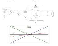
In long-term postponement due to personal circumstances.set up your bridge amplifier (symmetrical between rails) in the real world
Attachments
Class A is certainly not 'green', that's true.This enormous power loss
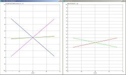
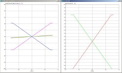
Simulated (!) responses with loads of 8, 4, 2 and 1 ohm.Let's take a look at the class A operation
Attachments
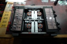
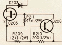
Fet's and BJT's have opposite tempco's (by Sony, in the 80's).Please explain in detail how the complete interconnection between the nodes q19_base and q18_base works.
Also what or who is thermally coupled to whom.
By the way, do you have enough components to select /and match them exactly and form pairs?
I do not prefer to select from oceans of components, as the industry does not either. The circuit design should cope with that.
The build in #126 consisted of a buy of 20 pairs, from which 4 pairs were deviating very much.
Attachments
Designed, simulated, not build, not tested (#79).are you absolutely sure that your design is actually mature, functional and practical
Attachments
absolutely right - thank you very much that I didn't have to openly state this fact myself.
However,
the published data on the ExtremA attest to unimaginable properties, literally "no longer measurable distortions or intermodulation ..."
You re welcome, as for Elektor statement that there s no mesurable THD + IMD it sound to me somewhat prepostperous,
class A and the EF3 help a lot but there s nothing in this design that would cancel any distorsion unless it has excessive
GNFB at high frequencies and is hence discutable stability wise.
One can design any possible circuitry it will be inherently limited by its two amplifying stages in this case, the intrinsical
non linearity of the transistors and the forcibly low NFB at 10-20kHz, there s no workaround for this limitation and increasing
the transistor count above the necessary one is just cosmetic.
Finally i get back to where i started, that is, the speakers wich have always orders of magnitude lower linearity than about
all amplifiers, you ll notice that Elektor never ventured in speakers design, and for a reason, all the difficulty is in this domain,
find a very good pair of speakers and suddenly all debates about amplifiers will appear for what they really are, an infinitesimality.
Keep in mind that this design configuration was conceived for another purpose, as stated in #87, last sentence.
As the lower circuit in #130 shows, the outputs are collector-collector nodes, and not stable without feedback.
That corresponds with NP's SUSY, but I've never encountered that design before mentioned in this topic.
Leaving the Sziklai's behind, low output impedance compounds (alike V-fet's) to replace them.
This development is on a more active pace the last few years and is taking considerable time, but publishment is unsure as publishers are not eager to adopt 'vacuum technology' in their portfolio.
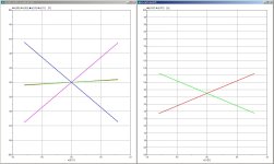
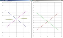
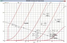
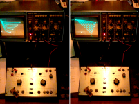
In the photo, the output characteristic of a standard (left) and modified (right) compound is shown (both flipped though).
As the lower circuit in #130 shows, the outputs are collector-collector nodes, and not stable without feedback.
That corresponds with NP's SUSY, but I've never encountered that design before mentioned in this topic.
Leaving the Sziklai's behind, low output impedance compounds (alike V-fet's) to replace them.
This development is on a more active pace the last few years and is taking considerable time, but publishment is unsure as publishers are not eager to adopt 'vacuum technology' in their portfolio.
In the photo, the output characteristic of a standard (left) and modified (right) compound is shown (both flipped though).
Attachments
So, did he ever?Unfortunately, he has not yet come up with a concrete circuit proposal, with component and dimensioning specifications.

Like in my case, with ear-speaker distance ~0.7m, 1 watt output already is loud. To enjoy "somewhat green" class A, one would have to start with a modulated current source with sufficient GNFB. When the reference voltage for the current source is derived from the supply voltage, lowering that lowers power and in such a way that at any given volltage the setting is optimal. My theoretical approach started (for a 2.5k output transformer) with this sim. The final and much improved version will be constructed probably end of this year.

I don't know that? But perhaps he dares to (now); however, the two opposing positions are also sufficiently outlined.So, did he ever?
My arms are wide open - this discussion pot is completely open and free from the liver. The rational person will (probably) lean towards Douglas Self's 20W-Blameless Class B design specification (the recipe). I would just be happy about a colorful discussion.
HBt.
Leaving the Sziklai's behind, low output impedance compounds (alike V-fet's) to replace them.
This development is on a more active pace the last few years and is taking considerable time, but publishment is unsure as publishers are not eager to adopt 'vacuum technology' in their portfolio.
I understand, well ...
Thanks for the nice pictures and maybe you can answer my questions later, but you don't have to - at the end it's not important.
kindly,
HBt.
A circuit diagram is already meaningful enough if the components are specified and dimensioned.
A flash of inspiration,
you originally wanted to build a compound power stage, an amplifier with the famous Sony Fets 2SK60 and the counterpart 2SJ18 and then you got stuck with a complementary Darlington replacement (NPN -> PNP, PNP -> NPN, and rotate or swap) due to the unavailability of these legendary unipolar transistors.
Say that right away.
And the X came about by chance because you wanted a bridge, so no Hiraga after all (no similarity either, unless you count a symmetry between the rails as similar or the same).
Everything can be quite simple if you /we communicate with each other correctly, I always say that to my wife - and express yourself /ourself correctly in language (or art).
Bye,
HBt.
you originally wanted to build a compound power stage, an amplifier with the famous Sony Fets 2SK60 and the counterpart 2SJ18 and then you got stuck with a complementary Darlington replacement (NPN -> PNP, PNP -> NPN, and rotate or swap) due to the unavailability of these legendary unipolar transistors.
Say that right away
.And the X came about by chance because you wanted a bridge, so no Hiraga after all (no similarity either, unless you count a symmetry between the rails as similar or the same).
Everything can be quite simple if you /we communicate with each other correctly, I always say that to my wife - and express yourself /ourself correctly in language (or art).
Bye,
HBt.
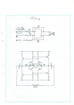
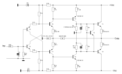
As a basis for discussion or as a gift for @cumbb, the Symm power amplifier by Helge Peters (published in Klang und Ton magazine 5/1991).
The lack of dimensioning is intentional, as the degrees of freedom can be very wide.
HBt.
The lack of dimensioning is intentional, as the degrees of freedom can be very wide.
HBt.
Attachments
I miss the discussion here about the sonic properties, or even the suitability for audio purposes, of circuits and concepts. We are in an audio forum, not one for amplifiers for "forest and meadow applications".
But I assume that we don't have the experience here to be able to assess designs in terms of sound.
I repeat, there is homework to be done! Basic research, science for audio, HiFi. So that audio and concepts don't just remain "Questions of faith"-)
But I assume that we don't have the experience here to be able to assess designs in terms of sound.
I repeat, there is homework to be done! Basic research, science for audio, HiFi. So that audio and concepts don't just remain "Questions of faith"-)
Make "double mono" power supplies. Connect these using cables and switches. And then listen, and occasionally switch the switch to connect or disconnect these channel-separated power supplies.
And take your time;-)
- Home
- Amplifiers
- Solid State
- Questions of faith - reflections on your own taste, thoughts about right or wrong!