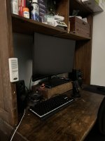
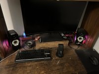
I like that idea but I’d only go down firing for a computer stand subwoofer and this sub seems too big for that. I built one before that sounded pretty good but was very low to the desk and it affected the sound too much. I do have a lot of space behind the monitor tho and I’m sure if I wall mounted it, it would sound good. If not then maybe a small sealed sub would work behind it like a Pioneer TS-A2000LD2 in its recommended sealed enclosure or something more efficient and ported or with prs. I’ll have pics of my old monitor stand sub and the space behind the screen where I can at max fit a 24x12x4 inch enclosure.
Attachments
Yes, I used used VitiuxCAD to simulate your design. I made a 3 way using the Dayton woofer and tweeter. I picked the Dayton PC68-8 as a mid range. The XO to build a 3 way will cost substantially more than the drivers you are picking. Honestly you should find a tweeter you can cross lower and build a 2 way.


Last edited:
Thank you for that. I came up with a new idea of using that tweeter or the Dayton Audio ND13FA-4 1/2" with the Dayton Audio RS100-4 4 in a two way x-over and pairing it with a small sub.
You would get 1 to 2 db less SPL at xmax with the 8 ohm version. The RS100's are going to reach xmax at about 16 watts, so you have way more power than you need.
I actually like the way the 4-ohm version models better and I was changing my design from the 8 ohm to the 4 ohm but have never gotten back to it. The only advantage of the 8 ohm is that I have a crossover that you can start with rather than starting from scratch. Do you have the tools to measure the drivers and design your own crossover? Because "off the shelf" crossovers, or those using online calculators, almost surely will not turn out good at all. Simulations from manufactured specifications may or may not turn out okay, there is no way to know.
Also, I don't know anyone who has used the ND13FA so can't comment on it, but the ND16FA-4 is known to be pretty good. I'd say the ND16FA-4
Here are two designs by well regarded designers. These have been heard at various DIY events and are known to sound good.
Small Batch using RS100P-4 (paper version) - https://projectgallery.parts-express.com/speaker-projects/the-small-batch/
Choti using RS100-4 - https://techtalk.parts-express.com/...micro-ht-speaker-using-the-rs100-4-and-nd16fa
Small Batch using RS100P-4 (paper version) - https://projectgallery.parts-express.com/speaker-projects/the-small-batch/
Choti using RS100-4 - https://techtalk.parts-express.com/...micro-ht-speaker-using-the-rs100-4-and-nd16fa

Here it is, please remember that this simulation won't necessarily match what you will build. Using factory data that was measured on an IEC baffle won't match what your enclosure will generate. This is just a proof that you chosen drivers might work. I'm crossing around 2khz, most likely to low, but for low SPL use it might be OK.


Using factory FRDs and ZMAs doesn't take into account box effects, edge diffraction, and the like. Based on this, inaccurate simulation results are obtained. The only thing worth doing is measuring the individual drivers in the actual box, then simulating, then tweaking until it sounds right. If you don't have measuring equipment, take some proven design.
Thank you for the help. I’m interested in this design here but I’m not sure how I’d copy it because me mentions that he did a lot of revisions and I don’t know how he made the final and all the parts he used.
First, I agree completely @NIXIE62 about the need to measure with the drivers in the enclosure. Next, don't worry about revisions, download VituixCad and add drivers in the drivers tab and import the FRD and ZMA files that can be downloaded from the Parts Express site for Dayton drivers. Then go to the crossover tab and build the XO's you see in my posts, then have fun. Next the ND25FA-4 has a nasty resonance peak the shows as a 4db peak at about 1.6khz which required the parallel notch filter in the tweeter circuit. The cost of these 3 components will cost more than the price difference between the ND25FA-4 and the DC28F-8. On top of that it will be a huge challenge fitting 12 components into you cabinet vs. 8 with the better tweeter.
Last edited:
The schematic in post #1 and diagram in post #19 are the final versions. He had something different originally in #1 but deleted it and replaced it with the updated version.Thank you for the help. I’m interested in this design here but I’m not sure how I’d copy it because me mentions that he did a lot of revisions and I don’t know how he made the final and all the parts he used.
- Home
- Loudspeakers
- Multi-Way
- First 3-way (crossover)