A thin layer of glue doesn't "break" the magnetic circuit.
Yeah, you can segment the curve as long as each row of magnets share the same pole piece.
Yeah, you can segment the curve as long as each row of magnets share the same pole piece.
Nice!
Apart from having to redesign it into smaller parts it might make it easier to manifacture. Since each segment is flat I won't have to curve which was something I was somewhat fearful of. I could also probably use the same dimensions of steel plate on the top and the bottom since I can fill in the gaps with the plastic parts. That would let me increase or decrease xmax or all the other dimensions without having to get new steel plates.
Assuming 7 cm wide plates:
7 rows 50x3x3 magnets
5 rows 50x3x3 magnets
3 rows 40x5x5 magnets
5 rows 12x5x3 magnets
5 rows 12x4x3 magnets
But because 12mm short segments might be overkill I might order 24mm long also / instead of 12mm long:
5 rows 24x5x3 magnets
5 rows 24x4x3 magnets
Since the main cost of laser cutting with fractory was the overhead I could probably order say 60cm of length of segments of each part for a reasonable price. Then I could play away with all the combinations and see what works best.
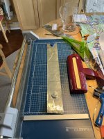
I bought the same corrugator you linked to in your thread @solhaga and it seems to work pretty well. It corrugates to roughly 1.5 mm peak to peak which is more than I'd like but by stretching the foil slightly I can turn it into 1 mm peak to peak. There is a risk, however, that the after-stretching will not be perfectly uniform so I might steam ahead with designing my own corrugaror. I bought some ball bearings with big enough inner diameter such that I can print the axles on my 3d printer without having to worry that it would snap.
I also learned that I will have to be careful when corrugating to ensure that it is corrugated perfectly parallel. I'll need to devise a technique to ensure that. One idea is to tape the membrane edge to a table and then stretch it while corrugating closer and closer to the taped edge. Or to build a feeding mechanism.
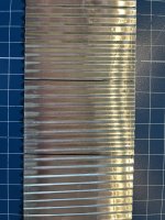
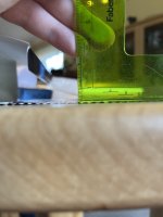
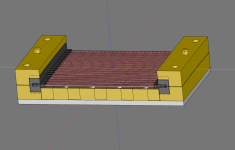
I also learned that I will need to property stretch the mylar before applying the aluminum foil. The membrane in the image looks like **** but it worked well enough to calculate how much length is lost from the corrugation.
The black lines are 5 cm long. With a 1.5 mm peak-to-peak it got reduced to 4.4 cm, when I stretched the peaks to to 1 mm it is reduced to 4.6 cm.
I also learned that I will have to be careful when corrugating to ensure that it is corrugated perfectly parallel. I'll need to devise a technique to ensure that. One idea is to tape the membrane edge to a table and then stretch it while corrugating closer and closer to the taped edge. Or to build a feeding mechanism.
I also learned that I will need to property stretch the mylar before applying the aluminum foil. The membrane in the image looks like **** but it worked well enough to calculate how much length is lost from the corrugation.
The black lines are 5 cm long. With a 1.5 mm peak-to-peak it got reduced to 4.4 cm, when I stretched the peaks to to 1 mm it is reduced to 4.6 cm.
Attachments
Last edited:
Yes, I've noticed that skewness too. My idea is to have guides that ensures the membrane to be fed straight.
Or I'll make my own as you are planning to. Here's some inspiration.
But I wonder if the precison of the coggs along the whole length of the corrugator will be better than the Uchida corrugator.
Have you got the Silhouette Cameo 5 yet?
I had to send mine back, when unpacking I discovered that the adjustable right roller was broken:


Too bad as this is the USP of this cutter. Appearantly the black Cameo 5 doesn't suffer from this weakness.
I guess the properties of the plastics are different; always use black zip ties you know.
Or I'll make my own as you are planning to. Here's some inspiration.
But I wonder if the precison of the coggs along the whole length of the corrugator will be better than the Uchida corrugator.
Have you got the Silhouette Cameo 5 yet?
I had to send mine back, when unpacking I discovered that the adjustable right roller was broken:
Too bad as this is the USP of this cutter. Appearantly the black Cameo 5 doesn't suffer from this weakness.
I guess the properties of the plastics are different; always use black zip ties you know.
I just dismantled the corrugator. I carved away some debris on the cogg endings and lubricated it all with silicone spray.
So now it rolls smoother and possibly straigther.
The thing does not have bearings, it's plastic against plastic, so I don't except to be a long term solution anyway.
It'll be very hard to keep a straight feeding of the membrane, in my case it is 230 cm long, holding the corrugator with left hand and cranking it with the right.
But, I think the cogg rolls can be repurposed. They are sturdy enough with a steel tube inside them and I also think it'll be hard to 3D-print anything sturdier and precise.
This is a very good idea, by the way, this will allow you not only to adjust the radius of the convexity, but also to create a reverse-focused driver, experiment will show everythingYou can even adjust the curvature of the speaker motor if you make hinges that connects the segment.
 .
.Nope, haven't received the Cameo 5 yet. I think I will this coming week.
Sucks that yours was broken, I hope you get a replacement as soon as possible!
And I guesstimate that as long as the 3d printed corrugator is designed to take account for any weaknesses due to printing (such as large inner diameter ball bearings to allow for large printed axles. Maybe also selectively print some parts with 100% infill like the axle + the teeth) then I think it will be strong enough to not be a problem. We are after all corrugating really thin mylar / kapton + some aluminum foil here, nothing really strong. And if we feel uncomfortable we could always just oversize it even more to compensate and make the corrugator stronger.
I think the problem will rather be the feeding mechanism, or rather how to ensure that the membrane is fed into the corrugator perfectly straight.
And while I could adjust the curvature of the speaker I don't think I will since I don't see the need for it. The 70 degree arc is chosen because matches the energy of a dipole radiation below the CBT cutoff frequency and thus interfaces nicely with the subs. Also, if I added hinges then that is more parts that blocks the sound making the response worse. Also unless the hinges were fixed in place then it would be additional parts that can rattle. But most importantly the difficult and costly parts to produce are the metal front and rear plates with the magnets glued on. If they are flat then the only parts with the curve are the 3d printed ones and those parts would be the cheapest and easiest to produce. So if I want to change the angle I could just re print them in any angle I want.
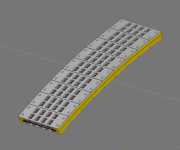
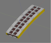
Drawings but with segmented steel plates.
The smaller is with 5 rows of 12x5x3 mm magnets. The bigger is 3 rows of 40x5x5 mm. More rows of smaller magnets are probably better but might as well try both
I also want to try with plastic pole pieces, will probably be worse but would be interesting to measure exactly how much worse. Will it just decrease efficiency or will it change the distortion specturm too?
If I order enough laser cut steel plates to cover ~ 50 cm of push pull drivers of:
5 rows: 12x5x3
5 rows: 12x4x3
7 rows: 50x3x3
3 rows: 40x5x5
It will only cost 204 € from fractory which isn't that bad. I'll wait a day or two, then re-check all my measurements and if all looks OK I'll probably send away an order for the parts.
If my magnet shipping estimates are correct I will get by first week of June so I want externally manifactured parts like the steel plates to have arrived by then.
Attachments
Last edited:

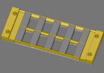
You are correct that if I go plastic I will probably need to get creative and add supports like this. I might need to add similar supports on the outside too.
I'm thinking if I can get away with 1.5 mm or if I should go 2 mm. They will not be as stiff as if they are curved and I don't have the tools to add flutes either. Maybe I should go thicker, but then the helmholtz resonance gets lower. It might be a good idea to add the plastic supports even on the steel plates. It will make everything slightly stiffer and also reduce the inner volume which will push up the resonance.
I'm thinking if I can get away with 1.5 mm or if I should go 2 mm. They will not be as stiff as if they are curved and I don't have the tools to add flutes either. Maybe I should go thicker, but then the helmholtz resonance gets lower. It might be a good idea to add the plastic supports even on the steel plates. It will make everything slightly stiffer and also reduce the inner volume which will push up the resonance.
Attachments
Last edited:
I made my parametric CAD model spit out the inputs to calculate helmholtz resonances:
5 rows of 5x3 mm magnets, 1.5 mm steel: 10300 hz
5 rows of 5x3 mm magnets, 2 mm steel: 9400 hz
3 rows of 5x5 mm magnets, 2mm steel: 7400 hz which makes sense since the magnets are much taller.
5 rows of 5x5 mm magnets, 2mm steel: 7200 hz.
I guess the thicker magnets would make sense if I go 5 rows but skip push-pull and instead go single-ended. A 7200 hz resonance on the rear should not be a problem. Might be worth testing.
Last edited:
Rear os more or less = front - no?
As in that they are symmetric? In the push-pull case absolutely.
But I could try SE in which case it won't. The frequency response should then be far smoother on the front. The distortion, however, will be far worse but the question is how much worse. I don't like lots of 3rd order distortion so I don't plan to truly push the drivers such that they start to distort. I'd rather just cross higher to avoid the distortion peak.
And in that case then while SE will distort more, it might still be good enough.
Attachments
- Home
- Loudspeakers
- Planars & Exotics
- DIY midtweeter planar, physically curved and shaded to be used in a dipole CBT