We have been developing a digitally-controlled precision LDR-based preamp for the last four years.
It's finally a mature design that includes a variety of control options and a very nice OLED display in addition to very precise control of the LDRs, and we're making it available on our website at BTFSystems, and answering non-commercial technical questions at our ongoing diyaudio thread here
You'll find lots of information about the development phase on diyaudio, and more photos and current information on the website.
Last edited:
Great...you now have a shopping cart on your site.
So what all is required for a remote-controlled system with a OLED display, items 1,2 and 4?
Are any special cables like ribbon cables required?
Great questions, I'm going to incorporate this information in the website as soon as I can.
For the complete, all-capabilities-included system you describe, you need all four components - the LDR controller, the RE/IR/Display Controller, the rotary encoder to control the system, and the OLED display to give you status information. (But feel free to use your own rotary encoder if desired.)
However, there are three ways to configure these components with increasing convenience and elegance. For all configurations the quality of the LDR sound does not change, you always get that LDR sound quality.
1. The simplest -- LDR controller board only:
If you want the LDR sound with tight digital control at minimum cost, you need just the LDR controller board which comes with a simple status LED. You supply two 10K linear potentiometers (any quality) for Volume and Balance control, feed it DC power at 9~16VDC, and connect your audio cables. It's that easy.
The LED included with the LDR Controller has a variety of flash patterns and rates that give you adequate information for calibration in process and complete, and indicates when Balance is changing (i.e., you're moving the pot) and when Balance is exactly centered, and when sound is Muted.
Turning the volume control fully CCW will mute the audio so you don't need a Mute switch, on the other hand a separate Mute switch can easily be added to the volume control circuit.
2. Adding infrared remote capability and rotary-encoder control -- the RE/IR/Display Controller:
This controller gives you control of all functions from a single rotary encoder knob, and control of your system (Volume, Balance, Mute) from your listening position using any IR remote programmed with Sony-compatible TV/VCR codes. There's a huge variety of compatible remotes out there; I bought mine new online for $5.50 delivered.
The simple LED can be attached to this board and provides much the same information as when connected to the LDR controller board.
You do need a rotary encoder control to operate this board. It is sold separately so that if you don't want or need the direct-match screw-terminal convenience, you can use your own control.
The requirement for the encoder is because it is impractical to have IR control and simple pots work together -- you would quickly have the IR control commanding a different volume level from the manually-controlled pots, and this would be unworkable. IR control with pots would require the pots to be motorized to track with the IR-commanded levels.
3. Add the OLED Display to the RE/IR/Display board:
The OLED display is optional, but adds a lot of convenience and panache to the system. You get a visual indication of the Volume level which is easily readable across the room, plus Balance offset, flashing Mute, and current flowing through the shunt LDRs, and Calibration status in percentage complete. The Display comes with a push-on 3-conductor wire which makes it plug-and-play with the controller board.
Other than the Display cable which is included and also available at any store selling RC hobby equipment, there are no special cables required.
The only critical wiring is the audio wiring where you follow standard practice, like staying away from power wiring, etc. All connections except for the OLED cable are single wire connections to screw terminals.
Please ask any other questions you might have!
Great...you now have a shopping cart on your site.
So what all is required for a remote-controlled system with a OLED display, items 1,2 and 4?
Are any special cables like ribbon cables required?
I have added the answers to your questions to the website, thanks for asking.
2. Adding infrared remote capability and rotary-encoder control -- the RE/IR/Display Controller:
This controller gives you control of all functions from a single rotary encoder knob, and control of your system (Volume, Balance, Mute) from your listening position using any IR remote programmed with Sony-compatible TV/VCR codes. There's a huge variety of compatible remotes out there; I bought mine new online for $5.50 delivered.
The simple LED can be attached to this board and provides much the same information as when connected to the LDR controller board.
You do need a rotary encoder control to operate this board. It is sold separately so that if you don't want or need the direct-match screw-terminal convenience, you can use your own control.
The requirement for the encoder is because it is impractical to have IR control and simple pots work together -- you would quickly have the IR control commanding a different volume level from the manually-controlled pots, and this would be unworkable. IR control with pots would require the pots to be motorized to track with the IR-commanded levels.
I'm a little confused about this option that uses a encoder along with remote control capability.
If you can use the remote to control volume, balance, etc., why the need for the encoder?
Does the encoder select the mode(like volume or balance), perhaps by pushing it in, so the remote will control that mode?
The remote is to control Volume/Balance/Mute from a distance. The encoder is used when standing in front of the front panel. It replaces the Volume and Balance pots and mute switch. It also switches the LDR current display from auto-on-above-5ma to always-on.
Your front panel would consist of only the single rotary encoder knob and the display, or the single rotary encoder and a simple LED to determine status. The IR receiver would have to be behind a hole in the front panel or share the plexiglas window that covers the display.
Hi
Couple of questions. Do you have plans to develop an input swiching function to enable multiple inputs and if so, how easy would it be to add it to a working unit at a later date?
Also, rereading back through the thread, still not sure on this one; does the RE/IR/Display Controller board have a dual H-bridge chip onboard to control power to a motorized pot?
If not, what would be needed to get a motorized pot working?
Thanks
Hi
Couple of questions. Do you have plans to develop an input swiching function to enable multiple inputs and if so, how easy would it be to add it to a working unit at a later date?
Also, rereading back through the thread, still not sure on this one; does the RE/IR/Display Controller board have a dual H-bridge chip onboard to control power to a motorized pot?
If not, what would be needed to get a motorized pot working?
Thanks
1. Plans for input switching function -- yes, I plan to do that, and using pure LDR control if at all possible.
2. The RE/IR/Display board works only with a rotary encoder -- the "RE" part of the name. There is no H-bridge on this board.
3. I've already built a prototype motorized pot front end (see attached image of my prototy[e). The design is two years old, I'd do it differently now but the concept is there, and it worked just fine. The balance could also be motorized if you wanted it to be -- the H bridge chip I used will handle two motors.
I switched to rotary encoder because the opinion on the thread at the time preferred it to motorized pots. I can see this as a way to upgrade an existing amplifier, but starting from scratch an encoder might be a better choice.
If there's enough interest I can make a motorized pot front end happen . . .
Attachments
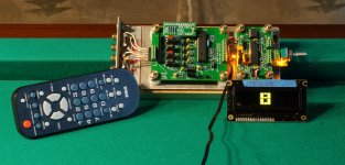
Someone asked about how difficult the wiring would be, the answer is: "dead simple."
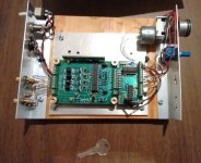
This image is of my test rig -- the complete system with rotary encoder and IR receiver and OLED display connected to the LDR controller module.
The LDR controller module wiring consists of the connections to the audio jacks at one end, and +12VDC and two wires to the RE/IR/Display board at the other end.
The RE/IR/Display board connections are to the LDR board and +12VDC on one side, and the IR receiver (barely visible above the rotary encoder) and rotary encoder on the other side, plus the plug-in OLED cable.
That's it.
The LEDs are inserted for testing, they are not required when the OLED display is connected.
The remote controller is an inexpensive generic universal controller which does what's needed -- volume, balance, mute.
Attachments
Last edited:
The wiring does look about as simple as simple gets.
So where the wall wart connects to the LDR controller board, you also have 2 wires coming out of that board(in parallel with the wall wart wires) going to the "9-16VDC" connections on the RE/IR board to power it?
I also see the 2 wires near the top for the +12VDC connection.
Just as a suggestion...you may want to take some close up photos of the wiring connections on your test rig for those who still may be unsure or have questions.
Does your setup come with instructions on identifying the LED's pulses or flashes for those who don't get the OLED display?
Why is shipping $15 whether someone purchases an encoder only or the entire 4-piece setup?
I was hoping to get the LDR module initially, then maybe upgrade to the RE/IR board/encoder at a later date and maybe the display at even a later date.
But if I'm going to be hit with a $15 shipping charge each time, then upgrading is out of the question for me as I can't afford $45 in shipping charges.
The wiring does look about as simple as simple gets.
So where the wall wart connects to the LDR controller board, you also have 2 wires coming out of that board(in parallel with the wall wart wires) going to the "9-16VDC" connections on the RE/IR board to power it?
I also see the 2 wires near the top for the +12VDC connection.
Just as a suggestion...you may want to take some close up photos of the wiring connections on your test rig for those who still may be unsure or have questions.
Does your setup come with instructions on identifying the LED's pulses or flashes for those who don't get the OLED display?
I will be putting together a straightforward set of instructions in the next few days, that's in the works to support the early adopters whose kits are already in the mail.
Why is shipping $15 whether someone purchases an encoder only or the entire 4-piece setup?
I was hoping to get the LDR module initially, then maybe upgrade to the RE/IR board/encoder at a later date and maybe the display at even a later date.
But if I'm going to be hit with a $15 shipping charge each time, then upgrading is out of the question for me as I can't afford $45 in shipping charges.
You make a valid point in your situation. The same difficulty applies to everyone and to other countries where shipping with insurance comes to $25 per shipment or even $65 per shipment, depending on the country.
Everyone has a different perspective and I have one too: Of that $15, depending on the contents, the cost of insurance alone can be more than $5.00 and the total cost of shipping exceeds $15 and I lose money. It is my attempt to find an overall fair price that doesn't have me spending a lot of my time doing things like weighing individual packages and putting different amounts of postage on each one which would kill my enthusiasm and thus kill my fledgling business.
Having one shipping price and having the small overcost and undercosts average out is a good and convenient system. I hope you will understand if I don't change my business model to accomodate your desire to piecemeal your acquisition.
Personally, I would decide what I want/need and can afford, and order it in one go because this is very fairly priced stuff considering the capabilities, and keeping the cost of shipping to a minimum is to the buyer's advantage.
Do the 10K pots need to be dual or single?
Single. Remember, you're just changing a control voltage, not the audio signal. You need one each for Volume and Balance.
Also remember that quality is not important as long as it's reasonable.
I uploaded two wiring diagrams to the BTFSystems website -- one shows the most basic circuit using 10K linear potentiometers and the LDR Controller, the other shows the wiring for the complete system to include the RE/IR/Display Controller board and circuitry.
The standout feature -- both systems are extremely easy to wire up.
Also uploaded the complete calibration procedure using either the OLED Display or a simple LED indicator. Also very easy, and very seldom required.
The standout feature -- both systems are extremely easy to wire up.
Also uploaded the complete calibration procedure using either the OLED Display or a simple LED indicator. Also very easy, and very seldom required.
In this drawing, are the pots' terminals up or down?
In a simple circuit where the pot is controlling the input of a audio signal(I know we are controlling voltages here instead) with the terminals facing down like on a PCB, the terminals you have labeled as Max. are typically grounded and the terminals you have labeled Min. are where the audio enters the pot.
In a simple circuit where the pot is controlling the input of a audio signal(I know we are controlling voltages here instead) with the terminals facing down like on a PCB, the terminals you have labeled as Max. are typically grounded and the terminals you have labeled Min. are where the audio enters the pot.
Attachments
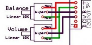
Oops! I had a look at mine and it's connected as per the diagram with the +5 volt connection to the pins adjacent to the 'max' label as you look at them from 'on top' position - initially, I had them connected incorrectly (the other way) and simply changed the wires at the terminal block instead of changing the wires on the pots - same thing for the balance pot
- Status
- This old topic is closed. If you want to reopen this topic, contact a moderator using the "Report Post" button.
- Home
- Vendor's Bazaar
- BTFSystems precisionLDR modules for digitally-controlled LDR Passive Preamp