I think there is a good argument to go even further and run the power amp at unity gain.
From a signal integrity standpoint, that's certainly true. Sadly, the number of available opamps drop precipitously once you push beyond ±18 V and to near zero for ±20 V rails.
But that is outside of this topic and needs beer!
I can open a bottle but the cool thing would be to share the conversation and beers at the same physical place, right? 😎
Perhaps the three of us could get together next time I'm in EU Land. 🙂
Tom
Perhaps the three of us could get together next time I'm in EU Land. 🙂
Tom
You have paid beers whenever you come to Barcelona.
Surely overlooked due to the beer conversation, but could you have a look at correction and question in post 117 from previous page re gain? 🙄
I will assume as well that all gain in the board is provided by the THAT1646, no gain from the opamps, right?
Correct. And you can't place a volume control between the two without cutting traces on the board. I also don't think you'd want to. The opamp is there to drive the somewhat low input impedance of the THAT1646 (and to provide gain for those who need it).
Tom
Correct. And you can't place a volume control between the two without cutting traces on the board. I also don't think you'd want to. The opamp is there to drive the somewhat low input impedance of the THAT1646 (and to provide gain for those who need it).
Tom
Thank you for confirmation. I will need a gain stage before the THAT driver then, maybe just another 6dB
Tom
I already have a dual 15 volt regulated power supply. I assume there is no way to use this???
Mike
I already have a dual 15 volt regulated power supply. I assume there is no way to use this???
Mike
I was just wondering the same thing. There is a J6 header with +/- 15V pins. Can we connect power there after the regulators?
Sure. Just don't populate the regulators and associated components and hook your clean ±15 V supply at J6.
Tom
Tom
Correct. And you can't place a volume control between the two without cutting traces on the board. I also don't think you'd want to. The opamp is there to drive the somewhat low input impedance of the THAT1646 (and to provide gain for those who need it).
Tom
Thank you for confirmation. I will need a gain stage before the THAT driver then, maybe just another 6dB
OK, I'm reading a lot on opamps these days, but I think I suffer over-information panic. Too much info for my electronics uneducated brain. If I want to have a clean, low distortion gain before the volume before the THAT Driver, what easy design can I use? Basic diagram below:
[DAC 1.2VRMS 600Zout SE > I/V > (3-6dB gain) > attenuator/pot > THAT Driver] XLR cable [Mod86 power amp]
Thank you
The THAT Driver has 6 dB gain already, so I'd start with:
DAC -> Volume Control -> THAT Driver -> MOD86.
If you need more gain, I'd use the input buffer/gain stage on the THAT Driver to boost the gain. You can do that by changing a resistor. I give the values in the design doc.
You are correct that a better place for the gain would be before the volume control, but for 3-6 dB gain, I'm not overly concerned about putting it after. If you insist on putting it before the volume control, I suggest putting an LME49720 with the appropriate decoupling capacitors and gain setting resistors on a piece of prototype board and build yourself a little gain stage. You can power it from the ±15 V of the THAT Driver. In that case the block diagram becomes:
DAC -> Gain stage -> Volume control -> THAT Driver -> MOD86
Tom
The THAT Driver has 6 dB gain already, so I'd start with:
DAC -> Volume Control -> THAT Driver -> MOD86.
If you need more gain, I'd use the input buffer/gain stage on the THAT Driver to boost the gain. You can do that by changing a resistor. I give the values in the design doc.
You are correct that a better place for the gain would be before the volume control, but for 3-6 dB gain, I'm not overly concerned about putting it after. If you insist on putting it before the volume control, I suggest putting an LME49720 with the appropriate decoupling capacitors and gain setting resistors on a piece of prototype board and build yourself a little gain stage. You can power it from the ±15 V of the THAT Driver. In that case the block diagram becomes:
DAC -> Gain stage -> Volume control -> THAT Driver -> MOD86
Tom
i gotta love you man!
Hey Tom,
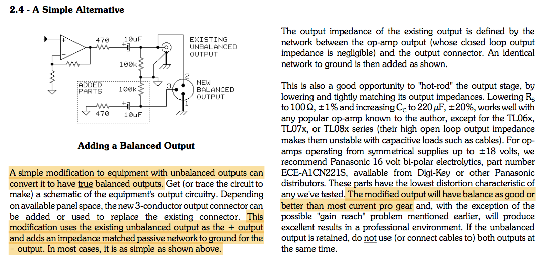
One extra question. Are you aware of the unbalanced to balanced interface proposed at Jensen AN-003 figure 2.4? It uses only a pair of resistors and a cap, no transformers involved.
How do you see that in comparison to the Pseudo-Differential cable?
Thank you
One extra question. Are you aware of the unbalanced to balanced interface proposed at Jensen AN-003 figure 2.4? It uses only a pair of resistors and a cap, no transformers involved.
How do you see that in comparison to the Pseudo-Differential cable?
Thank you
Attachments

Interestingly, I was in a similar discussion over on ASR not long ago. Some argue that balanced is not the same as differential. They'd be in Whitlock's camp (Whitlock is the guy who wrote Jensen AN-003). While I do understand where they're coming from, I don't understand their justification for the discussion. Here're my thoughts:
In a single-ended system, the "ground" conductor is part of the signal path, thus, any ground current will introduce an error signal which is added to the desired signal. Using differential signalling prevents this by moving the ground outside the signal path.
A well-designed differential system is fully balanced. Deliberately introducing an imbalance wrecks performance, thus, I find it negligent to do so. That's also why I've been using the terms "differential" and "balanced" interchangeably. Perhaps that's my mistake. 🙂
As shown in Whitlock's app note, it is possible to have a circuit that is balanced but not differential. Whitlock claims that in this configuration, you still get the benefit of the CMRR of the differential input. That's true as long as the input common-mode impedance is high. If the CM input impedance is low, you start having an error current flowing in the (-) signal lead and now you're essentially back to a single-ended system.
One way to get high CM impedance is to use a transformer, which Whitlock shows further down in the app note. Another way is to bootstrap the input common-mode voltage as Whitlock does in his patent (licensed by THAT Corp for the THAT1200).
How does Fig. 2.4 above compare with a pseudo-differential cable? Let Rs (470 Ω) go to zero and Cc (100 uF) go to infinity and you have a pseudo-differential cable connection. Or perhaps, I should call it a pseudo-balanced cable connection... 🙂 Now you just wrecked the CM impedance (i.e. drove it to 0 Ω by having Rs go to 0 Ω), thus, if you have any imbalance in the impedances of the signal pair (which you do as one is grounded and the other driven by an opamp), you won't get any CMRR.
The balanced output shown in Fig. 2.4 will work well as long as the impedances are actually balanced. This means the performance of the circuit will depend on the matching between the two (Rs+Cc)s. If you choose ±1 % tolerance resistors and ±5 % (or ±1 %) tolerance caps, you can probably make it work reasonably well. I bet a well-designed differential driver will still work better.
So: THAT Driver differential output > Balanced output > pseudo-differential cable
That's my analysis. I'm looking forward to the discussion.
Tom
The circuit shown is common. It's often used in condenser microphones with solid-state circuitry and no output transformer. As far as I know, the claim to fame is that it makes possible CMR at the preamp for any signal (almost always common-mode) picked up by a long microphone cable. It's not the best way of doing things, but better than not doing it.
It's not the best way of doing things, but better than not doing it.
I like that summary.
Tom
My THAT driver kit should be arriving soon (thanks Tom). I hope I bought it for the right reason. It's my understanding the most amplifiers with differential/balanced inputs have circuitry to convert the differential signals back to se, then feed that signal into one amplifier. The circuitry removes noise prior to the amplification.
I have a TPA3255EVM. In BTL mode, it creates differential signals from se inputs using inverting op amps. With differential signals, I can bypass these op amps. Each differential signal would then pass through a 10uf cap and straight to the chip's inputs.
The THAT driver preamp would provide these benefits...
1) Eliminate noise from the se source.
2) Have a high enough input impedance to allow for a 10K potentiometer on
the se inputs.
3) Allow me to bypass the op amps and go straight to the 10 uf cap/chip
inputs.
4) Any noise picked up after the THAT 1646 would be cancelled out at BTL
connected speaker, since the music signal is inverted on the negative side
of the speaker, but the noise picked up on both the inverted and non-
inverted signals is equal. In other words, the speaker itself "rejects" the
noise common to the inverted and non-inverted signals.
Does this sound right?
Mike
A well-designed differential system is fully balanced. Deliberately introducing an imbalance wrecks performance, thus, I find it negligent to do so.
The balanced output shown in Fig. 2.4 will work well as long as the impedances are actually balanced. This means the performance of the circuit will depend on the matching between the two (Rs+Cc)s.
So: THAT Driver differential output > Balanced output > pseudo-differential cable
That's my analysis. I'm looking forward to the discussion.
Tom
It's not the best way of doing things, but better than not doing it.
Given Tom and Brian's answers above, I'd say it is really worth it and there is a right reason to go balanced through the THAT driver in comparison to the Jensen AN-003 approach. I actually didn't imply the THAT driver was not needed, it was more a theoretical question to try to understand the science behind that approach compared to the usual pseudo-solution Tom gives with the Pseudo-Differential cable.I hope I bought it for the right reason.
Thank you guys
Another comment on this. In the pro audio world virtually all microphone cable runs are 'balanced' with 2-conductor shielded cable. The microphone makers can save a few pennies by not creating a true differential source at the mic. In the case of very small mics, there may not be the space for added circuitry. Thus this band-aid approach is not uncommon.
The circuitry removes noise prior to the amplification.
That's a bit of a stretch. The THAT Driver and THAT Receiver cannot distinguish between noise and signal if either of these are applied to their inputs. There is no noise cancellation or error correction applied here.
The benefit of using the differential link is that the ground connection is moved outside of the signal path, thus, any ground-induced noise (for example from ground loops) will not corrupt the signal. Another benefit is that any noise coupled evenly to each conductor in the differential pair will be attenuated by the CMRR (typ. 90+ dB) which makes differential links much less sensitive to mains hum and other sources of EMI. Finally, the THAT Driver and THAT Receiver contain RFI filters and ESD protection, which reduces the impact of RF interference and allows the circuits to be hot-plugged (i.e. connected to with the power on).
I have a TPA3255EVM. In BTL mode, it creates differential signals from se inputs using inverting op amps. With differential signals, I can bypass these op amps. Each differential signal would then pass through a 10uf cap and straight to the chip's inputs.
That sounds right.
1) Eliminate noise from the se source.
Nope. Any noise from the source will be treated as signal.
2) Have a high enough input impedance to allow for a 10K potentiometer on the se inputs.
Yep.
3) Allow me to bypass the op amps and go straight to the 10 uf cap/chip inputs.
Yep. You can connect the THAT Driver directly at J26 and J27 of the TPA3255EVM. That will provide the EVM with a single-ended input with an input impedance of 100 kΩ - high enough that you can connect a volume pot up front.
4) Any noise picked up after the THAT 1646 would be cancelled out at BTL connected speaker, since the music signal is inverted on the negative side of the speaker, but the noise picked up on both the inverted and non-inverted signals is equal. In other words, the speaker itself "rejects" the noise common to the inverted and non-inverted signals.
If the two halves of the TPA... are symmetrical, any error introduced equally to each half will be canceled at the speaker. In reality, no cancellation is ever perfect, but in theory it works that way.
Tom
Last edited:
- Home
- Vendor's Bazaar
- THAT Driver :: A minimalistic differential driver / preamp with 0.000021 % THD