Tom, I have some good news. The GBPC2510 / KBPC2510 bridge rectifier that you plan to use (see post#205) appears to be a medium-to-low capacitance device: 146pF @ zero bias, according to the spice model provided by Diodes Inc, and 435pF @ zero bias, according to the spice model provided by Vishay. As a further double-check, the 35 ampere bridge rectifier spice model on the Cordell Audio website, says 500pF @ zero bias.
This is good news, because the diode capacitance is comfortably below (in fact way below) the 3300pF Cx value of the Modulus Toroid Universal CRC Snubber described in post#408. As desired, Cx >> Crectifier and so the snubber performance (damping factor) will not be affected by variations in Crectifier.
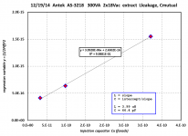
Although I don't have an example of the Antek AS-2222 (200VA, 2x22 Vac) toroid that you recommend, I do have its big brother: the Antek AS-3218 (300VA, 2x18 Vac). It's shielded, same as the AS-2222. I measured it today and found that the secondary winding capacitance is nice and small: just 66 pF (measurement attached below). This is also good news because it means that unit-to-unit variation in secondary winding capacitance ("mutual capacitance") will not affect snubber performance. Cx >> (Crectifier + Csecondary). Throw in another 0-200 pF for the secondary hook-up wires, the secondary fuseholders, and PCB traces; you still get Cx >> (Crectifier + Csecondary + Cwiring). Big Cx has rendered the snubber performance insensitive to variations in the diode capacitance, the transformer capacitance, and the amplifier hookup wiring capacitance.
So it's looking better and better for the Modulus Toroid Universal CRC snubber: Cx = 3.3nF stacked film; Rx = 22 ohms; Cs >= 680nF stacked film.
_
This is good news, because the diode capacitance is comfortably below (in fact way below) the 3300pF Cx value of the Modulus Toroid Universal CRC Snubber described in post#408. As desired, Cx >> Crectifier and so the snubber performance (damping factor) will not be affected by variations in Crectifier.
Although I don't have an example of the Antek AS-2222 (200VA, 2x22 Vac) toroid that you recommend, I do have its big brother: the Antek AS-3218 (300VA, 2x18 Vac). It's shielded, same as the AS-2222. I measured it today and found that the secondary winding capacitance is nice and small: just 66 pF (measurement attached below). This is also good news because it means that unit-to-unit variation in secondary winding capacitance ("mutual capacitance") will not affect snubber performance. Cx >> (Crectifier + Csecondary). Throw in another 0-200 pF for the secondary hook-up wires, the secondary fuseholders, and PCB traces; you still get Cx >> (Crectifier + Csecondary + Cwiring). Big Cx has rendered the snubber performance insensitive to variations in the diode capacitance, the transformer capacitance, and the amplifier hookup wiring capacitance.
So it's looking better and better for the Modulus Toroid Universal CRC snubber: Cx = 3.3nF stacked film; Rx = 22 ohms; Cs >= 680nF stacked film.
_
Attachments
Fair cop. I did a poor job of trying to make a point, which is that compression causes a "different" type of distortion. However, the upside is that you gave a perfect example of how to expose weaknesses in a reproduction system - which is to feed it a signal which makes aberrations glaringly obvious - which the standard, steady state testing of audio does not do.You have obviously never tried measuring MP3 distortion. It's huge and very obvious, both in frequency domain and time domain measurements. Try MP3 compressing a 1kHz square wave, uncompressing it again, and comparing the waveform to the original.
The principle remains the same. If the subjective impression is that the system is not working correctly, then determine what method of testing exposes the defect to the bright light of day - do not blindly keep applying the same old, convenient method of measuring, which barely hints as to there being an issue ...
Mark, I appreciate the data and your calculations. The Power-86 board will have a capacitor across the transformer secondaries (one cap per secondary). I will leave it up to the builders to add more complicated snubbing schemes as they see fit. Personally, I don't see any technical need for this as none of the ringing on the diodes ever makes it even to the output of the power supply and its frequency is too low to couple into anything with any appreciable efficiency. None of the ringing is present on the amp output. If someone asks, I'll be happy to suggest your values as a starting point.
~Tom
~Tom
The principle remains the same. If the subjective impression is that the system iI'm not working correctly, then determine what method of testing exposes the defect to the bright light of day - do not blindly keep applying the same old, convenient method of measuring, which barely hints as to there being an issue ...
Any time I felt something was wrong with the sound of an audio system, I've always investigated it with measurements. I've always found some obvious objective defect that explains the bad sound. A loose connection giving 0.5% THD, or a funky speaker design with a huge dip in output at the crossover frequency, or cheap ceramic capacitors in an active filter that should have had precision film caps.
Of course this opens me to the accusation that my pinnae are just not sufficiently golden. Well fine. I'm glad that I'm not cursed with the ability to hear the brand and date code of every opamp the signal passed through on its way through the studio. (Or the difference between a Modulus-86 and a regular chip amp
") )
)Tom, I don't think that's the best decision. I think your customers would be best served by placing a CRC snubber across each secondary, at least in the PCB layout. Then you have the option of recommending that Cx1 = Cx2 = 100nF is your preferred design, while Cs1, Cs2, Rs1, Rs2 are optional -- and you suggest omitting them.The Power-86 board will have a capacitor across the transformer secondaries (one cap per secondary). I will leave it up to the builders to add more complicated snubbing schemes as they see fit.
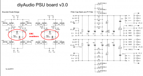
This is the approach taken on the diyAudio Universal Power Supply circuit boards sold here in the The diyAudio Store. CRC snubbers are provided in the PCB layout (red circles below); however, it is left as an option for the buyer/builder, whether or not to populate them. It is also left to the buyer/builder to choose component values and to purchase them. (discussion thread) . I've included its schematic, below.
This has worked well, even though Universal Power Supply board buyers often don't own oscilloscopes, pulse generators, or other test equipment. But the idea of oscilloscope-less people building a snubbered power supply seems to make you nervous; in post 406 you say " ... optimizing the snubber. However, this requires that each builder has the skill and equipment to perform the optimization. Each build would have to be optimized separately as the parasitic inductance and capacitance of the transformer, wiring, etc. vary from build to build."
I think you're too worried; DIYA Universal Power Supply board buyers have navigated these waters successfully, and so can Modulus Power Supply board buyers. Besides, your board has an unfair advantage: the Modulus PS board is not trying to be universal! You are more or less guaranteed that it'll be driven by a transformer rated between 100VA and 400VA, with secondaries rated between 12VAC and 25VAC. This puts limits on the min possible and max possible secondary leakage inductance, which is the only important variable. All other variables are rendered insignificant, since they are swamped out by using a CRC snubber with large (3.3nF) Cx. Parasitic capacitance of the transformer? Insignificant! Wiring capacitance of the builder's chassis & boards? Insignificant! Junction capacitance of the rectifiers (and its variation with bias voltage)? Insignificant!
You only need to design a CRC snubber to handle a small range of secondary leakage inductance: 100-to-1, or less. This translates to an even smaller range (square root of 100-to-1) of damping factors. By judicious choice of the bottom and top ends of the range, you can provide a single CRC snubber that completely eliminates (damps) all ringing in all Modulus transformers.
Don't underestimate the pleasure and relief that people will get from eliminating that 67 kHz oscillation, the one you deem harmless. Get this %#%#%# the hell OUT of my amplifier! (they will say). Especially when the cost is only two resistors and two capacitors, many people will say they don't care whether or not that oscillation is harmless, they want it removed anyway. Killed. Snubbed to death, and the quicker the better.
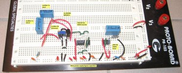
I suspect that a few Modulus builders have spent the 1.5 hours necessary to construct a Quasimodo test-jig on their solderless breadboard (picture below). I suspect they will hook it up to their Modulus transformer and upload the before-and-after waveform photos to this very thread. I further suspect that the resounding replies will be "Holy Moly! Do you mean to tell me that those nasty RF sinusoids are running around in my amplifier! And I can totally wipe them out with just two resistors and two capacitors? Sign me up!"
_
Attachments
Last edited:
IME the problems are more, say, in the areas of under-engineered power supplies, or excessive sensitivity to external interference - the audible effects are of a different nature to what many would be looking for ... once the characteristics are "tuned into" then it becomes easy to pick the behaviour ...Any time I felt something was wrong with the sound of an audio system, I've always investigated it with measurements. I've always found some obvious objective defect that explains the bad sound. A loose connection giving 0.5% THD, or a funky speaker design with a huge dip in output at the crossover frequency, or cheap ceramic capacitors in an active filter that should have had precision film caps.
Of course this opens me to the accusation that my pinnae are just not sufficiently golden. Well fine. I'm glad that I'm not cursed with the ability to hear the brand and date code of every opamp the signal passed through on its way through the studio. (Or the difference between a Modulus-86 and a regular chip amp
Last edited:
A Faraday shield in a transformer is an extension of the Faraday cage formed by the chassis. You are trying to make it so the primary is outside the cage and the secondaries are inside. So ideally the Faraday shield should be connected to the chassis by a short low impedance path.
However, the Faraday shield unavoidably has some inductance of its own (a hole in it if you like) as it can't be allowed to form a shorted turn. The Faraday shields in the Airlink toroids are made by wrapping multiple turns of insulated copper foil, so they probably have far more inductance than the connecting lead and won't do much at really high frequencies.
I think there is some confusion here (at least in my mind). Airlink offer 2 types of shielding.
1. Electrostatic/Faraday between primary and secondary which you refer to above which Airlink say is connected to ground, but nothing about if it has a seperate lead for this (annoying as will have to buy one to find out)
2. EMI/RF STEEL bands around the whole transformer, which they appear to suggest is connected to nothing. Again annoying as floating steel is what i would call an antenna rather than a shield.
In an ideal world these would both be connected to a post on the chassis where the incoming earth is terminated. As I understand Tom's PS board is a few mOhms from optimal, but close enough to ensure anyone can make this work.
Based on measurements not sure either is required for this amplifier to obtain pretty much SOTA performance. We are not producing a satellite/missile/helicopter/airbag controller (delete according to your own day job EMC nightmare). As I said before i am going to use a plurality of these as my reference for many years (decades overdue end to end system upgrate), so for me pushing the law of diminishing returns is worthwhile even if a lash up with whatever was lying around would sound just as good.
Toroids with interwinding screens that I've encountered do bring the connection out (normally a green or green/yellow wire) for connecting to chassis. The steel band (which is intended to reduce stray flux) I'd not bother with on a toroid - their radiated flux is low, worst at the discontinuity where the lead-out wires are. So turn the trafo so the lead-outs face directly away from sensitive circuits.
I think your customers would be best served by placing a CRC snubber across each secondary, at least in the PCB layout.
In my view you are trying to solve a non-issue. I have no intention to force my customer to pay extra to get something they don't need. If there was a problem, I would address it. But there is no problem. There is nothing for me to solve here.
This is the approach taken on the diyAudio Universal Power Supply circuit boards sold here in the The diyAudio Store.
That's fantastic. Those who wish to have the footprints available for a CRC snubber are free to buy those boards. They can also solder the two additional components onto the bottom of my board.
CRC snubbers are provided in the PCB layout (red circles below); however, it is left as an option for the buyer/builder, whether or not to populate them.
Those options cost money. They cost board area, component cost, documentation, testing, etc. All that to achieve absolutely nothing. There will be no measurable difference on the output of the amp. I have verified this already. Any perceived sound quality difference obtained by more complicated snubbers are in my opinion caused by confirmation bias and other psycho-acoustic effects.
I think I have made it rather clear in this thread several times: I base my design decisions on engineering and data. Not religion. Others are free to disagree.
IME the problems are more, say, in the areas of under-engineered power supplies, or excessive sensitivity to external interference - the audible effects are of a different nature to what many would be looking for ... once the characteristics are "tuned into" then it becomes easy to pick the behaviour ...
I bet most issues are in the amplifier circuit itself. Many designs have rather poor supply rejection, which may explain why the power supply matters so much. I have documented the effects of poor supply rejection elsewhere in this thread where I compared the LM3886 against the Modulus-86 when tested using a lab supply and a real (snubber-less SHOCK! HORROR!) supply. It's obvious that the THD and noise floor of the LM3886 creep up as the ripple voltage develops across the supply caps. The Modulus-86 shows consistent stellar performance when tested on the real supply as it does on the lab supply.
I think there is some confusion here (at least in my mind). Airlink offer 2 types of shielding.
1. Electrostatic/Faraday between primary and secondary which you refer to above which Airlink say is connected to ground, but nothing about if it has a seperate lead for this (annoying as will have to buy one to find out)
2. EMI/RF STEEL bands around the whole transformer, which they appear to suggest is connected to nothing. Again annoying as floating steel is what i would call an antenna rather than a shield.
The electrostatic shield between the primary and secondary is what you want. Connect it to the system ground via a low-impedance path.
~Tom
Last edited:
The DIYA Universal Supply Board may include fancy snubbers, but then designers turn around and throw away the benefits of the first supply cap by implementing CRC filtering. It takes five minutes in SPICE to work out that you'll get the best filtering by having the two caps in parallel, or even better by having a bigger cap. Yes, that's contrary to the common DIY belief as well. My apologies for being data driven... 
~Tom
~Tom
It takes five minutes in SPICE to work out that you'll get the best filtering by having the two caps in parallel, or even better by having a bigger cap
If you replace the R with a single turn high current ferrite bead, results can be interesting...
I think there is some confusion here (at least in my mind). Airlink offer 2 types of shielding.
1. Electrostatic/Faraday between primary and secondary which you refer to above which Airlink say is connected to ground, but nothing about if it has a seperate lead for this (annoying as will have to buy one to find out)
2. EMI/RF STEEL bands around the whole transformer, which they appear to suggest is connected to nothing. Again annoying as floating steel is what i would call an antenna rather than a shield.
In an ideal world these would both be connected to a post on the chassis where the incoming earth is terminated. As I understand Tom's PS board is a few mOhms from optimal, but close enough to ensure anyone can make this work.
Based on measurements not sure either is required for this amplifier to obtain pretty much SOTA performance. We are not producing a satellite/missile/helicopter/airbag controller (delete according to your own day job EMC nightmare). As I said before i am going to use a plurality of these as my reference for many years (decades overdue end to end system upgrate), so for me pushing the law of diminishing returns is worthwhile even if a lash up with whatever was lying around would sound just as good.
The electrostatic shield to attenuate interference transfer from Mains to secondary MUST have a lead out and this lead out is connected to Chassis.Toroids with interwinding screens that I've encountered do bring the connection out (normally a green or green/yellow wire) for connecting to chassis. The steel band (which is intended to reduce stray flux) I'd not bother with on a toroid - their radiated flux is low, worst at the discontinuity where the lead-out wires are. So turn the trafo so the lead-outs face directly away from sensitive circuits.
The magnetic ring/steel band (gauss band) attenuates the magnetic field emitted in a radial direction by guiding the field "into" the magnetic material of the ring/turn. This is "floating", it has no lead out.
J.E. Sugden has used a short length of steel pipe, just a bit bigger than the toroid as a gauss band in one of their amp that I have. It sits on the Chassis floor, but does not quite reach the lid.
Last edited:
The DIYA Universal Supply Board may include fancy snubbers, but then designers turn around and throw away the benefits of the first supply cap by implementing CRC filtering. It takes five minutes in SPICE to work out that you'll get the best filtering by having the two caps in parallel, or even better by having a bigger cap. Yes, that's contrary to the common DIY belief as well. My apologies for being data driven...
Did you mean simulation driven?
Anyway I thought it was an accepted fact that a CRC pi filter gives more attenuation than a single capacitor of the same total capacitance.Tom, it's your design and your product and you can build it & sell it any way you like. I hope you decide to include two or three paragraphs in the construction manual, with a section heading Completely Harmless Ultrasonic Oscillations, that repeats your remarks in this thread about how and why the ringing is benign.
Don't forget to take the data a second time, when you receive and install the final end-user-worthy 200VA, 22VAC toroid. The smaller toroid with higher turns ratio, will have a different secondary leakage inductance and a different core loss characteristic than your 530 VA, 35VAC toroid + variac. The frequency of your Completely Harmless Ultrasonic Oscillation will change.
Don't forget to take the data a second time, when you receive and install the final end-user-worthy 200VA, 22VAC toroid. The smaller toroid with higher turns ratio, will have a different secondary leakage inductance and a different core loss characteristic than your 530 VA, 35VAC toroid + variac. The frequency of your Completely Harmless Ultrasonic Oscillation will change.
We aren't talking about one board? I thought Tom added the supply components to the existing Modulus-86.
No there is a planned power supply board to make it easier for those who prefer that route.
See post 389I thought Tom added the supply components to the existing Modulus-86.
"The supply board is intended to supply two Modulus-86 boards."
Well, if you're going to the trouble of making another board then yes, the only issue becomes the real estate. In this case, kludging the components under a separate board makes less sense than providing the option. As already has been stated, the amp has SOTA PSRR that makes the need for a quiet supply irrelevant but his clients are likely to be people who would whine about this kind of thing so even though it makes no engineering sense, I suppose Mark's point wins. Seems a shame to mute what is probably the greatest attribute of this amp, its indifference to the supply.
Last edited:
- Home
- Vendor's Bazaar
- Modulus-86: Composite amplifier achieving <0.0004 % THD+N.