That might very well be the case. Which is why I ended my "conclusion" post by suggesting different output stages. It's defintely on my list too.
I'm expecting the Quanghao/Andrea Ciuffoli DAC-END with Lundahls soon. Hopefully I will be able to try them on the dam1021.
On purpose I haven't bought a chassis yet, in order to keep the project open...
The ES9018 based new version?
My current dac is the first version of the ES9018 dacend, I was in the first group buy. They made some tweaks for the 2nd version. The main change was to add isolation to the Amanero interface.
At some point, when I get this working, and I'll compare the two.
BTW, I was using Lundahl transformers, but I like it better with a zapfilter output stage. But I'm sure system and preferences come into play here.
Randy
Hi All,
I am in waiting list for the 2R2 and I plan to make a small PCB for the inputs with the U.FL connectors, the components for the SPDIF, the TOSLINK connector, the pot connection and the input selectors. The PCB will be directly inserted in the input connector.
Some lucky guys with the board in the hands can tell me the pitch of input connector? I try to found this information in thread but I can't...
Thanks and Regards,
Enrico
Is it possible to play and hear music while downloading a filter or does it require a power cycle?
You can download while playing, but need to trigger a filter reload by changing sample rate....
Hi All,
I am in waiting list for the 2R2 and I plan to make a small PCB for the inputs with the U.FL connectors, the components for the SPDIF, the TOSLINK connector, the pot connection and the input selectors. The PCB will be directly inserted in the input connector.
Some lucky guys with the board in the hands can tell me the pitch of input connector? I try to found this information in thread but I can't...
Thanks and Regards,
Enrico
The signal input connector is a standard 2x13 pins 0.1" pitch header.
Btw, there is no waiting/preorder/interest list anymore, anybody can just order now, see post #1 for details.
The signal input connector is a standard 2x13 pins 0.1" pitch header.
Btw, there is no waiting/preorder/interest list anymore, anybody can just order now, see post #1 for details.
Thanks soekris for the infos.
Well, I remember I put my name in the list some time in december. I think I miss something... no problem, I will give a look at the post #1 again.
Thanks and Regards,
Enrico
Hi All,
I am in waiting list for the 2R2 and I plan to make a small PCB for the inputs with the U.FL connectors, the components for the SPDIF, the TOSLINK connector, the pot connection and the input selectors. The PCB will be directly inserted in the input connector.
Some lucky guys with the board in the hands can tell me the pitch of input connector? I try to found this information in thread but I can't...
Thanks and Regards,
Enrico
You might find others here who would find something like that really useful, have you considered running it as a group buy?
Ray
You might find others here who would find something like that really useful, have you considered running it as a group buy?
Ray
Hi Ray,
The GB will be a good idea but I would like to complete the design first and share here the layout for any suggestion, mistakes, etc...
Actually my first idea was to have an easy way to connect the I2S through the U.FL but having all the inputs options in the same pcb can be a nice to have for others.
I just complete the Toslink part and I just receive a post from Paul where he strongly recommend to do not use the 3,3V from the DAC but provide an external supply. Something to revise...
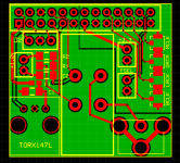
Attached is the really "first draft" of the layout (37 X 35 mm) where are still missing the pot connector, the led and some pins that I still need to clarify:
- In the I2S side I see the pins ISO RXD IN and ISO TXD OUT. Which is the purpose of those pins? Which kind of connectors are required?
- The power led output need a resistor for the led?
- Are requested the U.FL for the pins FPGA SLV and FPGA MCLK OUT?
- About the SPDIF transformer, I see that has been mentioned as a good candidate the AudioNote (Audio Note) and I am using the relevant dimension. Any other "bigger" transformer are foreseen?
Thanks and Regards,
Enrico
Attachments
Hi Ray,
The GB will be a good idea but I would like to complete the design first and share here the layout for any suggestion, mistakes, etc...
Actually my first idea was to have an easy way to connect the I2S through the U.FL but having all the inputs options in the same pcb can be a nice to have for others.
I just complete the Toslink part and I just receive a post from Paul where he strongly recommend to do not use the 3,3V from the DAC but provide an external supply. Something to revise...
Attached is the really "first draft" of the layout (37 X 35 mm) where are still missing the pot connector, the led and some pins that I still need to clarify:
- In the I2S side I see the pins ISO RXD IN and ISO TXD OUT. Which is the purpose of those pins? Which kind of connectors are required?
- The power led output need a resistor for the led?
- Are requested the U.FL for the pins FPGA SLV and FPGA MCLK OUT?
- About the SPDIF transformer, I see that has been mentioned as a good candidate the AudioNote (Audio Note) and I am using the relevant dimension. Any other "bigger" transformer are foreseen?
Thanks and Regards,
Enrico
Nice design!
Probably can add a 3.3V LDO for Toslink and draw 5V from the DAC?
Together with u-fl, you might also consider adding solder pads for the more durable SMA connectors, I heard Ian is heading that way in his new board.
Some people might need AES/EBU input, too.
Last edited:
Hi enrico
Lovely design and super fast .
For group buy
myint67 2 pcb
Hi Myint,
Thanks for your super fast and enthusiastic reply
")
The board is not yet finalized, the one that I post is just the first layout and I need some information before to complete and test it. I am sure some body will reply to my questions and it will not take long time to be ready
I will let you know when I will be ready and if there is some interest for a GB I will open a dedicate thread avoiding confusion here
Regards,
Enrico
You can download while playing, but need to trigger a filter reload by changing sample rate....
Great! Makes A/B testing much easier.
The ES9018 based new version?
My current dac is the first version of the ES9018 dacend, I was in the first group buy. They made some tweaks for the 2nd version. The main change was to add isolation to the Amanero interface.
At some point, when I get this working, and I'll compare the two.
Randy
The newest version exactly. Fellow diy'er caad presented his slightly modded v1 to me. Very nice indeed. Still I hope the dam1021 will beat it in the end with all the bells and whistles.
Comparison files
Hi
Just to have an idea how this DAC sounds I recorded a few files in a DA AD Looprecording.
I used a RME UFX as the Computerinterface, the input AD is a PCM 4222 Evaluationboard with a transformer frontend, bypassing the input electronics, one Loop is with the RME DA the other one the Dam1021, with 7v AC powering and RCA Spdif input, as a reference I submit the original file, too. Volume is adjusted as good as possible. File format is Wave 44.1 Khz 24 Bit.
It is just a short snippet of a track (Copyright, you know), but I think you can get a pretty good idea how that thing sounds.
https://dl.dropboxusercontent.com/u/45336197/comparison files DAM1021.zip
Thanks for listening.
Tobias
Hi Ray,
I just complete the Toslink part and I just receive a post from Paul where he strongly recommend to do not use the 3,3V from the DAC but provide an external supply. Something to revise...
Attached is the really "first draft" of the layout (37 X 35 mm) where are still missing the pot connector, the led and some pins that I still need to clarify:
Thanks and Regards,
Enrico
Looks good! I don't know if it's necessary, but you may want to include an inductor at the toslink receiver. Also, I know when I've worked with i2s I needed to keep my lines as short as possible, so it might be better if the uFL pads could be even closer to the connector pin outs--but I'd totally defer to people with more experience in this. I'd want one of these boards too!
An advice: If you have a DC-cuppeled chain, power up the DAM as first and power it down as last.
I had the DAM directely at my main amps and turned it off, wich resulted in a very nasty noise and the DC protection circuit (of the amp) turned the amp off.
AC/DC coupled- no matter what this always should be standard procedure. Always has been always will be.
Looks good! I don't know if it's necessary, but you may want to include an inductor at the toslink receiver. Also, I know when I've worked with i2s I needed to keep my lines as short as possible, so it might be better if the uFL pads could be even closer to the connector pin outs--but I'd totally defer to people with more experience in this. I'd want one of these boards too!
Agree regarding the u.fl pads. Make the board longer on the other side of the inputs, and put the u.fl pads as close to the pins as possible. Otherwise it looks really great.
Talking about filters....
HQPlayer seems to be the reference and their best filters is what they calls "Poly-Sinc" filters, but I don't seems to be able to find any info what they are exactly.... Anybody know something ?
There is something called "Windowed Sinc" filters, have found some references and t.ex. the ScopeFIR package can generate them.
Anybody knows of other tools that can generate them, preferable no or low cost ?
Any other ideas to what the best filters actually are ?
I'm sure you have seen this already, but just in case....
Sinc function - Wikipedia, the free encyclopedia
The sinc function looks like an excellent approach to reducing ringing. I'm sorry, but I'm no help in implementing it into a filter.
Also see Wikipedia "Reconstruction Filter" and the Common Filters section which talks about windowed sinc filters and higher order versions without ringing. Please note that this is typical Wikipedia and suited to someone like me that is new to the topic.
Last edited:
- Home
- Vendor's Bazaar
- Reference DAC Module - Discrete R-2R Sign Magnitude 24 bit 384 KHz