Hi Søren
Any news or predictions about launch date of dam1121?
Regards, L.C.
Anyone?
Thanks.

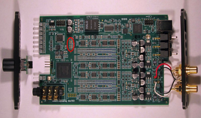
For people who want to use two boards from different production lots in balanced mode here is how each of the four vref buffers look like from the factory:
Original rev1: 10R series resistors, 22 uF output capacitor, 330 pF feedback capacitor and 499R feedback resistor
Factory upd rev1 and prod rev2: 0.1R series resistor, 47 uF output capacitor, 499R resistors mounted in both capacitor and feedback resistor position, creating an effective 0.050R vref buffer output impedance.
Prod rev3: 0.1R series resistor, 47 uF + 3x 100 uF output capacitors, 1K00 resistor mounted in feedback capacitor position (orange), 301R resistor mounted in feedback resistor position (yellow), creating an effective 0.025R vref buffer output impedance.
Colors on attached drawing:
Red: Output capacitor.
Blue: Series Resistor.
Orange: Feedback capacitor (now used for resistors).
Yellow: Feedback resistor.
Thank you Soren,
that is exactly the answer I wanted.
Do I need to have a look at something else, maybe the power supply caps (cause they are bigger in Rev3)? Or doesn't that make any difference and the only thing that needs to be done is the new arrangement of the Vref-buffer?
The muting will be done with the muting board from Normundss.
Johannes
They've changed info after I posted, thanks.Hello LazyCat,
have a look at soekris.dk
They say it will be available March 2016

Danes are famous for their design but Sören, the silkscreen on the front needs som work. Must be some retired B&O folks that would like som therapy activity?
//
//
Danes are famous for their design but Sören, the silkscreen on the front needs som work. Must be some retired B&O folks that would like som therapy activity?
//
What's wrong with that, I like to keep things clean and simple ? Anyway, I consider what's inside more important....
What's wrong with that, I like to keep things clean and simple ? Anyway, I consider what's inside more important....
+1 Couldn't agree more, I like the simple silkscreen and absolutely hate it when designers feel the need to put logos, text and all sorts of other nonsense on a PCB.
+1 Couldn't agree more, I like the simple silkscreen and absolutely hate it when designers feel the need to put logos, text and all sorts of other nonsense on a PCB.
I believe TNT was talking about the dac1101 alu front....
Danes are famous for their design but Sören, the silkscreen on the front needs som work. Must be some retired B&O folks that would like som therapy activity?
//
B&O folks have always had a great design sense so i fon't know what you mean.
I agree the front looks too "DIY" in the bad sense for a finished product. Beauty might only be skin deep but this looks like good old time Letraset transfers... and too fat/big for a start.
B&O folks have always had a great design sense so i fon't know what you mean.
I agree the front looks too "DIY" in the bad sense for a finished product. Beauty might only be skin deep but this looks like good old time Letraset transfers... and too fat/big for a start.
My idee was to take in som B&O resources to help with the design... 😉
//
I believe TNT was talking about the dac1101 alu front....
My bad, I read 'silkscreen' and figured he meant the PCB, but I see the USB DAC has silkscreen printing as well.
B&O folks have always had a great design sense so i fon't know what you mean.
I agree the front looks too "DIY" in the bad sense for a finished product. Beauty might only be skin deep but this looks like good old time Letraset transfers... and too fat/big for a start.
Notice the size of the dac1101, the front plate is only 20mm x 108mm so the text is actually not that big, I prioritized readability over beauty....
Notice the size of the dac1101, the front plate is only 20mm x 108mm so the text is actually not that big, I prioritized readability over beauty....
I wouldn't worry about it, your DAC needs to be evaluated by merit of its performance, not how lush the packaging, or how fancy the printing on the case is.
The holes are nom 26 mil - 0.66 mm diameter, most smaller caps up to Ø10 are spec'ed at 0.5-0.6 mm and should fit....
Btw, I forgot to mark + and - on the PCB, will mark a picture at some point, until then:
C166-C168, C172-C174: Plus is towards the XLR plugs.
C169-C171, C175-C177: Plus is away from the XLR plugs.
I'll recommend to verify with a multimeter....
The lead spacing is 2.54mm?
i see you've eventually switched to fixed frequency clocks
are they 22/24 or 44/48
is the firmware different or applicable to the diy boards
it is something that might be worth trying
And then the short jitter buffer strategy from the original boards can't be applied anymore... how is it solved and how does it impact performance?
//
//
i see you've eventually switched to fixed frequency clocks
are they 22/24 or 44/48
is the firmware different or applicable to the diy boards
it is something that might be worth trying
The dac1101 is USB only input, with asynchronous clocking, so there is no need for a programmable clock, that why two cheaper oscillators are used, still low jitter ones.
The dac1101 is a little different than the dam1021, so off course it have it's own (derived) firmware.
The dac1101 is USB only input, with asynchronous clocking, so there is no need for a programmable clock, that why two cheaper oscillators are used, still low jitter ones.
The dac1101 is a little different than the dam1021, so off course it have it's own (derived) firmware.
Would an XMOS chip even work with a programmable clock on its own? Every reference USB to I2S converter always calls for its own pair. Understandable you would just use those clocks for everything else too.
- Home
- Vendor's Bazaar
- Reference DAC Module - Discrete R-2R Sign Magnitude 24 bit 384 KHz