Hi Sonnya,
this morning I've bought some modules via your website.
I think to use a pair with my HP Hifiman he-6, that is very power hungry, and the others with my Audio Physic speakers.
Have you ever considered to use your V1.7 as planar magnetic hp amp?
Frank
Hi Frank.
First: Thanks for the order.
Secondly: I have thought about it, but not in this scale. 5W into 50Ohm is 16Vrms. . To run it in full class A for the headphones i would bias it at 0.3A (15mV on the sense resistors).
You will not be able to hear a hiss in the headphones with this drive requirement.
For supply voltage i would run it at approx. +/-25VDC . That is an toroid with 18VAC secondary.
For this configuration the power consumption per channel is 15W.
So to get rid of the heat i would advice a 1K/W heatsink per channel.. Could be a SK100 150mm or a SK466 in 50 - 75mm length.
http://www.fischerelektronik.de/web_fischer/en_GB/heatsinks/A01/Standard%20extruded%20heatsinks/PR/SK100_/$productCard/dimensionParameters/index.xhtml
SK 466, Standard extruded heatsinks, Heatsinks f.cool, Fischer Elektronik
I hope it is usefull.
Best regards
Sonny
BL drive connection diagram
For those of you who have purchased the BL drive module or intend to do so, i have attached a connection diagram for the BL drive module.
It describes how to connect using the TSSA V1.7 but the wiring is essentially the same when using with other amps.
When used with First One by Lazycat, one should observe that the mosfets used (Lateral) has a maximum current of 16Apeak. So the peak voltage generated into 4R is 64Vpeak. => 500Watt into 4R with appropriate cooling.
Who those who want to run into 2R with Balanced drive 3 - 4 pairs of mosfet per amplifier (6 - 8 pairs in total per channel) module is necessary. But then again 16A x 3 would produce 2KW into 2R... he he he.....
So that would be something like the 2 x TSSA V8 + BL drive module.
Attachments
Thanks a lot for the hints.
For this project I'd like to use an old case and transformer from a Musical Fidelity A1 amp (20W into 8 Ohms).
Do you think that 100va is enough? And what about his heatsink roof?
I'll put inside a Calvin buffer (whose sound is "wonderful") with a dual Salas shunt supply.
Frank
For this project I'd like to use an old case and transformer from a Musical Fidelity A1 amp (20W into 8 Ohms).
Do you think that 100va is enough? And what about his heatsink roof?
I'll put inside a Calvin buffer (whose sound is "wonderful") with a dual Salas shunt supply.
Frank
Sonya, I am toying with the idea of trying a RIAA stage based on phonocobe and phonoclone v3, from RJM on the forum. How do you think your discrete Osama would perform against spec'd opa627. It will compete with the wonderful Salas FSP. Here is the link to the thread on the basic concept of the RIAA.
http://www.diyaudio.com/forums/audio-sector/151938-phono-stage.html
RJM Audio - Printed Circuit Boards
http://www.diyaudio.com/forums/audio-sector/151938-phono-stage.html
RJM Audio - Printed Circuit Boards
I think this is plane wrong build. Sorry RJM.
But i have worked with microphones and have worked on getting noise level down in a system where we needed high gain. I would do the first stage and second stage completely different.
Of course the network setting the RIAA curve is ok. No doubt about that.
But i would reverse first stage. Voltage in, current out. - discrete of course.
secondly remove R3 as we already have an current source.
Third: Leave U2 and R6 as it is, but C1,R5+C2 to GND instead of output of U2.
This leaves U2 with constant gain and impedances. negative input of U2 will be at virtual gnd.
If more gain is need it can be done in the first stage (V to I) or add a second opamp after U2.
I would also rescale R5, R6, C1 and C2 by a factor 100. R5 = 1.1K, R6 = 7.5K, C1 = 100nF and C2 = 290nF. This will bring the noise down a lot.
My CFB opamp can be used but i would suggest the JFET VFB i am working on. The reason is the size of the feedback resistor r6. R6 should be even lower for the CFB opamp, but not for the JFET VFB opamp.
The JFET VFB opamp is an folded cascode design, to be able to get single stage gain stage like CFB.
I am bit tired now. But it is something i will follow up on.
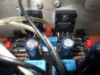
Time was high I assembled mine too. A better behaving amp version than the 1.6 for sure. Biases fast and stable -much easier than the previous- with miniscule offset. Some say use 240mA which is about 0Tc for double die parts (is it?), some say use as much as you can with MOSFETS to aid gm sag and extend the A part of A/AB class. I just went by comfortable heat criteria for my sinks so I let 450mA Ib circulate. PSU is the same, a second order Darlington Cmult with big Toshiba BJT on a chunky sink, F&T caps.
Listened only for a little, but it takes just a minute to know its a better amp than 1.6. Control, 3D, distinction, expression, are next level. Not sure if I could feel some subtly hyped mid overtone color, maybe the RIFA shunting the feedback lytics showing off a little but I should give it a week of play to say.
All in all a success. Sonny, congrats.")
Listened only for a little, but it takes just a minute to know its a better amp than 1.6. Control, 3D, distinction, expression, are next level. Not sure if I could feel some subtly hyped mid overtone color, maybe the RIFA shunting the feedback lytics showing off a little but I should give it a week of play to say.
All in all a success. Sonny, congrats.
Attachments
No, I use 95dB_SPL/W direct radiator 4 Ohm DIY speakers based on a couple of Taiwanese car audio ovals per side, a pro audio 6 inch French mid and a modified 1 inch Ti dome. Medium to small room still does not dictate that much of a controlled throw need. Noise level is church mouse quiet.And you use horns? Right !?
How is the noise level.
And thanks. Good you like it.
In my experience the AMP is especially good with speaker which is above 85db spl level. I like Raidho a lot but they are hungry after power. But salas you gave me appetite for building something with raal and maybe phl.
Thanks salas and buzzforb
Sent from my iPhone using Tapatalk
Thanks salas and buzzforb
Sent from my iPhone using Tapatalk
- Status
- This old topic is closed. If you want to reopen this topic, contact a moderator using the "Report Post" button.
- Home
- Vendor's Bazaar
- TSSA V1.7 mosfet Current feedback amp module