Sonny hi,
Got around to check mine too and when the output passed 38V P-P there it burst out. Could listen to the MOSFETS buzzing along too.
The 470pF U2 D to S cap cured it. Thanks.
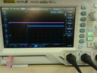
BTW I still get a bit peaky corners square wave like this one. Its there if lower frequency test signal also. What best compromise method do you possibly recommend to iron it out?

I do not see it as a problem, but C12 and C13 can be changed to an higher Value.
150 or 220pF.
I will see to find some silvered mica ones in those values to test at a point. As I am suspicious of small peaks on the square's corners could be hardening transient tonality a bit in any amp. Maybe there is more musicality to squeeze out of the 1.7. BTW the bandwidth is 750KHZ now (anti oscillation capacitor mod included).
Hello Sonnya, any update on the progress of the TSSA headphone amp?
I ahve the circuit on my table, but i am curious about the optimal gain for headphone amps... Any suggestions????
I ahve the circuit on my table, but i am curious about the optimal gain for headphone amps... Any suggestions????
gain of 4 (6db) would be ideal enough to cater 16-300 ohm phones. Some phones could go as 600, but quite rare. High impedance phones (300/600) usually don't need a lot of current but voltage only.
Planar phones such from hifiman, audeze, etc. usually stay in 32ohms, but they need a lot if currents to sing. Though not always, these phones usually benefited from pushpull or bridged type of last stage.
The drive current is set to 2A peak so there should be plenty of power.
Sorry that I just jumped in. I did follow only a bit on VSSA and then TSSA, with my limited knowlede on electronics. What is the gain of this TSSA 1.7?
No problem. The standard gain is 21x or 26.4dB
Hello Sonny,
That gain will be too high for headphones. Hopefully you could come up with lower gain for haedphone use, once your health and time allow you to work in the design.
Thanks, David.
Yes i have an progress on the V4. I have first seen it now as i have been sick all last week and had a lot to catch up on.
The V4 board has got a thinner layout so that is could fit on a 75mm heatsink.
The new boards are ordered and they will be here on the 16. march.
Hi Sonny
When will the new boards be available?
Cheers
Yeah, let us know your mod
Thanks
Do
Salas,
Please post what you come up with. I am a sucker for soft corners. I like the idea that this amp can sound even better than it already does.
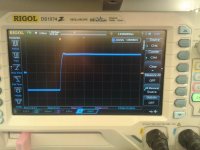
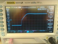
Before I had any proper values SM caps for that (could not find any locally), Vgeorge came up to test since he has some SM values in his stash. He sent me screenshots and we discussed. Conclusion is that compensating there is not productive. The square becomes slower for slew rate and eventually distorted in shape, before the little pointy corner fully goes. Demonstrably, Sonny already had brought the amp to equilibrium regarding the overall design including tradeoff between non linear Ciss of the output MOSFETs (Drain out amp shows Miller), damping, and speed. So no VAS comp tweak helps further. Its down to the design concept. Maybe it would take a CFP OPS to buffer and/or some comp in the bias CCS speed, don't know. Those would bring in another set of worries nonetheless. Lets wait for Sonny to possibly evolve future versions with time to also examine such details. He is well aware of the fine traits in this line of amps obviously.
Below shots from left to right order are with 100pF (standard), 150pF, 300pF VAS comp capacitors.
Attachments
Meantime where you all are waiting on me...
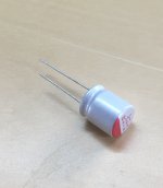
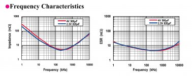
I have found an electrolytic cap that makes is possible to remove bypass caps for C2 and C3 (C4 and C5 is the bypass caps)
I can get this one in 1000uF which means that instead of 1.5Hz cutoff it is now 3Hz.
As seen in the curves attached the ESL and ESR values are that low that up to 5MHz it outperforms the Panasonic FC types.
I have them in stock for around 0.67€/capacitor.
Attachments
I have found an electrolytic cap that makes is possible to remove bypass caps for C2 and C3 (C4 and C5 is the bypass caps)
I had some difficulties following the cap-discussion. I they are expected to better or solve something I am interested in 8 to. Will you make a post about the mods/tweaks?
- Status
- This old topic is closed. If you want to reopen this topic, contact a moderator using the "Report Post" button.
- Home
- Vendor's Bazaar
- TSSA V1.7 mosfet Current feedback amp module