ADM 7151 regulator
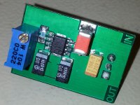
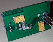
ADM 7151 regulator module
A quite new chip which do a very good job.
First of all I have to thanks here to glt who bring it up the information about this new chip (at least for me). After reading his article and the datasheet of the chip, I thought at once that this is the thing we should use it for audio purposes. So here it is... in case other peoples will be interested to use it.
The details are to be found in its data sheet. There are some results of my tests, which are to be seen here by too.
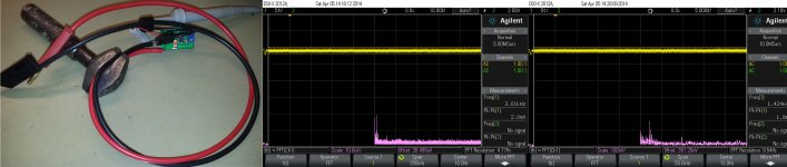
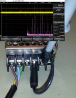
This test illustrated here it were done with the regulator loaded for 280mA. The chip as is mounted on this PCB it were working well for this load at no more than 38 dg. C.
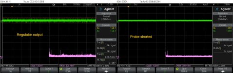
It was difficult for me to see something on the scope, because the exceptional performances of this device. That because I put it beside the snapshot of the scope with its probe shorted. The spikes to be seen on FFT are coming from the scope itself (not so happy to discover that... but it may be also some parasitic levels/frequencies induced from my environment).
In may tests I could see a very slow variation of the regulated tension (output) of no more than 4mV at a 4V output level (with load).
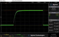
Because of the high capacities involved, the start up time is quite slow, but who cares about, when the performances are so high? After 3 sec. it is switched ON, become just stone stabilized.
The chip is specified with a input voltage up to 16v. As the datasheet state, the best PSRR (94db) is around 1v headroom. So this regulator it should be used after a 5v more or less another standard regulator, or after a PSU adjusted accordingly to the table in the data sheet. I will recommend using this module presented here as a final/second regulator in a power system, or as local regulator for noise sensitive devices, as ADC/DAC chips, clock oscillators.
After adjustment to the desired output level, it is recommended to be used a fixed resistor value, for even better stability.
As it is designed, the regulator it fits perfect for use with Buffalo DAC, or in what so ever audio application (standard 3 pins interface).
There are two version of the chip: one is suitable for 3,3v range use, another one it may be used for up to 5v domain. Actually the best performer is the version which it can regulate into 4v. It looks to me that the designers were initially focused on powering 3,3v devices. Then they developed the chip to meet the needs for 5v standard power. These regulators, developed specially for RF domain use, are also excellent to power clock oscillators.
ADM 7151 regulator module
A quite new chip which do a very good job.
First of all I have to thanks here to glt who bring it up the information about this new chip (at least for me). After reading his article and the datasheet of the chip, I thought at once that this is the thing we should use it for audio purposes. So here it is... in case other peoples will be interested to use it.
The details are to be found in its data sheet. There are some results of my tests, which are to be seen here by too.
This test illustrated here it were done with the regulator loaded for 280mA. The chip as is mounted on this PCB it were working well for this load at no more than 38 dg. C.
It was difficult for me to see something on the scope, because the exceptional performances of this device. That because I put it beside the snapshot of the scope with its probe shorted. The spikes to be seen on FFT are coming from the scope itself (not so happy to discover that... but it may be also some parasitic levels/frequencies induced from my environment).
In may tests I could see a very slow variation of the regulated tension (output) of no more than 4mV at a 4V output level (with load).
Because of the high capacities involved, the start up time is quite slow, but who cares about, when the performances are so high? After 3 sec. it is switched ON, become just stone stabilized.
The chip is specified with a input voltage up to 16v. As the datasheet state, the best PSRR (94db) is around 1v headroom. So this regulator it should be used after a 5v more or less another standard regulator, or after a PSU adjusted accordingly to the table in the data sheet. I will recommend using this module presented here as a final/second regulator in a power system, or as local regulator for noise sensitive devices, as ADC/DAC chips, clock oscillators.
After adjustment to the desired output level, it is recommended to be used a fixed resistor value, for even better stability.
As it is designed, the regulator it fits perfect for use with Buffalo DAC, or in what so ever audio application (standard 3 pins interface).
There are two version of the chip: one is suitable for 3,3v range use, another one it may be used for up to 5v domain. Actually the best performer is the version which it can regulate into 4v. It looks to me that the designers were initially focused on powering 3,3v devices. Then they developed the chip to meet the needs for 5v standard power. These regulators, developed specially for RF domain use, are also excellent to power clock oscillators.
Attachments
Last edited:
I know, the measurement it were not taken in a very accurate mode. The noise one can see in the pictured regulator output is not the noise coming from that regulator, but the HF noises (many Mhz) induced into the connections wires, between the PSU and the regulator itself. The scope is quite good, but the measurement set up was not very professional...
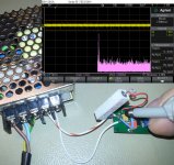
If one take a look at the FFT calculations, then can one understand that is about a extreme low noise generated by the regulator for a enough large bandwidth. The FFT is centred on 10Hz, and the span is 100Khz... And the vertical scale is 100nV/div.... As you can see, there is nothing above 100nV on FFT, for the whole 100Khz spectre.
Anyway, this chip have quite exceptional performances. I have used in my design bigger capacities than specified in datasheet. This it slow a little bit more the start up, but it bring a little bit more out of the chip, special in the very low frequency spectre.
I think you may find a better answer to your question, if you will take a look over the data sheet of this chip.
Last edited:
Some more measurements...
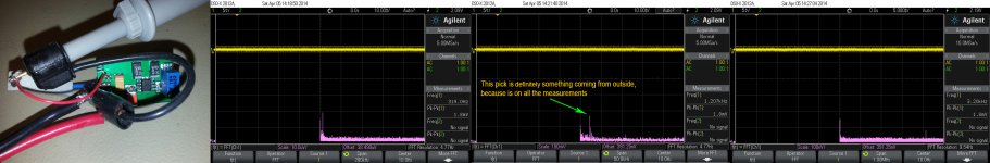
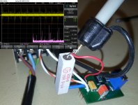
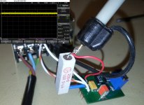
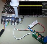
I`ve chosen first a worst case scenario: my regulator powered from a bad/noisy SMPS. You can see the snap shots of the SMPS output with two FFT scales. Then the regulator`s output when powered from SMPS.
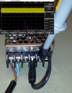
Second test is to measure the regulator output feed it with the same 5,5v from a serial laboratory PSU. Regulator out: 4v on 280mA load.
Third test is to show how it looks on scope when the probe are connected only to the wires (no power involved).
Some preliminary conclusions:
There is a FFT pick which is always present. This it came for sure from somewhere in the environment, or from the scope itself. It is not in connection with the noise floor of the regulator.
This regulator is definitely NOT to be used after a SMPS, even though it reduce quite much the input noises. It is a nonsense of using a such low noise device.
The rest of conclusions is on your own...
I`ve chosen first a worst case scenario: my regulator powered from a bad/noisy SMPS. You can see the snap shots of the SMPS output with two FFT scales. Then the regulator`s output when powered from SMPS.
Second test is to measure the regulator output feed it with the same 5,5v from a serial laboratory PSU. Regulator out: 4v on 280mA load.
Third test is to show how it looks on scope when the probe are connected only to the wires (no power involved).
Some preliminary conclusions:
There is a FFT pick which is always present. This it came for sure from somewhere in the environment, or from the scope itself. It is not in connection with the noise floor of the regulator.
This regulator is definitely NOT to be used after a SMPS, even though it reduce quite much the input noises. It is a nonsense of using a such low noise device.
The rest of conclusions is on your own...
Attachments
-
 OnlyWires - diffrentFFTscales.jpg554.3 KB · Views: 229
 -
 REG powered by LabSerialPSU - FFT diffrent scales.jpg692.1 KB · Views: 256
 -
 REG powered by SMPS-zoom 10µv-div.jpg625.1 KB · Views: 279
 -
 REG powered by SMPS.jpg597.6 KB · Views: 289
 -
 SMPSout - zoomFFT 10µv-div NOISE.jpg571.4 KB · Views: 297
 -
 SMPSoutput 5,5vDC.jpg577.5 KB · Views: 887
Last edited:
It's quite hard to find this voltage regulator in shops. I found the 4V version in UK. It's pricey o.o
$10 CAD here (Digi-key prices)
 Since you're offering the PCB for sale, and not open-source, I've moved this thread to Vendors. Confine any sales and promotional efforts to this thread.
Will you consider adding the circuit for additional emitter follower? This regulator is capable of 800ma, but the heat dissipation will be a problem.
I think it is not a big deal to use it for a powerful power supply. Following components after it (emitter follower) it may induce more noise in the system, and negate the reason to use a component with such performances.
More reasonable is to power this regulator from a conventional serial PSU which may include a 317, 78xxx, etc. This regulator is meant to be used for quite low power/currents for local regulation of the noise sensitive devices, as clocks, ADC/DAC chips, and so on. Actually the chip is designed for RF domain.
Using this chip to drive high current it may degrade its performances. Best specifications are into 400mA. Quite plenty...
But the module as it is it can be used to further developing of a powerful PSU, or instead of a standard regulator chip. One is free to experiment with it. I did not insisted in this direction...
- Status
- This old topic is closed. If you want to reopen this topic, contact a moderator using the "Report Post" button.
- Home
- Vendor's Bazaar
- The King of the regulators - ADM 7151