Eagle 25W PSU beta testing
We have been beta testing the new high power (25W) Eagle PSU for some time now and the results have been outstanding.
The testers have been using the high power Eagle on Lencos, Garrards and Empire tables with motors as high as 22W. The heatsink temp of the Eagle stays very cool, the highest reported temp of ~90°F after extended playing times.


Walker Precision Motor Controller
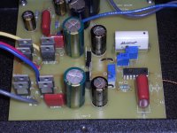
I had a chance to thoroughly go through and test a Walker Precision Motor Controller (PMC) this weekend. At $1650 retail, I was expecting to find some rather sophisticated electronics, given all the hype on their website and from the audio press. Instead I found a very simple design utilizing an XR2206 function generator connected to a single chip LM1875 20W amp to drive a step up transformer. There are several DIY kits available on the audio blogs that provide this same level of design, but those kits are an order of magnitude better in quality. I actually thought the person who sent it to me was playing some sort of practical joke and had to confirm via e-mail that this was indeed a production unit.
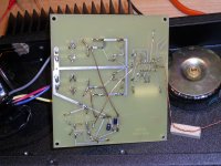
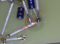
Even more shocking than the circuit design was the poor build quality. All of the circuitry was located on a single sided PCB that looked like it was laid out with tape and mylar and etched by hand in a tray (see photos). No solder mask, hand soldered and interconnect wires all scattered about. One of the solder joints appeared to be shorted (B+ to Ground!), but it must have had the smallest of gaps as it still functioned. It's incomprehensible that ANY commercial mfr (let alone Walker who has a very good reputation) would release a product this simple and built this shabbily at ANY price point, but especially at $1650.
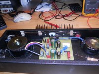
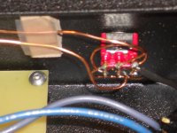
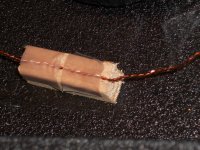
The rest of the circuit including the front panel mounted 33/45 switch and trimmer pots was connected to the main PCB via point to point wiring and instead of tied downs, was taped to small wooden blocks that were glued to the case bottom.
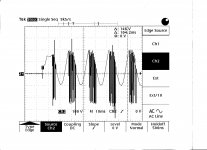
The output of the LM1875 is directly connected to the step up xfmr (no coupling cap) so any offset voltage will severely load the amplifier. This was apparent at start up as the unit always broke into oscillations for the first 2-3 seconds when plugged in (the unit does not have an on-off switch; as soon as it is plugged in, it's on and stays running, consuming power until unplugged). There are also no protection diodes on the output of the chip amp; as this is driving a highly inductive load, it's remarkable that it doesn't self destruct when switching the motor on/off.
As for measurements, the frequency is under analog control and continuously adjustable, so frequency accuracy is a non-spec at this point. However, as I received the unit, 33 RPM was set at 58.5Hz and 45 RPM was set to 79.0 Hz. The party I received the unit from stated that they could not start their table in 45 RPM mode, but had to start in 33 then switch to 45 RPM each time.
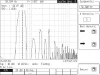
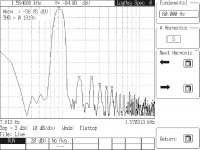
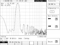
Output voltage is internally adjustable and was set to 114VAC with no load. The output sagged to 110.8VAC at 4W, 107.9VAC at 8W, 105.1VAC at 12W, 102.5VAC at 16W and 99.8VAC at 20W. There is no facility to lower the voltage once the platter is up to speed. Distortion was just over 1% at both 33 and 45 RPM. This is not surprising as the XR2206 is not known for low distortion sine waves as it is really a triangle wave generator with internal compensation to round the waveform top peaks. There was no additional circuitry such as a low pass filter or buffer to reduce distortion, despite their claim that the signal is super clean and low distortion.
About the only good thing I can say about the Walker PMC is the case is very solid and well made (although a bit on the large side). As for the rest of it, buy a cheap XR2206 osc PCB and LM1875 amp PCB (about $5.95 and $6.50 respectively on e-Bay) instead and put them in a Hammond case. The quality will be much better and you'll save $1500 in the process.
I had a chance to thoroughly go through and test a Walker Precision Motor Controller (PMC) this weekend. At $1650 retail, I was expecting to find some rather sophisticated electronics, given all the hype on their website and from the audio press. Instead I found a very simple design utilizing an XR2206 function generator connected to a single chip LM1875 20W amp to drive a step up transformer. There are several DIY kits available on the audio blogs that provide this same level of design, but those kits are an order of magnitude better in quality. I actually thought the person who sent it to me was playing some sort of practical joke and had to confirm via e-mail that this was indeed a production unit.
Even more shocking than the circuit design was the poor build quality. All of the circuitry was located on a single sided PCB that looked like it was laid out with tape and mylar and etched by hand in a tray (see photos). No solder mask, hand soldered and interconnect wires all scattered about. One of the solder joints appeared to be shorted (B+ to Ground!), but it must have had the smallest of gaps as it still functioned. It's incomprehensible that ANY commercial mfr (let alone Walker who has a very good reputation) would release a product this simple and built this shabbily at ANY price point, but especially at $1650.
The rest of the circuit including the front panel mounted 33/45 switch and trimmer pots was connected to the main PCB via point to point wiring and instead of tied downs, was taped to small wooden blocks that were glued to the case bottom.
The output of the LM1875 is directly connected to the step up xfmr (no coupling cap) so any offset voltage will severely load the amplifier. This was apparent at start up as the unit always broke into oscillations for the first 2-3 seconds when plugged in (the unit does not have an on-off switch; as soon as it is plugged in, it's on and stays running, consuming power until unplugged). There are also no protection diodes on the output of the chip amp; as this is driving a highly inductive load, it's remarkable that it doesn't self destruct when switching the motor on/off.
As for measurements, the frequency is under analog control and continuously adjustable, so frequency accuracy is a non-spec at this point. However, as I received the unit, 33 RPM was set at 58.5Hz and 45 RPM was set to 79.0 Hz. The party I received the unit from stated that they could not start their table in 45 RPM mode, but had to start in 33 then switch to 45 RPM each time.
Output voltage is internally adjustable and was set to 114VAC with no load. The output sagged to 110.8VAC at 4W, 107.9VAC at 8W, 105.1VAC at 12W, 102.5VAC at 16W and 99.8VAC at 20W. There is no facility to lower the voltage once the platter is up to speed. Distortion was just over 1% at both 33 and 45 RPM. This is not surprising as the XR2206 is not known for low distortion sine waves as it is really a triangle wave generator with internal compensation to round the waveform top peaks. There was no additional circuitry such as a low pass filter or buffer to reduce distortion, despite their claim that the signal is super clean and low distortion.
About the only good thing I can say about the Walker PMC is the case is very solid and well made (although a bit on the large side). As for the rest of it, buy a cheap XR2206 osc PCB and LM1875 amp PCB (about $5.95 and $6.50 respectively on e-Bay) instead and put them in a Hammond case. The quality will be much better and you'll save $1500 in the process.
Attachments
Last edited:
Walker Precision Motor Controller
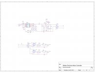
Just finished the schematic of the Walker controller. They did something rather unusual on the output: The step up xfmr is a 30W dual secondary (low voltage side) design but the controller only drives one of the secondary windings, so it is essentially a 15W output max. I guess this makes sense as the LM1875 is only rated at 20W.
Just finished the schematic of the Walker controller. They did something rather unusual on the output: The step up xfmr is a 30W dual secondary (low voltage side) design but the controller only drives one of the secondary windings, so it is essentially a 15W output max. I guess this makes sense as the LM1875 is only rated at 20W.
Attachments
Improved distortion for Falcon output
We just completed a change to the Falcon PSU to reduce the distortion of the output waveform. Previously, it was ~0.7% at full voltage (115VAC) and ~0.4% at 85VAC.
The latest version will allow adjustment down to 75VAC and the distortion is reduced to 0.13% at full voltage (14dB improvement) and 0.1% at 75VAC.
Compare that with 0.4%/0.2% for the VPI SDS and 1.2% for the Walker PMC, we are 9dB better than the SDS and 19dB better than the Walker.
Attachments

We have been beta testing a 25W version of the Eagle PSU for months now and it works just fine on the older Garrards, Lencos, Empires, etc. Crystal controlled, direct digital synthesis, reduced voltage output and tachometer feedback holds the platter speed within ±0.005 RPM. Why reinvent the wheel (and why tubes)?
http://www.diyaudio.com/forums/vendors-bazaar/252742-digital-turntable-tachometer-dds-based-psu-19.html
http://www.diyaudio.com/forums/vendors-bazaar/252742-digital-turntable-tachometer-dds-based-psu-19.html
Eagle PSU for Lenco L75
I am a Lenco L75 user from Dubai, U.A.E. and I have recently purchased the Eagle PSU & RoadRunner Speed Control System directly from Phoenix Engineering and after 3 weeks of running it, everything is working perfectly in my setup and am very pleased with how it is ensuring the correct speed of my turntable, and more importantly now I am always listening at the correct "pitch" as was recorded by the artists / musicians. Not everyone can appreciate what that means. But a slight deviation in speed affects proportionately the musical pitch, that can turn a note to a Sharp or a Flat accordingly.
Aside from my Lenco I also have a Technics SL-1200Mk2. It is considered a DJ Turntable with a variable speed controller called "Pitch Control". I learned from this that a fractional change in platter speed meant an audible change in the intonation of a track / song. And with this knowledge lodged somewhere in my brain, it started a search for a reliable way to maintain the correct speed for my Lenco. That search led me to the RoadRunner & Eagle PSU combination, and what a wonderful solution it is.
Let me share with you my setup:
> Lenco L75 rebuilt, on a hard wood plinth
> Double / Stacked Original Lenco Platters, using sorbothane ring as decoupler
> Jelco SA-750D 9" Tonearm
> MC Cartridge Denon 103R & Benz Micro Gold
> Step-Up Transformer using Hashimoto HM-7s
> Musical Surroundings Nova II Phono Preamp
> Line Magnetic LM-518ia 845 SET Tube Amplifier / Sansui Au607NRA2 SS Amplifier
> Sonus Faber Signum Speakers
I would like to mention how pleasant it has been to deal and communicate with Bill Carlin at Phoenix Engineering, who provided me with all the answers to my questions prior to purchasing this system, and guided me throughout my installation and was always an email away whenever I needed some assistance.
I have encountered very few suppliers / manufacturers in the audio world who has the same level of commitment to their customers, and goes the extra mile to ensure that their product performs as promised at the hands of their customers. For that alone I recommend him as a trusted source / supplier.
Aside from the obvious improvement in pitch, I also hear an enriched attack of the music. The Eagle PSU provides excellent torque, whose power can even be adjusted at the Eagle Controller to suit our preference.
Since I am also a DIYer who built my own Lenco from scratch, picking up tips & advice from different forums such as here at diyaudio and lencoheaven, I decided to make an installation video for this speed control system, so that others may see how this system is installed and how it operates and works for a Lenco Turntable. And I hope other fellow Lenco / Idler Wheel Turntable users can benefit from this system as I have.
https://www.youtube.com/watch?v=4IGzgvRSNXk
- Robert
Attachments
Can I ask an ignorant question about ac motors?
Do ac motors have a linear relationship between input frequency and output rpm?
In other words if
60hz -> x spindle rpm -> 33 1/3 platter rpm
If the 60 hz increases by 10%, does it follow
66hz -> 1.1x spindle rpm -> 1.1 times 33 1/3 platter rpm?
I'm trying to wrap my head around how the falcon knows the rpm without a feedback tach.
AC synchronous motor speed
AC synchronous motors are locked to the driving frequency so the speed is controlled by changing frequency not voltage. The speed (RPM) is Freq x 60/#pole pairs. So for a 12 pole motor at 60 Hz, the speed is 3600/6 or 600 RPM. A 300 RPM motor (designed for 60 Hz) has 24 poles. We can change the frequency of the output signal in 35µHz steps so the speed control is very precise. The factory default frequency for 33.333 RPM is 60Hz, but in calibration mode, you can adjust this in 0.01 RPM steps. Once the base frequency is set, changing the "tempo" setting in 0.1 RPM steps using the +/- buttons is easy and the speed stays synchronized and accurate.
AC synch motors also exhibit no loss in speed due to torque loads. They hold 100% of their speed until the cogging torque is exceeded at which point the speed drops to zero. This is not true with DC motors or AC induction motors. DC motor speed is controlled by voltage, therefore our controllers do not work with them; AC induction motor speed is a function of frequency and voltage, although the speed is not locked to the driving frequency as in AC synch motors, but is related so speed control is a little more difficult.
You have to remember also, even if the motor is spinning at a constant speed, the platter may not be. The primary culprit is belt creep and is dependent on a lot of variables that can be difficult to control. Using just the PSU, it is possible to dial in the speed of the platter initially but it is better to let the table warm up before doing this. With the RoadRunner feedback, the speed is set automatically and eliminates long term drift, compensates for varying needle drag (from beginning to end of an LP side), and warming of the bearing oil and belt.
Last edited:
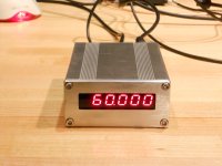
High Resolution Frequency Counter
I was doing some testing over the weekend and needed a high resolution frequency counter, something that would give me Hertz to 2 or 3 decimal places. Normally, freq counters count the number of cycles received in 1 second and display the frequency in Hz. If you want 0.1 Hz resolution, you have to count the number of cycles for 10 Sec and display it with the decimal point adjusted to 1 place. Three decimal places of resolution would need 1000 second gate time or 16 minutes 40 seconds between updates using this method.
To count extremely slow speeds, a different approach is used: Use the event width as the gate, count how many high frequency clock pulses accumulate during that time and take the reciprocal to give you the frequency. This is basically what we do with the RoadRunner tachometer where the gate time is 1.8 Seconds at 33 RPM. But as you go up in frequency (shorter gate time), the resolution suffers unless you have an extremely high clock rate accumulating.
Using the RoadRunner tach as a platform, I did a hybrid version of the 2: Accumulate high frequency clock pulses for 100 cycles of the input waveform. This gave me 3 decimal digits of resolution with a variable gate time equal to: Gt=100/Freq Hz. For 60 Hz, this works out to 1.6667 Sec update rate. At 10 Hz, it is 10 Sec. I limited the range from 1Hz to 100Hz. Using the serial data output (normally connected to the PSU), I can log the results of the display on a computer using HyperTerminal.
One of the first things I tested was the frequency of the wall power to see how accurate and stable it was (see 60Hz Wall Power.TXT attached). As expected, it was fairly accurate, but it varied constantly (at least every 1.67 Sec). The largest deviation in my measurement was from 59.981 Hz on the low side to 60.029 Hz on the high side. This translates to 33.322 RPM - 33.335 RPM worst case. The sample to sample variation was almost always 0.003-0.006 Hz. Not a big swing , but as it is changing constantly, it is much more audibly noticeable and may account for the time smear (loss of sound stage focus) that many report when listening to a turntable connected to the wall power.
I also did a readout on the Falcon PSU frequency stability and you can see from the attached file, it is much better, staying within the margin of trigger ambiguity (±1 count).
I wonder if there would be any market for this as a frequency counter?
Attachments
Rega RP6 cable for Falcon PSU
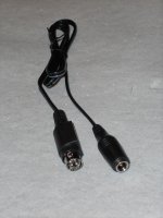
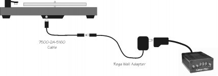
We've had some requests to use the Falcon PSU with a Rega RP6. The RP6 comes with the TT-PSU and a different interface board on the table than the other RP series tables (4 pin DIN plug only). We've developed a cable that will allow you to use the Falcon PSU with the Rega RP6.
The Rega wall adapter plugs into the output of the Falcon and the new cable goes between the output of the Rega wall adapter and the table.
The RoadRunner can also be used with the RP6.
Attachments
Should have said something a few weeks ago.
My ROAD RUNNER/EAGLE combo has brought me nothing but pleasure.
This thing is so perfectly realized that every time I see it and use it I am grateful I have one in my possession.
It is compact unlike the PS300 I was using to control speed on my Lenco. This makes me smile when I see floor instead of that giant rectangle on my floor.
Seeing ROAD RUNNER say your table is spinning at 33.33_ brings great satisfaction but the sound this allows out of my turntable makes this one of those things you can not live without once you have grown accustomed to its abilities.
These are about as close to perfect as any audio component I have ever possessed. What would be required for a product to approach perfection? I can think of nothing that would make it better, not that I would complain if an improvement is made.
I can think of one thing to complain about - I did notice the MEANWELL switcher did make my table radio make some strange noises. I do not hear any strange affects while the system is playing LPs.
My understanding was the RP6 was the only Rega variant that had only the 4 pin DIN connector; Does the RP7 have both the 4 pin DIN and the 2.5mm socket at the table input?
If the RP7 has the 2.5mm socket, you do not need the new cable, just plug the table's wall adapter into the Falcon output.
If the RP7 only has the 4 pin DIN socket, you would need the new cable and the connection is as shown in the diagram above.
The tach will work with any table as long as there is clearance for the magnet/sensor assembly (~0.25"). On the P3 & P6 there was more than adequate spacing at the edge of the platter (in fact the sensor had to be elevated from the plinth to get the Hall Effect sensor close enough to the magnet). The magnet/sensor can also be placed on the subplatter, but the trigger will be more consistent on the outside edge of the platter.
The P7 does use a 4-pin DIN connector-in fact the P7, like the newer RP6 does not have an on-board power supply. The difference is that the P7 cannot use the standard Rega TT PSU-it must use the PSU specifically designed for it.
What is the optimal distance to have between the magnet and the sensor?
What is the optimal distance to have between the magnet and the sensor?
- Status
- This old topic is closed. If you want to reopen this topic, contact a moderator using the "Report Post" button.
- Home
- Vendor's Bazaar
- Digital Turntable Tachometer and DDS based PSU