Buffer preamplifier can be ladder attenuator or shunt attenuator type PCB.
Are those opamps (on pot pcb)?? What are they for?
I have high quality potmeters with similar shaft. Have any idea how to attach those to regular knob?
let's see if Google has an answer on how to successfully robbing a bank..")
It's very easy (to successfully robbing a bank)! It is harder to get away
If opamps are used in the signal path, and the performance is still stellar, the next step will be buying 3 amplifiers for an active analog crossover system
LC, what about motorized potentiometer ?
Hi Theo
TKD doesn't have them and I don't find it very important at the moment, the quality is all that matters at volume control hehe

First One Black&White exhibiton chassis
Hi all
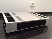
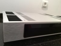
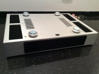
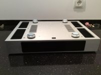
First One exhibiton-show chassis in B&W design just came into assembly line.
Me happy
Hi all
First One exhibiton-show chassis in B&W design just came into assembly line.
Me happy
Attachments
Me happy
Me want! That's a really nice looking case. How many of the amplifier modules will fit in it comfortably?
Hi Dyna
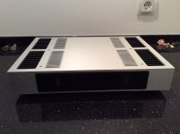
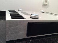
C1 chassis is thermally optimized to accept two First One modules, two SMPS1200A400, two DC sense protection modules and in this last B&W iteration stereo VU rms-peak meter with three indication selections: VU off, -10 dB power level, 0 dB power level, also comes behind the front plate. See the post #1416 for detailed installation layout inside C1 chassis.
You could actually mecahnically fit in four First one modules and two SMPS1200A400 but in this case output bias current would have to be reduced to half.
First One battery powered preamp will also be installed in the same B&W C1 chassis, pictures follows in a day or two.
L.C.
Hi Theo
DC sense PCB-s are here, 96 pcs. available at the moment, will be produced more if any interest.
They'll be sold as a small PCB kit, including:
- DC sense PCB, 1 pcs.
- optocoupler, 1 pcs.
The rest of the passive materials should be provided by the user, nothing special few resistors, diodes, capacitors.
DC sense PCB triggers the optocoupler at more than +/-1 V DC on the speaker output, which closes its output darlington to very low Uce_sat, thus close the circuit from shutdown pin to GND of any SMPS. Switch Imax=100 mA.
Price 8,00 EUR for one DC sense PCB kit.
GB starts bellow.
Regards, L.C.
Hi LC,
1 - What is the binding post spacing in mm (standard 19, 32)? I want to make sure it fits in my chassis already made holes.
2 - Does it work with DPS-500 and DPS-400 series SMPS from AudioPower?
3 - Do you still have some in stock?
Thanks
Do
Hi Do
1 - 25 mm spacing, 9 mm holes diameter
2 - no clue, DC sense output is Emitter-Collector pins in isolation (optocoupler output) with 100 mA current capability. Normally acting like a switch should be compatible with variety of SMPS
3 - yes, a lot
L.C.
Bad luck for me... My hole pattern is ~30mm, oh well...
Maybe I can use one of the holes on a binding post and solder the second one with a cable? Would that work ok?
If yes, please send me an invoice for a stereo kit
Thanks
Do
How much for the black/white chassis.
It's a little too early to tell, however it will be calculated, all chassis prices revealed soon.

Just take off 1 mm from side flank of each of the four holes (two on chassis two on DC sense PCB) and you could align them both. Direct fixation with nuts then possible just like intended to.
Would it also work the way I was thinking of doing it? Positive side on binding post and gnd with 12 gauge wire soldered from binding post to module?
Thanks
Do
- Home
- Vendor's Bazaar
- First One - mosFET amplifier module