danny_66 4x DC sense kit
Theodosis O. 2x kit
Brianco x2 kit
quan+ 4 kits.
danny_66 4x DC sense kit
Theodosis O. 2x kit
Brianco x2 kit
quan+ 4 kits.
flyboi 4 kits
ZZoran 4kits
Theodosis O. 2x kit
Brianco x2 kit
quan+ 4 kits.
flyboi 4 kits
ZZoran 4kits
danny_66 4x DC sense kit
Theodosis O. 2x kit
Brianco x2 kit
quan+ 4 kits.
flyboi 4 kits
ZZoran 4kits
giannettino x2 DC Sense kit
Theodosis O. 2x kit
Brianco x2 kit
quan+ 4 kits.
flyboi 4 kits
ZZoran 4kits
giannettino x2 DC Sense kit
danny_66 4x DC sense kit
Theodosis O. 2x kit
Brianco x2 kit
quan+ 4 kits.
flyboi 4 kits
ZZoran 4kits
giannettino x2 DC Sense kit
Pinnocchio 2 kits
Theodosis O. 2x kit
Brianco x2 kit
quan+ 4 kits.
flyboi 4 kits
ZZoran 4kits
giannettino x2 DC Sense kit
Pinnocchio 2 kits
danny_66 4x DC sense kit
Theodosis O. 2x kit
Brianco x2 kit
quan+ 4 kits.
flyboi 4 kits
ZZoran 4kits
giannettino x2 DC Sense kit
Pinnocchio 2 kits
Catal 6 kits
Theodosis O. 2x kit
Brianco x2 kit
quan+ 4 kits.
flyboi 4 kits
ZZoran 4kits
giannettino x2 DC Sense kit
Pinnocchio 2 kits
Catal 6 kits
danny_66 4x DC sense kit
Theodosis O. 2x kit
Brianco x2 kit
quan+ 4 kits.
flyboi 4 kits
ZZoran 4kits
giannettino x2 DC Sense kit
Pinnocchio 2 kits
Catal 6 kits
Rick G. 2 kits
Theodosis O. 2x kit
Brianco x2 kit
quan+ 4 kits.
flyboi 4 kits
ZZoran 4kits
giannettino x2 DC Sense kit
Pinnocchio 2 kits
Catal 6 kits
Rick G. 2 kits
Last edited:
Great idea... let's do it right
With great respect, LC . . .
I'm a bit of a safety nut and would argue that nothing is 'fool proof', but we can require a bigger fool to prove us wrong 😀
Your earth-isolation networks back in #838 (?) are very similar to what I've adopted for years now - can really work magic at keeping ground-loop currents at bay. However, I would like to point out a couple of changes for your consideration:
1st - the diodes, these should be rated for a PIV well above the peak mains voltage with a current rating that at least betters the primary mains fuse (at the inlet) - and some might argue for better than the mains breaker rating. WHY? Simple, should there be some catastrophic failure in the PS and either mains or some other HV rail were to short to the PS-gnd with impunity, I for one would want to know there's a sturdy and capable path to the Earth line (okay, so maybe at 0.7V up) which would [functionally] guarantee a proper fail-safe shutdown scenario. In the grand scheme of things, chump change to implement and does not degrade the network's intended function.
2nd - in parallel with or in lieu of the 1k resistor, add a 1-22nF, 600v film cap to give stray RF currents in the PS-gnd conductors a low[er] impedance path to the Earth line.
3rd - I'd love to hear the debate as to why the 1k resistor is included, seems useless to me - assuming one isn't bothered by the potential for the PS-gnd to float 0.7V above the Earth line - hardly a danger or threat.
Cheers!
No need to, chassis is still 100% earthed, fool proof. 😀
With great respect, LC . . .
I'm a bit of a safety nut and would argue that nothing is 'fool proof', but we can require a bigger fool to prove us wrong 😀
Your earth-isolation networks back in #838 (?) are very similar to what I've adopted for years now - can really work magic at keeping ground-loop currents at bay. However, I would like to point out a couple of changes for your consideration:
1st - the diodes, these should be rated for a PIV well above the peak mains voltage with a current rating that at least betters the primary mains fuse (at the inlet) - and some might argue for better than the mains breaker rating. WHY? Simple, should there be some catastrophic failure in the PS and either mains or some other HV rail were to short to the PS-gnd with impunity, I for one would want to know there's a sturdy and capable path to the Earth line (okay, so maybe at 0.7V up) which would [functionally] guarantee a proper fail-safe shutdown scenario. In the grand scheme of things, chump change to implement and does not degrade the network's intended function.
2nd - in parallel with or in lieu of the 1k resistor, add a 1-22nF, 600v film cap to give stray RF currents in the PS-gnd conductors a low[er] impedance path to the Earth line.
3rd - I'd love to hear the debate as to why the 1k resistor is included, seems useless to me - assuming one isn't bothered by the potential for the PS-gnd to float 0.7V above the Earth line - hardly a danger or threat.
Cheers!
1st - the diodes, these should be rated for a PIV well above the peak mains voltage with a current rating that at least betters the primary mains fuse (at the inlet) - and some might argue for better than the mains breaker rating. WHY? Simple, should there be some catastrophic failure in the PS and either mains or some other HV rail were to short to the PS-gnd with impunity, I for one would want to know there's a sturdy and capable path to the Earth line (okay, so maybe at 0.7V up) which would [functionally] guarantee a proper fail-safe shutdown scenario. In the grand scheme of things, chump change to implement and does not degrade the network's intended function.
So something like MUR1560G?
Do
Save the MURs
Sure, but why not like this:
Digi-Key Part Number GBU8M-BPMS-ND
1 0.98000 0.98
Micro Commercial Co
GBU8M-BP
Description RECT BRIDGE GPP 8A 1000V GBU
...cross-strap and you have a double back-to-back pair!
Cheers!
So something like MUR1560G?Do
Sure, but why not like this:
Digi-Key Part Number GBU8M-BPMS-ND
1 0.98000 0.98
Micro Commercial Co
GBU8M-BP
Description RECT BRIDGE GPP 8A 1000V GBU
...cross-strap and you have a double back-to-back pair!
Cheers!
Would you provide the optimal modules/wiring layout for full balanced connection, including ground lifting ? (pair of FO with one smps1200a180 per channel)... should the modules be adjacent mounted on heatsink to minimize distance between input terminals? or minimize distance between speaker output terminals?Full balanced and bridge versions need good ballanced source, correct grounding and good interconnect cables. If any of these fails, sound's gone. One simple unbalanced interconnect cable makes a great difference, imagine all the rest.
The dc sense is only for first one?
No, it's universal DC sense circuit with low pass filter -46 dB/10 Hz actuating opto darlington. The normally opened output serves to shutdown any power supply having input for this function. 😎
For example SMPS1200A400 connector J4 pin 9, pin 10 are the ones to be connected to DC sense. 😉
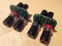
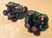
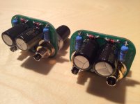
Below is how finished DC sense PCB looks like. 🙂
Attachments

Would you provide the optimal modules/wiring layout for full balanced connection, including ground lifting ? (pair of FO with one smps1200a180 per channel)... should the modules be adjacent mounted on heatsink to minimize distance between input terminals? or minimize distance between speaker output terminals?
Full balanced block sch is included in user's manual delivered by the modules.
GND lift is easy, the same DRD circuit used as with stereo block sch.
Modules are always mounted in a way that the power transistors are at the bottom edge of the heatsink, so the heat is coming from below to the top. In this way heatsink is maximally efficiently used for best thermal dissipation. Always use heatsink having 0,5°/K/W or better.
Recommendation for Bridged mode PS ?
Hi LC,
Okay, so I get the impedance limitations in bridged mode (effective 2 ohm avg. per module, 250W, ~31.6Vpk ==> 15.8Apk)... great! What I don't know is what the sag is for either the SMPS1200A400 or the __A180 PS modules when delivering that sort of current. Reason is simple, I'd like to use the most appropriate PS module; and from the copious posts here I gather there's yet no contender to the SMPS1200's throne position. Thoughts?
Cheers!
Hi Dominic
Now to the questions:
- in bridge mode min 4 Ohm impedance is recommended, meaning 4 Ohm in average if looking impedance curve, so it can also be less than 3 Ohm somewhere in the bass region, but that's OK if the average is still around 4 Ohm. The limit here is the output current which is 16 Amax and if looking to SOAR chart of the outputs, you can see these are very robust semis, at 100 Vdc they still easily sink/source 2,5 A 😱
- since the modules are calibrated at +/- 63 V, at +/-42 V idle current would be a little bit lower, but still recalibration back to 280 mA (complete module's idle current) can easily be readjusted by trimmer TR3
- definitely LL1540 Lundahl line input transformer
In bridge mode at +/- 42 V PSU voltage you would easily get 500 W/4 Ohm and still be well in a SOAR. 😎
Hi LC,
Okay, so I get the impedance limitations in bridged mode (effective 2 ohm avg. per module, 250W, ~31.6Vpk ==> 15.8Apk)... great! What I don't know is what the sag is for either the SMPS1200A400 or the __A180 PS modules when delivering that sort of current. Reason is simple, I'd like to use the most appropriate PS module; and from the copious posts here I gather there's yet no contender to the SMPS1200's throne position. Thoughts?
Cheers!
as well as I asked for the physical layout of two modules on the shared heatsink... should they be mounted as close as possible to each other, and which edges/sides? if +/- of balanced input terminals are too distant, the inducted parasitic errors may differ and will not cancel no more ... I always thought that optimal position for power transistors is at center of heatsink, not on edge, as heat transfers more even to all metal bladesFull balanced block sch is included in user's manual delivered by the modules.
GND lift is easy, the same DRD circuit used as with stereo block sch.
Modules are always mounted in a way that the power transistors are at the bottom edge of the heatsink, so the heat is coming from below to the top. In this way heatsink is maximally efficiently used for best thermal dissipation. Always use heatsink having 0,5°/K/W or better.
Hi LC,
Okay, so I get the impedance limitations in bridged mode (effective 2 ohm avg. per module, 250W, ~31.6Vpk ==> 15.8Apk)... great! What I don't know is what the sag is for either the SMPS1200A400 or the __A180 PS modules when delivering that sort of current. Reason is simple, I'd like to use the most appropriate PS module; and from the copious posts here I gather there's yet no contender to the SMPS1200's throne position. Thoughts?
Cheers!
1200A180 is the one to go with balanced version of the First One, since it can deliver 13 Arms (18,45 Ap) at 46 V. In reality it would drop for a few volts but that's still aceptable. Two First One modules per channel in balanced version with 1200A180 would easily give 500 Wrms/4 Ohm load.

as well as I asked for the physical layout of two modules on the shared heatsink... should they be mounted as close as possible to each other, and which edges/sides? if +/- of balanced input terminals are too distant, the inducted parasitic errors may differ and will not cancel no more ... I always thought that optimal position for power transistors is at center of heatsink, not on edge, as heat transfers more even to all metal blades
First One modules have to be mounted as I already explained, power transistors side at the lower edge of the heatsink, laterally each one at third from the heatsink's lateral edges. And this is of utmost priority, cabling is in a second plan.
Input cabling for each module should be of the same lenght, routed at the upper side of the modules, where the input is located on PCB, to the input XLR connector.
It occurs to me that for products such as this, it might be preferred to have two threads. One for build details/advice only. The other for listening impressions and comparisons to other components serving same purpose.
It gets very old sifting through posts for comparisons to similar type products.
It gets very old sifting through posts for comparisons to similar type products.
- Home
- Vendor's Bazaar
- First One - mosFET amplifier module