Just reread your post Eldam and I really can not make much of it. Too much info and questions mixed up. Please make a "mod-BOM" list so others can use your info in a structured way.
Just see it this way. With our BOM you could order your parts faultlessly (proven as you made a working V3), with your pdf no one can order at all unless he/she plows through large chunks of text with quite some noise and intermediate changes in between.
BTW I discovered these words "two caps discontinued" in your post. Which caps ? Which number in the schematic/BOM and which brand + type ? I now see you think different, I can not think /compute of telling one wheel of my car has a leaking tyre to the garage without mentioning it being the front left wheel....
Last edited:
More faster than a computer...
If anybody want to make it, it could be much appreciated as I spend a lot of time already. Don't want to hijack the first page of Gary also... People are free to read here what he want, peak up all he want: this thread is less longer than the John's thread. Sorry for whom with no time... I spent more time to make experiments and try to write it and respect the sharing spirit... Already explain to you my "philosophy" is to let understand the change, not dictate a BOM I think better, even if I believe it is !
Don't want also than most of the owner risk their standalone pcb (already "quoted of the day" above). This is just an alternative I believe better, at least at home ! I'm against bandwagoning. DIYaudio is more about sharing and understanding.
If an alternative BOM, it should be blessed by you your knight majesty. You said you will try it on an umpopulated pcb but I can understand you have no time anymore for that, i ask nothing, just share.
I believe Gary maid also maybe deeper change (PS ?) and don't post it by respect and intteluctual honnesty as he would maybe think (as I) your BOM is good enough.... and neutral. Btw he is the OP; so....
Here I write just for maybe less 20 rabid people like you and me ! clap clap, clap clap !
PS : all the constructor ref (of the new caps I choosed) can be found in my pdf or already exist with the parts of your BOM.
Last edited:
Just reread your post Eldam and I really can not make much of it. Too much info and questions mixed up. Please make a "mod-BOM" list so others can use your info in a structured way.
......... with your pdf no one can order at all unless he/she plows through large chunks of text with quite some noise and intermediate changes in between.l....
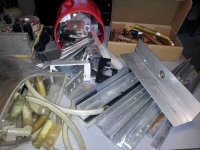
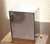
Eldam, let me try to support JP's request with a different example. In my quest for a usable liquid cooled amp chassis I went (and am presently) through many iterations, combinations and configurations. Your PDF and general information shows your dedication and effort to produce a "workable" set of mods to achive high, though subjective, performance. Unfortunately, we are getting something similar to me trying to include all this stuff and descriptions of the complete project process. If someone desired to duplicate the end result as shown in the second photo, I could give them a list of materials, set of cut and bend guides and a construction outline. Nobody cares, needs or wants to have an excessive dialogue on the pile or descriptions of things that didn't contribute to the final unit.
We all appreciate your effort and understand that you are hesitant to claim perfection, but those efforts and time spent are of no use unless distilled down to a usable format - read list. We all enjoy inserting a bit of our personalities and some color into our posts, but at some point that only confuses and frustrates forum members.
Let me respectfully suggest you disengage from the dialogue for a period of time - cause there really is no urgency evolved here. Some of us might enjoy trying your favored configuration - but just can't see what that is. There is too much information on the "pile"
") . We have all the time we need to wait for you to clarify and simplify what you have discovered and put it into a usable form.
. We have all the time we need to wait for you to clarify and simplify what you have discovered and put it into a usable form.Attachments
Last edited:
You said you will try it on an unpopulated pcb but I can understand you have no time anymore for that, I ask nothing, just share.
It is right I will build such a new V3. I just won't be trying out all caps on this world not will I spent days debating about them. This DAC is good and it is with good standard parts like in the BOM. I am not in the flavor, seasoning, tastes camp. It simply needs to be good and adapting the sound character to other stuff in the chain is not my cup of tea. If the chain has weak points one should not compensate for that by changing the other innocent devices IMO. A weak chain will never be stronger than its weakest link. Better do something about that weakest link.
All this is not in the way of improving the V3, I will be the last to object to improvements as you know. It surprises me no one has changed the coils and beads till now....
Let me respectfully suggest you disengage from the dialogue for a period of time - cause there really is no urgency evolved here. Some of us might enjoy trying your favored configuration - but just can't see what that is. There is too much information on the "pile"
Well put Bob ! Your written english is very good for a frenchman
Last edited:
Hope it's clearer but have to say, Gary understood perfectly all my mods before !
Changes on Dacboard (MNF PART NUMBER or common desciption) in relation to the genuine BOM (parts GB not involved as different from the BOM):
C4: 0.1 uf COG ( SMD 605 case size)
C7-C20-C19-C5: FCA1210C105M-G2
C17: 1 Uf X7R + 0.1 uF COG (both SMD 605 case size)
C29-C30: FKP2C014701D00HSSD (on genuine BOM) : (2.5%)
C21-C13-C8: Panasonic 25SEP10M
C22: first choice discontinued Sanyo OSCON SP >= 330 uF ; second choice : Nichicon PLEOJ471MDO1 (6.3v) (read the pdf page36 for understanding)
C32: standard Black Gate 1 uf ; (BG-N(X) said to be better- not tested myself : I haven't it !)
C36: unpopulated
X6: silvered copper wires soldered on RCA X6 output with silvered RCAs plugs (no phoenix connector or other,the less the better: look for direct soldered Rcas; no find yet)
X2 : no wires ; pcb BNC jack : Amphenol 112419 (to be soldered under the pcb to match the polarity)
Changes on PS board :
C2-C4: FCA1210C105M-G2 (choice on the genuine BOM)
C5-C8 : 0.1 Wima MKS2 (choice on the genuine BOM) (try with and without C5)
C9 : 47 uf standard Black-Gate
Tamura transformer beams a lot : 10 cm wire between the two boards - transformer position the farer on the active chips the better !
Not tested but advised :
a second common chocke but before the PS board (compatible with your wall voltage 110 or 230 V)
a ultra fast recovry diodes bridges
But don't ask me why anymore those choices... read the thread and the pdf even if hard !
I hope that helps.
Last edited:

Thanks !
1. Don't do this: C17: 1 Uf X7R + 0.1 uF COG (both SMD 605 case size) Oscillation of the MIC may happen. BTW I think you mean 0805 size ?
2. C22: the PLEOJ471MDO1 is not found at Farnell and Mouser .... Google also does not know it so it might be a typo ?
3. The Tamura does not radiate more than any other EI core transformer, in fact it is even less. Still the farther away from the circuits the better.
Last edited:
Thanks !
1. Don't do this: C17: 1 Uf X7R + 0.1 uF COG (both SMD 605 case size) Oscillation of the MIC may happen. BTW I think you mean 0805 size ?
2. C22: the PLEOJ471MDO1 is not found at Farnell and Mouser .... Google also does not know it so it might be a typo ?
3. The Tamura does not radiate more than any other EI core transformer, in fact it is even less. Still the farther away from the circuits the better.
1 : no : 604 (the size below 805). You would advise to go with 1 uf tantalum + 10 nF COG (official datasheet) or 100 nf COG? don't hear anything harsch, maybe the 10 uf x7r before the MICREL ? I followed Marce fellow advices : the lower size for the case, the better the inductance. He advised also several values (but for very high Fhz): 10 nf+100nf+1 Uf e.g. But in theory, he didn't measure on this particular board.
2 : PLE0J471MDO1 Nichicon | Mouser
3 : I didn't tried other transformer.
Last edited:
Eldam it seems you missed the test of Androa76 that had severe oscillation with paralleling certain ceramic caps for C17. Again I see our choice for 4.7 µF tantalum was not a bad one. The MIC regs don't like ultra low ESR caps despite the ESR of the used beads. Low ESR is no problem but ultra low ESR can be a problem.
Marce has a lot of knowledge but he has no V3 PCB AFAIK. Don't take and spread advices from paper that are not tested. If you want to try then use equipment to check if no side effects happen instead of talking in colors and tastes. It might very well be that the reg is oscillating which explains a perceived difference. Parallelling with small ceramic caps does not work out OK on C17.
http://www.diyaudio.com/forums/digital-line-level/246003-modifying-subbu-v3-dac-44.html#post3970672
You probably mean 0603 size SMD ? You have given twice the wrong case type now. There also should be an "0" before the case type so 0603 or 0805.
Slowly just slowly my advice very probably will be to just use the original BOM we made to avoid all this hassle. The V3 performs without problems and it sounds very good with BOM parts.
Last edited:
And you asked me to write a BOM ... Just supress the C17 line but do'nt kill all the rest just for that, it will be intellectually not honest before try it; My conf must be very good to sound very fine even with the C17 problem (i will fix it, yes I saw the Andrea post but wanted to have your opinion : yourself you changed your BOM with thantalum 4.7 for a further COG 1 uf !!!! Look at what you writed yourself before critize me with rude maneers ! Pffff !).
Btw it's the Modyfing thread not the Assembly thread, eerybody is already ok to say the genuine BOM is good enough... and better inside it with the good choices (see above) !
I think you are flooding in a glass and are just focused on détails like the size case... I think everybody understood the size was just before the 805... which is a Peugeot car... bigger than my 501 which is a pants !
Thank you for "this hassle" ! You're strange sometimes...And don't say to me anymore this is because the life is short !
So I'm not the OP, Gary will copy or not my BOM on him first page if he agrees the changes...
I just shared, do what you want, it's not a problem... and yes fellows : don't break your pcb if you have just one (already said but once more is not too much !)
... Just supress the C17 line but do'nt kill all the rest just for that, it will be intellectually not honest before try it; My conf must be very good to sound very fine even with the C17 problem (i will fix it, yes I saw the Andrea post but wanted to have your opinion : yourself you changed your BOM with thantalum 4.7 for a further COG 1 uf !!!! Look at what you writed yourself before critize me with rude maneers ! Pffff !).Btw it's the Modyfing thread not the Assembly thread, eerybody is already ok to say the genuine BOM is good enough... and better inside it with the good choices (see above) !
I think you are flooding in a glass and are just focused on détails like the size case... I think everybody understood the size was just before the 805... which is a Peugeot car... bigger than my 501 which is a pants !
Thank you for "this hassle" ! You're strange sometimes...And don't say to me anymore this is because the life is short !
So I'm not the OP, Gary will copy or not my BOM on him first page if he agrees the changes...
I just shared, do what you want, it's not a problem... and yes fellows : don't break your pcb if you have just one (already said but once more is not too much !)
Hi Gary,
Please change at least your first page about C17 and 1 uF X7R,I'm very worried about you and will be sad JP send Subbu to burn your house !  ... just for a hobby !
Or is it ok finaly with 1 uf COG ( of the size we want... but the lower the better inductance without forgett the zero before...pif paf boum and what your able to solder... something between the 80x and the 40x size I mean... with the zero before ...pif paf boum ) ... .
.
Please change at least your first page about C17 and 1 uF X7R,
I'm very worried about you and will be sad JP send Subbu to burn your house ! ... just for a hobby !Or is it ok finaly with 1 uf COG ( of the size we want... but the lower the better inductance without forgett the zero before...pif paf boum and what your able to solder... something between the 80x and the 40x size I mean... with the zero before ...pif paf boum ) ...
.
Last edited:
No, with C17 I went from 1 µF X7R to 4.7 µF tantalum, later I changed back because of builders experiences.
Many words don't make anything clearer. IMHO pushing people to read back through several pages and having to read chunks of text could be considered rude. We must think in detail as there are many builders and we want happy builders. Try to have 500+ happy builders using your methodology. If we had used another methodology everybody still would be busy fiddling with colors and tastes (and a heap of surplus parts). The results of our thinking is what everybody that built the V3 is listening to. Your method suits you, our method must suit many.
Any change of parts should be measured and checked with an oscilloscope, the days of throwing different parts on the V3 and judging by ear only are over. It would not surprise me the least that a V3 with BOM parts measures and sounds better than a 3 times resoldered V3 board with too large caps, ultra low ESR caps etc. "tuned" to a certain hifi chain. Solid engineering followed by testing is what makes a good device. A good DAC sounds good in any hifi chain.
BTW a BOM is a spread sheet which leaves no confusion. Part numbers, case sizes etc must be correct. Please no assumptions that all people will understand if there are mistakes in it. They likely won't as we also found out the hard way.
Last edited:
So what : what is the best choice finally with C17 ? You come back to the 4.7 ?
 Maybe my listening is better after because I just improved my soldering skill !
You are a little biased (get off the "little"). Many good measured DAC don't sound so good and I surmise you tested many conf also with the ears ! I'm not talking about your method btw?!
So try before my BOM (for the pleasure of your hobby if you always enjoy it ), talk after (before judging)! So many reproach without testing : you should test your dialectic with your scope sometimes. Did you see you just took the exemple of C17 (why me when so many people did the same with any reproach ?! Or the smt size case it was clear enough than 6 is lower than 8, why you stoped on the zero or the last number... I know the answer but let you find yourself why)
E.g. : C35, found myself the Wima is too tight with lake of notes end. I'm sure it measurs better than the Black Gate... at least at home (always said that !) found the BG better! Idem with C22 SEPC cap after tried 3 better choices (but also 4 or 5 worst !)... at least at home with no scopes... noise is flooded by the tablas of Zakir Hussain !
WHY C17 has oscillation with before a ferite bead and before a tantalum, I don't know, I'm a poor tweaker ! Btw I didn't hear no real différences with all the C17 conf, surmise sometimes someone can hear it because see it on the scope before... or have better ears than me. Not important, was already happy with the genuine BOM and more after my mods and just shared my listening impression for few rabed by caps rabbits (they have big ears) !
It could be interresting also for a better understanding to know the rest of your system : speakers, other speakers for verification, amp, headphones system. I think it could be explain also what you call flavors and why an AMR device could be more appreciate than an AYre device e.g. (it's picture...).
Finally I don't attack you or your BOM or the devices of the 500 happy owners. Be cool, it's just a shared hobby, no life is involved in this sort of engeneering ! If you try my few changes I hope you or anybody will appreciate and say what you think of it. Some don't care as they have a JG buffer also not on the BOM... that's life... T Ford is an old concept ! But true, the most important is to have a car if you want to drive... e.g. to take some holydays after a busy year !
Have a good soon week-end JP, I appreciate your work and your DAC a lot.
Maybe my listening is better after because I just improved my soldering skill !You are a little biased (get off the "little"). Many good measured DAC don't sound so good and I surmise you tested many conf also with the ears ! I'm not talking about your method btw?!
So try before my BOM (for the pleasure of your hobby if you always enjoy it ), talk after (before judging)! So many reproach without testing : you should test your dialectic with your scope sometimes. Did you see you just took the exemple of C17 (why me when so many people did the same with any reproach ?! Or the smt size case
it was clear enough than 6 is lower than 8, why you stoped on the zero or the last number... I know the answer but let you find yourself why)E.g. : C35, found myself the Wima is too tight with lake of notes end. I'm sure it measurs better than the Black Gate... at least at home (always said that !) found the BG better! Idem with C22 SEPC cap after tried 3 better choices (but also 4 or 5 worst !)... at least at home with no scopes... noise is flooded by the tablas of Zakir Hussain !
WHY C17 has oscillation with before a ferite bead and before a tantalum, I don't know, I'm a poor tweaker ! Btw I didn't hear no real différences with all the C17 conf, surmise sometimes someone can hear it because see it on the scope before... or have better ears than me. Not important, was already happy with the genuine BOM and more after my mods and just shared my listening impression for few rabed by caps rabbits (they have big ears) !
It could be interresting also for a better understanding to know the rest of your system : speakers, other speakers for verification, amp, headphones system. I think it could be explain also what you call flavors and why an AMR device could be more appreciate than an AYre device e.g. (it's picture...).
Finally I don't attack you or your BOM or the devices of the 500 happy owners. Be cool, it's just a shared hobby, no life is involved in this sort of engeneering ! If you try my few changes I hope you or anybody will appreciate and say what you think of it. Some don't care as they have a JG buffer also not on the BOM... that's life... T Ford is an old concept ! But true, the most important is to have a car if you want to drive...
e.g. to take some holydays after a busy year !Have a good soon week-end JP, I appreciate your work and your DAC a lot.
Last edited:
Please don't let me say what I didn't ! It's a lie !
I know already that, wrote it already and i'm thankfull. It's not the question you are doing a mistanderstanding.
I just give a good alternative, that's all. People are free to test it or no. And responsible about themselves. THIS IS A MODYFING THREAD !
This is not a calling into question, It's strange than an adult think it is !
I have two boards, spend time to adapt it for my own pleasure and think the alternative is very good maybe be better at least in my system. It will be stupid to have bandwagoning without testing it before throw it ! In any case I have to accept these constant reproach. That's all. It's not important, I take it with humour as it's ridiculous at the end and not inteluctually honnest !
Very simple ! You are an adult: try it talk after... And whateever the gift, maneers stay important. But never judge before testing.
regards
Last edited:
So in the spirit of the thread subject and for an easier reading and finally to come back to more pacificate reading I give again my BOM with J-P correction about C17 and first as the OP of this thread the BOM of Gary copied in the first page of this thread:
"Additional comments added March 10, 2014
After considerable discussion in this thread, there is a consensus developing on a good set of mods and parts that could be the basis for a new BOM. If you don't feel like reading the entire thread, here is a short summary.
C17 - 1uf X7R MLCC Ceramic capacitor (many possible vendors)
C22 - 470uf 6.3v Panasonic SEPC 6SEPC470
C32 - 1uf Wima MKS2 with 2.5mm lead spacing - MKS0B041000F00KSSD
C35 - you should use either C32 or C35, but not both. If you want to experiment with larger values of Wima MKS2 that only come with 5mm lead spacing then use the C35 location instead of C32. You should not use a value >4.7uf or the sound gets worse.
C4 - 1uf Wima MKS2 with 5mm lead spacing - MKS2-1/50/10 or MKS2-1/63/5T or MKS2C041001F00KSSD "
Mine : (in relation to the offical BOM for all the other parts)
C4: 0.1 uf COG ( SMD case size, the smaller the better)
C7-C20-C19-C5: FCA1210C105M-G2
C29-C30: FKP2C014701D00HSSD (on genuine BOM) : (2.5%)
C21-C13-C8: Panasonic 25SEP10M
C22: first choice discontinued Sanyo OSCON SP >= 330 uF ; second choice : Nichicon PLE0J471MDO1 (6.3v) (read the pdf page36 for understanding)
C32: standard Black Gate 1 uf ; (BG-N(X) said to be better- not tested myself : I haven't it !)
C36: unpopulated
X6: silvered copper wires soldered on RCA X6 output with silvered RCAs plugs (no phoenix connector or other,the less the better: look for direct soldered Rcas; no find yet)
X2 : no wires ; pcb BNC jack : Amphenol 112419 (to be soldered under the pcb to match the polarity)
Changes on PS board :
C2-C4: FCA1210C105M-G2 (choice on the genuine BOM)
C5-C8 : 0.1 Wima MKS2 (choice on the genuine BOM) (try with and without C5)
C9 : 47 uf standard Black-Gate.
It is seen like a whole, I don't guaranty a result if you just peak up into this BOM !
Input of ANdroa76 fellow about C17:
"10uf tantal + 100nF x7r ..line on scope is almost completely straight. second best 4,7uf tantal and third one 1uf x7r ...after aded 0,1uf start oscillating. after aded 4,7uf or 10uf x7r ... enormous big oscilation."
So first choice would be after scope measurement: 10 uf Tantal + 100 nF X7R/COG; second choice the BOM one : 4.7 uF tantalum; the third choice has be reported to sound better by some but just with "ears". Choose on your own (guilty "conscience"). Small cases are always better because the inductance particulary about clock decoupling
Many report better final result with the JG buffer (design gifted for the ommunauty also).
And in spite of it's a modyfication thread I glue the warning of one of the Subbu creator : Jean-Paul fellow : Slowly just slowly my advice very probably will be to just use the original BOM. The V3 performs without problems and it sounds very good with BOM parts.
I just remove a part of the citation for a nicer reading in a pacify spirit to avoid selfdefense humour.
Hope it's nicer to read like that.
regards
Last edited:
- Home
- Vendor's Bazaar
- Modifying the Subbu V3 DAC