Do you mean to short these 4 points --- R19, R20, D5 and D6 with a short wire at each component if using smps power supply?
kp93300
Each resistor-diode pair shorten with one wire. By listening tests was confirmed more grip and better bass and even more resolution in mid-high region.

The 100 Hz ripple noticable at the output was the same as before (barely noticable), since we use CCS for the input stage.

They look like a good fit to me.
The case diameter on the 2200uF/6.3V is 10 mm
which is even smaller than the recommended cap.
so even better fit.
The Lead Spacing and External Widths are the
important specs. All good.
Capacitor dimensions for VSSA PCB:
- 10 uF/63 V, MKT, Vishay-Roederstein, 2 pcs
Lead Spacing: 15 mm
External Depth: 8.5 mm
External Height: 17.5 mm
External Width: 18 mm
- 2200 uF/6,3 V, FG, Nichicon, 2 pcs
Mfr. #: UFG0J222MHM
Lead Spacing: 5 mm
External Diameter: 12,5 mm
External Height: 25 mm
- 1000 uF/50 V, FG, Nichicon, 4 pcs
Mfr. #: UFG1H102MHM
Lead Spacing: 7,5 mm
External Diameter: 16 mm
External Height: 31,5 mm
Thanks for the help ichiban.

I would certainly recommend Nichicon FG, since they were tested and compared with all Panasonics types, and Nichicons are always way better soundwise.
Hello,
I would like to get 6 PCB sets
Thank you.
Bertrand
Please send your info to esl@siol.net
Please be very specific with address, quantities and everything else. Do not forget to mention your forum name.
")
An effect of the added 1mF + 1µF to the power Rails rather than the filter's suppression ?Each resistor-diode pair shorten with one wire. By listening tests was confirmed more grip and better bass and even more resolution in mid-high region.
Last edited:
An effect of the added 2mF to the power Rails rather than the filter's suppression ?
Hi Esperado

Last mont I extensively tested First One amp in more than ten versions. It was very intense and hard working period I must tell.
In the way I found out the best result when all stages are in low Z connection in both ends or in full circle sort of speaking, meaning from GND to rails always low Z connection. The ripple reduction by R-D-C filter is of course working, it falls from 150 mVpp to 10 mVpp at each rail potential, but that is meaningless since we use CCS to supply current to the input stage. So ripple reduction means nothing and sadly contributes to lower SQ at the end.
My recommendation as always, on step of change and than listening evaluation, otherwise you get technically perfect amp with dull SQ.
You're right on this method, my words were not to express a doubt about your input. But, as always, to try to understand the real reasons of the differences you noticed.My recommendation as always, on step of change and than listening evaluation, otherwise you get technically perfect amp with dull SQ.
Did-you tried a cap multiplier, CSS or regulator for VAS with exactly the same caps, power rail side ? (Yes, i suppose CSS for input stage do the job enough for it).
I understand lowZ reference (ground) side. Not DC (CSS is not really what we call low Z ;-)
PSRR is the is the Achilles' heel of CFAs. So no shame to try to improve it and have an amp less sensible to PSU quality.
This said, if everything had been explored, and the conclusion is "Simple is beautiful", it will save time and components for future designs.
Last edited:
1- Let-me think and explore a little more about this...Interesting...triple and their evils...1-Low Z between VAS and OP.
2- I will not explain it
2- I can bet on something around your nice idea to add open loop gain via the input stage without the lytic's problems (smiley here)
One thing was interesting, in the CFA Bonsai's thread, despite the low theoretical distortions achieved, was the evils (near 10MHz) of any added stage in the signal path... (conclusion done by my nose, see what i mean ;-).
Last edited:
1- Let-me think and explore a little more about this...Interesting...
2- I can bet on something around your nice idea to add open loop gain via the input stage without the lytic's problems (smiley here)
One thing was interesting, in the CFA Bonsai's thread, despite the low theoretical distortions achieved, was the evils of any added stage in the signal path... (conclusion done by my nose, see what i mean ;-).
Should be compared by listening, but I don't like diamond input stage since it brings more problems than solutions in reality. Low THD itself means nothing otherwise tube amps would not exist on the market any more.
Should be compared by listening, but I don't like diamond input stage since it brings more problems than solutions in reality. Low THD itself means nothing otherwise tube amps would not exist on the market any more.
Maybe a little of topic.
But what problems does it bring?
We both know that the VSA frontend struggles with the negative delta vbe og ~2mV/celcius. Meaining from cold to warm state -> Huge change is bias current in the frontend.
The AC coupled VSSA reduces it, but does not solve it. (Due to Rf/Rg of 1K in the VSSA and ~100R in the VSA)
With the diamond buffer, and closely coupling between all 4 transistors this problem is solved.
Agree on all those points. More than this, diamond input stage sort of kill the CFA soul and character: feedback in the emitter of the first input device...expansive transients behavior... Diamond bring evils peaks and oscillations at high frequencies or during brutal edges in CFAs... Is-it your experience too ?but I don't like diamond input stage since it brings more problems than solutions in reality. Low THD itself means nothing otherwise tube amps would not exist on the market any more.
In itself, the common emitter/ common base combination in the single input stage, because the ultra low collector level of the signal/feedback difference don't produce disagreeable or even noticeable HD.
Cleverly solved by the use of CSS ? CFAs are very special animals Ask more feeling and experience for good designs. Humble attitude and a deep experience of their savage character.Huge change is bias current in the frontend.
In the CFA thread, i noticed the approach was very VFA kind of...looking for HD instead of square waves and slew rate behavior etc...
That's why i'm very interested to build the Dadod's schematic and compare with my poorer measuring own CFA, or VSSA, just to confirm what i presume...
Last edited:
Maybe a little of topic.
But what problems does it bring?
Sound reproduction is not so good as with one part modulation only, sorry, tested.
VSSA showed thermal drift +/-1 mV of the output DC from cold start to normal operation without any extra method or DC servo and that is extraordinary achievement.
VAS bias current drifts from 12-15 mA but that has no influence to the output stage bias current since we have shunt bias regulator, independent to VAS bias current fluctuations.
The ccs does not Solve it unless it is thermally coupled and constructed to compensate for the bias drift.Agree on all those points. More than this, diamond input stage sort of kill the CFA soul and character: feedback in the emitter of the first input device...expansive transients behavior... Diamond bring evils peaks and oscillations at high frequencies or during brutal edges in CFAs... Is-it your experience too ?
In itself, the common emitter/ common base combination in the single input stage, because the ultra low collector level of the signal/feedback difference don't produce disagreeable or even noticeable HD.
Cleverly solved by the use of CSS ? CFAs are very special animals Ask more feeling and experience for good designs. Humble attitude and a deep experience of their savage character.
In the CFA thread, i noticed the approach was very VFA kind of...looking for HD instead of square waves and slew rate behavior etc...
That's why i'm very interested to build the Dadod's schematic and compare with my poorer measuring own CFA, or VSSA, just to confirm what i presume...
Regarding peaks. If it done right you do not have a peaking.
Andrej, i am not talking dc offset. I know that it works beautifully In the vssa. I am talking general bias drift In frontend and vas stage.
If the diamond buffer is constructed correctly, i am In the believe that it will play up to the same level as the vssa frontend.
I know it is your thread, but Maybe there should be a shootout test In another thread.
Resuming my (limited) personal experience:
Unless you can find an active device 10 times faster than the ones you used in a 3 stages CFA, any added pole in signal path and specially in the input or output stages will bring more evils than improvements.
The main one is HQ peak at the open loop Fc. (Have a look in the CFA thread)
Kind of desperate, but always confirmed till now.
After that, you begin to play with compensations to calm down Mr Nyquist, and your tiger is transformed in a cat.
The difficult part is to bring more open loop gain with those 3 stages only topology.
The simple and clever L.C. idea was to add a AC gain factor to the input stage, keeping its distortion low enough, to reach this goal of high feedback ratio.
Of course, there is a little part of the current provided by the CCS witch flows in the feedback bridge in the VSSA topology. So any change in the transconductance of the input tranies, due to the temps changes, will keep a little influence, changing the ratio of the CCS current flowing in them. Not an issue omho.
Could be addressed by fixing the CCS collector side ?
L.C. said 12 to 15mv variation in the VAS. Cumulative effect of temp changes in input and VAS.
Any problem if the VAS lowest current is high enough to provide enough current to the gates capacitances at HF ?
The Output quiescent current, witch is the main issue, is fixed by the super Zener, witch is thermally very stable by design. Only remain the transconductance changes in power devices due to their temp variations. Here too not high enough to worry thanks to laterals.
Yes, L.C had took care of those problems despite the very simple VSSA schematic. Reason of this "wow" effect when i first looked at it, and my admiration to the designer
.
Unless you can find an active device 10 times faster than the ones you used in a 3 stages CFA, any added pole in signal path and specially in the input or output stages will bring more evils than improvements.
The main one is HQ peak at the open loop Fc. (Have a look in the CFA thread)
Kind of desperate, but always confirmed till now.
After that, you begin to play with compensations to calm down Mr Nyquist, and your tiger is transformed in a cat.
The difficult part is to bring more open loop gain with those 3 stages only topology.
The simple and clever L.C. idea was to add a AC gain factor to the input stage, keeping its distortion low enough, to reach this goal of high feedback ratio.
I don't understand: CCS provide Constant current (fixed bias current). Its thermal behavior will be the main factor.The ccs does not Solve it unless it is thermally coupled and constructed to compensate for the bias drift.
Of course, there is a little part of the current provided by the CCS witch flows in the feedback bridge in the VSSA topology. So any change in the transconductance of the input tranies, due to the temps changes, will keep a little influence, changing the ratio of the CCS current flowing in them. Not an issue omho.
Could be addressed by fixing the CCS collector side ?
L.C. said 12 to 15mv variation in the VAS. Cumulative effect of temp changes in input and VAS.
Any problem if the VAS lowest current is high enough to provide enough current to the gates capacitances at HF ?
The Output quiescent current, witch is the main issue, is fixed by the super Zener, witch is thermally very stable by design. Only remain the transconductance changes in power devices due to their temp variations. Here too not high enough to worry thanks to laterals.
Yes, L.C had took care of those problems despite the very simple VSSA schematic. Reason of this "wow" effect when i first looked at it, and my admiration to the designer
.
Last edited:
Each resistor-diode pair shorten with one wire. By listening tests was confirmed more grip and better bass and even more resolution in mid-high region.
The 100 Hz ripple noticable at the output was the same as before (barely noticable), since we use CCS for the input stage.
Hi Lazy Cat,
This shorting of these resistors and diodes is recommended when used with the SMPS (Hypex) power supplies? Is the voltage adjustment procedure the same?
Thanks,
Mark
Last edited:
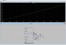
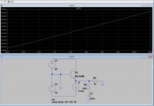
See the attachments.
You can clearly see the change in bias current through the collector with respect to temperature.
http://www.onsemi.com/pub/Collateral/BC546-D.PDF
Look at figure 1 and figure 6 wich shows the current gain and CURRENT-GAIN - BANDWIDTH PRODUCT. You can clearly see that you will move up and down the curve.
Frontend of the diamond buffer can be seen as a source, it is not part of the feedback loop. With an Re of 10R and bias of 2mA you will have an source with an impedance of ~20 - 25R for upper and the lower transistor. This is better than driving next stage directly from a source through a cable.
But i think we can continue this in the CFA thread.
Attachments
Hi Andrej Is this the amending to be done, or is there more meant in that statement from post #2245 qoute "VSSA improvement will be detaily described after all VSSA modules will be shipped out", just curious if D5/D6/R19/R20 are the baby for that improvement, or more is published when shipping is done.Each resistor-diode pair shorten with one wire. By listening tests was confirmed more grip and better bass and even more resolution in mid-high region.
About this D5/D6/R19/R20 shortening do you recommend one to make sound listening test with original setup first, and then do the shortenings with sound listening test to compare. Or is it recommended to jump to shortening setup righting the R19/R20 fast pulse problem in same amend.
- Home
- Vendor's Bazaar
- VSSA Lateral MosFet Amplifier