I was talking of motional feedback compensation, not Zobel (L compensation).
Motional compensation need you measure the -3db frequency points at each side of the resonance peak of the (broke in) speaker.
About Zobel (inductance compensation), it is better to measure too, as Pure L compensation is not flat enough (Eddy currents etc.). Need a more complex circuit than simple rc. Usually an other serial R+C in // with the main C.
But, as i said, it is off topic in this thread, and was just about how to compensate better for not losing damping when bridge operation. Also beneficial, of course with a single mode amplifier.
Think for the moment that reflex loaded enclosures produce two impedance maximums (one at the frequency that reflex port is tuneed at, and the other Fc, resonant frequency of the driver when used in sealed box). How impractical it would be to compensate these two resonances!
Hehe...that's all the magic... No need to.How impractical it would be to compensate these two resonances!
As this compensation network changes the Small and Thiele parametrs, you will constat that it works perfect with compensation of the speaker single free air resonnance. Just you need to tune the resistance in order not to have a hole due to the reflex charge. Of course, you have to calculate your reflex to the ideal frequency resonance (two equal peaks in charge).
Ok, i'm very uncomfortable with this Off Topic, i will open a thread on this .interesting? subject before L.C. kill us all.
Hi i got very interested in this subject, so very very velcome if you will open thread when time allow, cause as you said earlyer it is long explanation.Ok, i'm very uncomfortable with this Off Topic, i will open a thread on this .interesting? subject before L.C. kill us all.
BR Ricky
My VSSA Completed
Hello Folks,
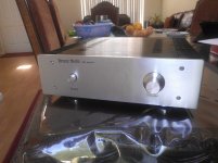
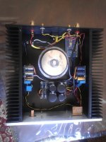
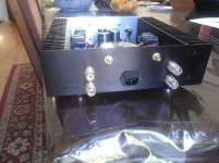
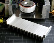
Here are the pictures of my completed VSSA. I went little bit cheap. Amplifier enclosure is from Ebay, as well as the power supply PCB. No preamplifier but a simple 10uf to avoid DC coupling.
It sounds great and living up to the promises made by its creator. Transparent amp ever with solid bass. Even my wife gave the compliments - your amp is awesome. She listens to it most of the day almost every day.
Thanks,
Routhun
Hello Folks,
Here are the pictures of my completed VSSA. I went little bit cheap. Amplifier enclosure is from Ebay, as well as the power supply PCB. No preamplifier but a simple 10uf to avoid DC coupling.
It sounds great and living up to the promises made by its creator. Transparent amp ever with solid bass. Even my wife gave the compliments - your amp is awesome. She listens to it most of the day almost every day.
Thanks,
Routhun
Attachments
Guys you're my friends, I like to read about your audio activities and learn from your knowledge, no worries at all.Ok, i'm very uncomfortable with this Off Topic, i will open a thread on this .interesting? subject before L.C. kill us all.

Hello Folks,
Here are the pictures of my completed VSSA. I went little bit cheap. Amplifier enclosure is from Ebay, as well as the power supply PCB. No preamplifier but a simple 10uf to avoid DC coupling.
It sounds great and living up to the promises made by its creator. Transparent amp ever with solid bass. Even my wife gave the compliments - your amp is awesome. She listens to it most of the day almost every day.
Thanks,
Routhun
Hi Routhun

I like your VSSA amp implementation very very much. It is done very professionally, clear by design and mechanically perfect. Very glad that you like it, it will bring music in a most listenable involving sonic presentation with a lots of details. Thanks for presentation and together with your lady wife have a lot of joy by VSSA.
I was not worried about any lack of friendship from such a gentleman like you...no worries at all.
But the killing ability of the one who design such beautiful 'killing' amps
") !
!Better to concentrate myself on reading comments of builders about the sound of your young but educated baby, to try to understand the reasons leading to similar so good comments (Current feedback operation+ Simplicity ? Quality of active devices, better thermal coupling of power devices due to one case build for the pair ?).
It is obvious you had achieved a real masterpiece and, now, i am curious to understand some of their keys.
Influence of various power supplies (i would love a comparison between your SMPS and a regulated one), if a single SMPS can enhance, as i expect, the stereo image, and if bridged mode can bring quality enhancements in the same time than power increase etc...
I had learned so much, looking at your schematics, and reading at your comments and various tries results. More than during the last two decades.
I see most on the pics of this amp show some pretty sizable heatsinks. Does this amp run so hot that it requires them to be that large? I have been reading through the thread but it is quite large now and I may have missed it.
Thanks, Terry
Terry,
Forum member PMI (great guy!) commented that there is a company in US selling big heatsinks for low prices. It seems that the company is sponsoring this forum, and the name is, if I am not wrong, Heatsink USA. I wish I could buy big heatsink for that low price, so at least for you people living in US, it should not be problem to buy big heatsink. But I guess that smaller heatsink will do for low level listening. This is what I used for through hole version of VSSA amp.
Attachments
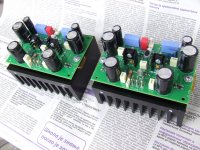
@Terry: I am using the same heatsinks for the modules I have received from LC and for the through-hole version of VSSA. If you buy them as a bare extrusion, they are only about $12.50 each.
At idle, they are barely warm to the touch, about 10-13C rise above ambient, with total current at idle adjusted to about 150mA per channel.
There are several pics in the PeeCeeBee thread, including at the bottom of this post:
http://www.diyaudio.com/forums/solid-state/231662-peeceebee-96.html#post3573462
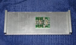
Here is another pic, after machining and w. clear anodize:
At idle, they are barely warm to the touch, about 10-13C rise above ambient, with total current at idle adjusted to about 150mA per channel.
There are several pics in the PeeCeeBee thread, including at the bottom of this post:
http://www.diyaudio.com/forums/solid-state/231662-peeceebee-96.html#post3573462
Here is another pic, after machining and w. clear anodize:
Attachments
Thanks Guys,
The two pics you guys just put up are both way smaller than the sinks I see in LC's case. I was just wondering how hot this amp runs. I still have several heatsinks in my surplus cabinet. How do you think the temps of this amp compare to say a Symasym, Low TIM of P101? I don't mind buying something but if I can used what I have it just makes one thing less to deal with.
Thanks, Terry
Terry,
The heatsink I am using is actually very close to the one LC recommends, 0.5C/Watt, in thermal capacity. About 0.65C/Watt, convection in free air. It is thermally coupled, which actually makes the capacity around 0.45-0.48C/watt (tested).
The heatsink LC is showing pictures of has longer fins (so looks bigger), and not as tall, I believe. It is calculated for pretty much worst case conditions.
So, if you know that you have a heatsink that works for you with a similar class A-B amp, with about the same idle current and supply voltage, it will be good enough.
Pete
You are correct. I did not design the through-hole boards for small sizeMmm, with smaller PCB I think PMI's heatsinks will look BIG, I think LC's are smaller with longer fins
I found another pic for better scale:
edit:
@Terry: Not including the corner brackets, it is 4 x 10 inches, with a 0.3" thick base, and 1" long fins 0.4 inches between fins (if memory serves). I will look it up exactly when I get back home.
Attachments
Last edited:
Hi Pete,
That's fine. I had looked up the heatsinks on Heatsinks USA and saw those. It was hard to tell what size they were from the pics. The heatsinks I used on my Leach are 10"x10" with 2" fins and they get pretty hot after a while. If your sinks are sufficient for this amp, I have a lot of choices from what I have.
Thanks again, Terry
On another note, I have the Antek 5225 transformer, 25-0-25VAC. I this suitable for this amp, two channel? I tried to search back through the tread but couldn't find the optimum size. I am planning to use Pete's PSU boards.
Thanks
Thanks
More than sufficient VA capacity.On another note, I have the Antek 5225 transformer, 25-0-25VAC. I this suitable for this amp, two channel? I tried to search back through the tread but couldn't find the optimum size. I am planning to use Pete's PSU boards.
Thanks
That is the same AC secondary voltage I am using for testing. 25V AC secondary will give you about 36-37V DC, lightly loaded, before the cap multiplier (assuming US 60Hz mains). If you set the power supply for a 1V drop across the pass transistor, +/-35V at the output. For an 8-ohm speaker load, the transformer is almost twice as big as you need, and even with 4-ohm load, still has some headroom.
- Home
- Vendor's Bazaar
- VSSA Lateral MosFet Amplifier