
Watching with great interest. Thanks for sharing your expertise here, Joachim. There is a lot of good general speaker theory in this thread, among the particulars of this design.
btw: jeffb's Satori kit over at Meniscus will be available shortly. They say they are just waiting for the cabinet drawings to be completed.
Troels did a study about stepped baffles:
Stepped Baffle Study
btw: jeffb's Satori kit over at Meniscus will be available shortly. They say they are just waiting for the cabinet drawings to be completed.
Troels did a study about stepped baffles:
Stepped Baffle Study
Yes, wines from France are quite affordable in Germany now. Used to drink wines from Italy a lot but the prices went crazy.
Richi, thanks for that link.
I can already tell you that we need a chamfer in this design. I measured without and with a "fake" chamfer from a metal piece. Off axis it gets even worse.
Will post pictures and measurements later. I do a little break now.
Richi, thanks for that link.
I can already tell you that we need a chamfer in this design. I measured without and with a "fake" chamfer from a metal piece. Off axis it gets even worse.
Will post pictures and measurements later. I do a little break now.

Yes, they are very wide band and that gives a lot of options.
I mentioned before that i will try 2, maybe 3 varieties.
One will be an L/R4 for reference and because it is well established.
The only crossover that is really linear phase is first order but as you say a good approximation can be arrived at with steeper crossovers.
You roll off the tweeter 3rd order and the woofer shallower. There is also the other option to roll the woofer with a higher order Bessel and the tweeter with first order.
I think that was done by Spica. If you accept small frequency response ripples there is a second order option. I think i have seen that on the Music and Design web page.
I have also experimented with inverting the tweeter or the woofer. That also gave some interesting designs. When we go active there is the delay derived crossover or with DSP we have another plethora of possibilities but i would like to stay passive here.
I even thing that a 3rd order Butterworth is not that bad because it does not have a drop in sound power in the crossover region that the LR/4 has.
A problem with phase linear crossovers can be considerably lobing so i am very intested in your measurements, also how they look vertically.
Yes, John Bau made the Spica TC50 using a 4th order Bessel on the woofer and 1st order on the tweeter with an aggressive slope in the cabinet. The problem is that crossover scheme is really tough on a tweeter. I like to give them a little more protection than that, as I am sure you do as well.
And yes, I am very familiar with John K. and the Music and Design website. John and I have discussed these topologies for years and worked together on several design programs as well. He's a really brilliant guy.
Of course, as you know, when you design these crossovers the phase is determined by the final acoustic response of the driver and crossover combined and not just by the circuit itself. So when I talk about the tweeter rolling off 3rd order it has to include the tweeter's natural roll-off too. In reality, below about 600Hz it is rolling off 4th order, but this is far enough out to not impact the crossover behavior too much.
Here's a few measurements you might find interesting. I will probably post a thread on the project on the Meniscus forum soon that will go into more detail.
Here's the frequency response of my kairos speaker on the design axis at one meter in my family room
") , so it won't look like an anechoic response, but I think you will get the idea.
, so it won't look like an anechoic response, but I think you will get the idea. 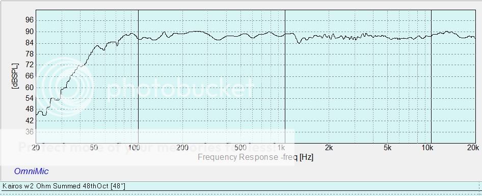
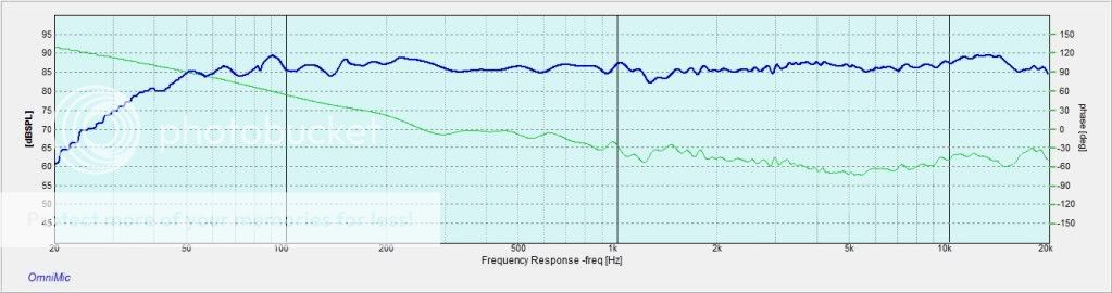
Here's the actual measured phase response (green line) as picked up by the mic at one meter. It isn't transient pefect, but it approximates it fairly well and still offer decent tweeter protection.
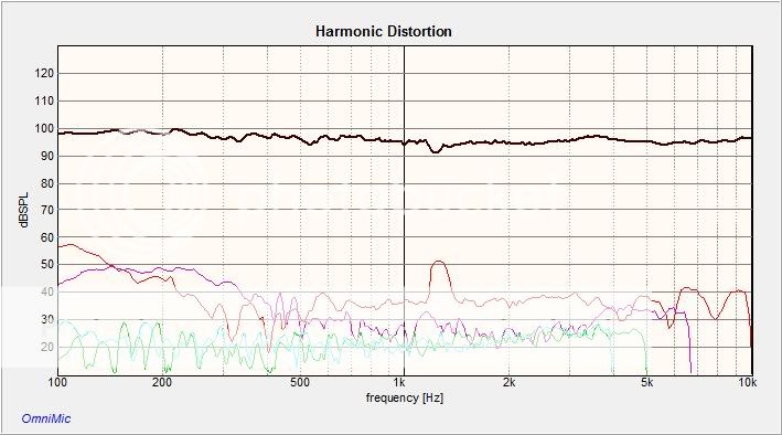
Here's the actual measured distortion above 100hz for the system. It is remarkably low - just that little hic-up at 1200 Hz from the woofer's edge resonance, but these are still excellent results.
Here's another pic. Only this one shows the old one-piece face plate on the tweeter, but it gives a good idea of the speaker's look.
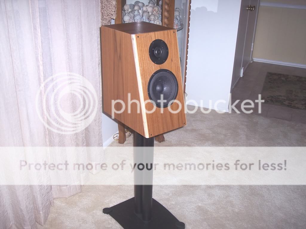
You mentioned the lobing. Of course, with any two driver speaker there will be lobing of some kind, but in this case it is fairly benign because the main null is aimed toward the floor, and another at the ceiling, the window on axis is pretty wide and well-behaved.
It's nice being able to discuss things like phase response with someone who follows my thinking.
Jeff B.
Here's the frequency response of my kairos speaker on the design axis at one meter in my family room
Here's the actual measured phase response (green line) as picked up by the mic at one meter. It isn't transient pefect, but it approximates it fairly well and still offer decent tweeter protection.
Jeff B.
Very nice work!
Are your design axis the same as your tweeter-axis? How will the phase behavior change when you increase the listening distance to 2.5-3m? Do you use the 8 or 4 Ohm version of the Satori mid-woofer?
Sorry for all the questions, but I'm really interesting in other people's findings about this great mid-woofer.
I usually target optimal phase behavior closer to the listening distance, typically 2.5-3m.
Regards
/Göran
I picked these drivers because I will probably use them in diy 3 way floor stand speakers which will have a 10''-12'' woofers ,but price not good option for pioneering.
Thanks for understanding,these are new drivers ,And I couldn't find sufficient informations about them.
Thanks for understanding,these are new drivers ,And I couldn't find sufficient informations about them.
Very nice work!
Are your design axis the same as your tweeter-axis? How will the phase behavior change when you increase the listening distance to 2.5-3m? Do you use the 8 or 4 Ohm version of the Satori mid-woofer?
Sorry for all the questions, but I'm really interesting in other people's findings about this great mid-woofer.
I usually target optimal phase behavior closer to the listening distance, typically 2.5-3m.
Regards
/Göran
I am using the 8 version. My design axis is at the height of the tweeter - my stands are 25" tall. Of course that means the tweeter is off-axis about 14 degrees due to baffle tilt. I found this to be fine since the TW29 has a rsing top octave anyway.
My phase response is measured from the spike of the impluse of the MLS with excess phase removed for time of flight. At other distances it will pretty much look the same, as it will follow the frequency response. In other words if you move off axis, or get far enough away that the top end is dropping then this will be reflected in the phase response as well. Phase and frequency response are intimately tied together in this type of crossover, hence the term "minimum phase response".
Jeff
I don't know if this will be of interest or not, but here is an article I wrote explaining how to determine the relative acoustic offsets between two drivers using simple frequency response measurements and a crossover simulation program. In this version you simply assign the tweeter's acoustic center to be the reference point, even though its exact location may be unknown. Then using this method you can very precisely determine the offset distance between the reference point and the woofer's acoustic center.
As you know, the location of the acoustic center of a driver is not always obvious. For example, for many years it was regard to be the position of the voice coil, so if voice coils were aligned then we had time alignment. Later research found this to not be correct. In most midwoofers the acoustic center is actually very close to the attachment point of the coil former and cone, sometimes, depending on the driver design and how the dust cap is implemented, it can even be forward of this. With dome tweeters it is typically close to the base of the dome.
This method can very easily be used to determing how to offset drivers to exact time alignment and it easier to dial in and read than by viewing the impulse and step response.
Here is a link to a pdf file with the article in it:
https://www.box.com/s/ouxjjsx0m8bs00cil5iq
Jeff B.
Still i would like to see the Step Response.
Thanks for explaining though.
I have a snaphot of that saved somewhere, I've just got to see if I can find it.
- Home
- Vendor's Bazaar
- SB Acoustics Satori Monitor