OPB PCB
If interested add your name to this list.
The amplifier can be found here
http://www.diyaudio.com/forums/solid-state/207746-hal-opb-amplifier.html
If interested add your name to this list.
The amplifier can be found here
http://www.diyaudio.com/forums/solid-state/207746-hal-opb-amplifier.html
2DIFFEF PCB
If interested add your name to this list.
The amplifier can be found here
http://www.diyaudio.com/forums/solid-state/211966-chameleon-mode-2diffef-amplifier.html
If interested add your name to this list.
The amplifier can be found here
http://www.diyaudio.com/forums/solid-state/211966-chameleon-mode-2diffef-amplifier.html
These could also be used
MJH6284G ON Semiconductor | MJH6284GOS-ND | DigiKey
An externally hosted image should be here but it was not working when we last tested it.
MJH6284G ON Semiconductor | MJH6284GOS-ND | DigiKey
Hi OnAudio,If interested add your name to this list.
The amplifier can be found here
http://www.diyaudio.com/forums/solid-state/211966-chameleon-mode-2diffef-amplifier.html
What exactly is the procedure here?
I'd like to build this amplifier.
Chris
Hi OnAudio,
What exactly is the procedure here?
I'd like to build this amplifier.
Chris
Your Free to start a group buy. Drowranger was preparing a PCB. If his isnt ready will prepare one .
")
How to attach the output transistors
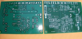
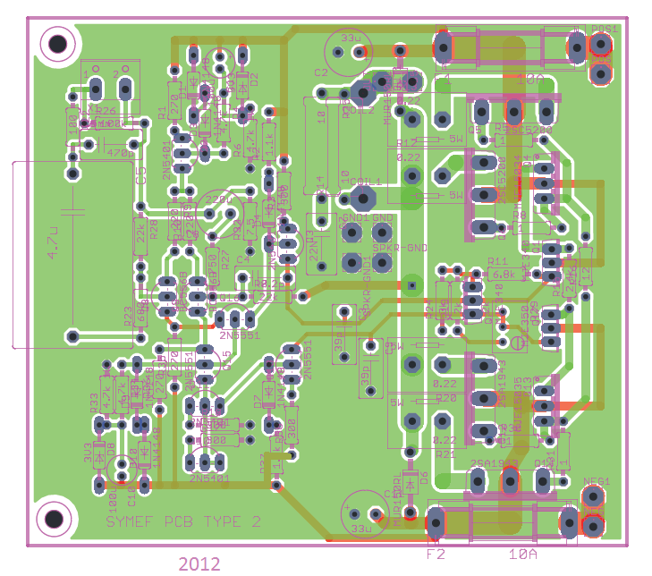
My SYMEF type 2 PCBs arrived and look great. Thanks HAL. They seem the same as this draft, at least regarding the orientaion of the output transistors.
I am puzzled however with the orientation of the output transistors. How do I attach them to the heatsink and get the leads in the right PCB orientation as shown.
I'll appreciate an explanation; picture would be even better.
Thanks,
Francois
[/URL]
My SYMEF type 2 PCBs arrived and look great. Thanks HAL. They seem the same as this draft, at least regarding the orientaion of the output transistors.
I am puzzled however with the orientation of the output transistors. How do I attach them to the heatsink and get the leads in the right PCB orientation as shown.
I'll appreciate an explanation; picture would be even better.
Thanks,
Francois
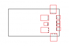
1. Place unpopulated PCB on heat-sink.
2. Use ink to mark the lead positions on the heat-sink.
3. Place transistors on heat sink with the pins bent straight up
4. Align the transistors leads with the ink marks
5. Use ink to mark the mounting holes of each transistor
6. Drill mounting holes
7. Mount transistors
8. Populate PCB
9. Place PCB over transistors
10. solder the transistors
Last edited:
The link to the BoM appears to have changed (due to thread moving?). Be grateful for another link as my mac seems to have lost (which is my fault) the original download!!
Can you perhaps point me in the right direction? Mainly interested in BoM for latest boards.
Many thanks,
B
EDIT: just found the latest revision in .pdf format, but it will not open (for me) on Mac 10.7.5.
Can you perhaps point me in the right direction? Mainly interested in BoM for latest boards.
Many thanks,
B
EDIT: just found the latest revision in .pdf format, but it will not open (for me) on Mac 10.7.5.
Last edited:
- Status
- This old topic is closed. If you want to reopen this topic, contact a moderator using the "Report Post" button.
- Home
- Vendor's Bazaar
- Combined Onaudio thread. (23 threads)