This version use USB or RS232 interface communication with PC.
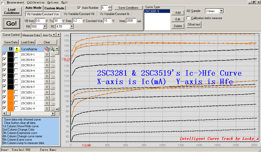
It can measure BJT's Ic->Hfe curve
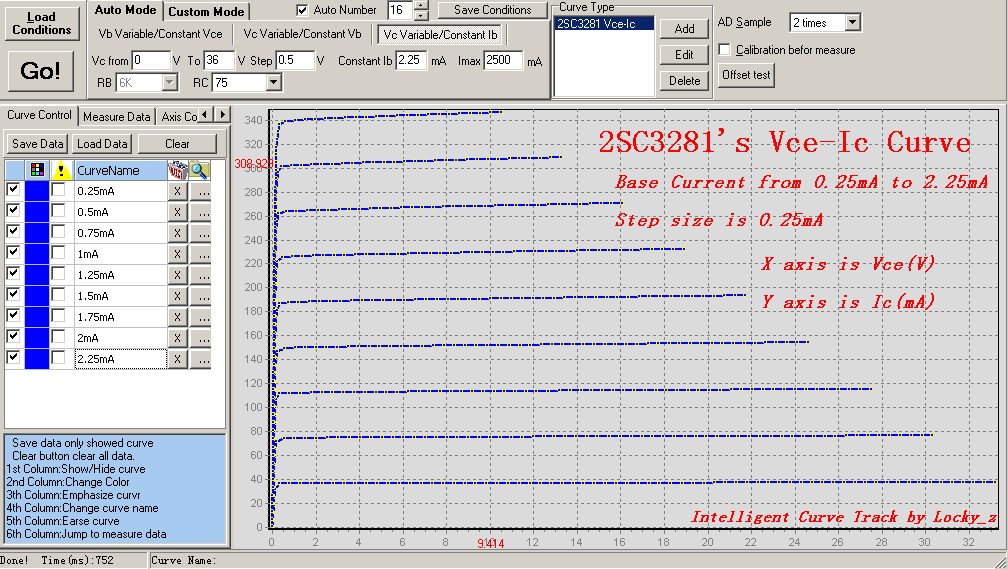
Can measure Vce-Ic curve
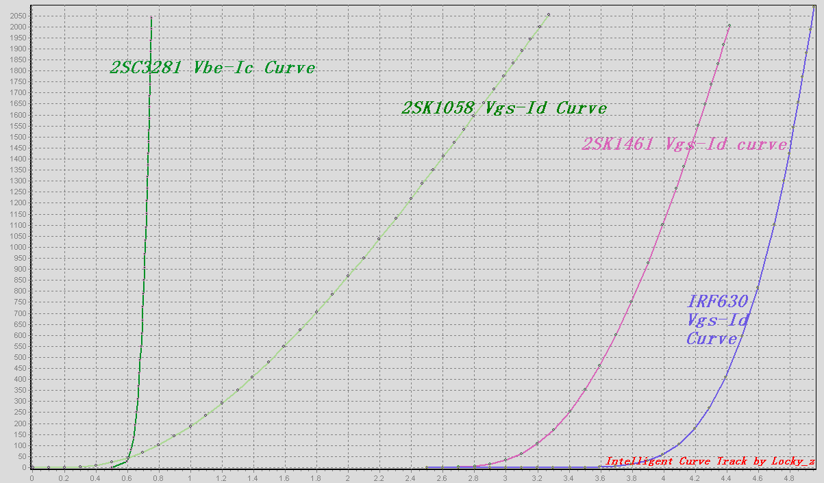
measure some semiconductor transmission curve,such as Vbe-Ic / Vgs-Id
also FET’s Vds-Id curve measure,Even can study Vgs & Rds relationship
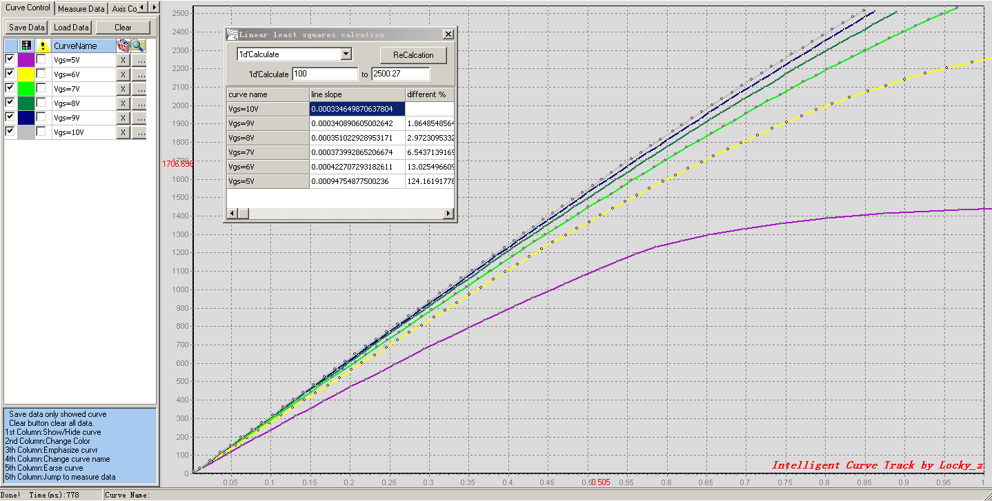
Upper is six IRF630 Vds-Id curves,their Vgs is 5V 6V 7V 8V 9V 10V.
The Vds-Id curve only show Vds=0~1V range,so you can use system’s calculate function get the slope value,
The window in the central show six curve’s slope, Measurement unit is V/mA, multiplicate 1000 is Rds,
So under Vgs=10V,Rds is 0.000334649870637804*1000=0.334ohm
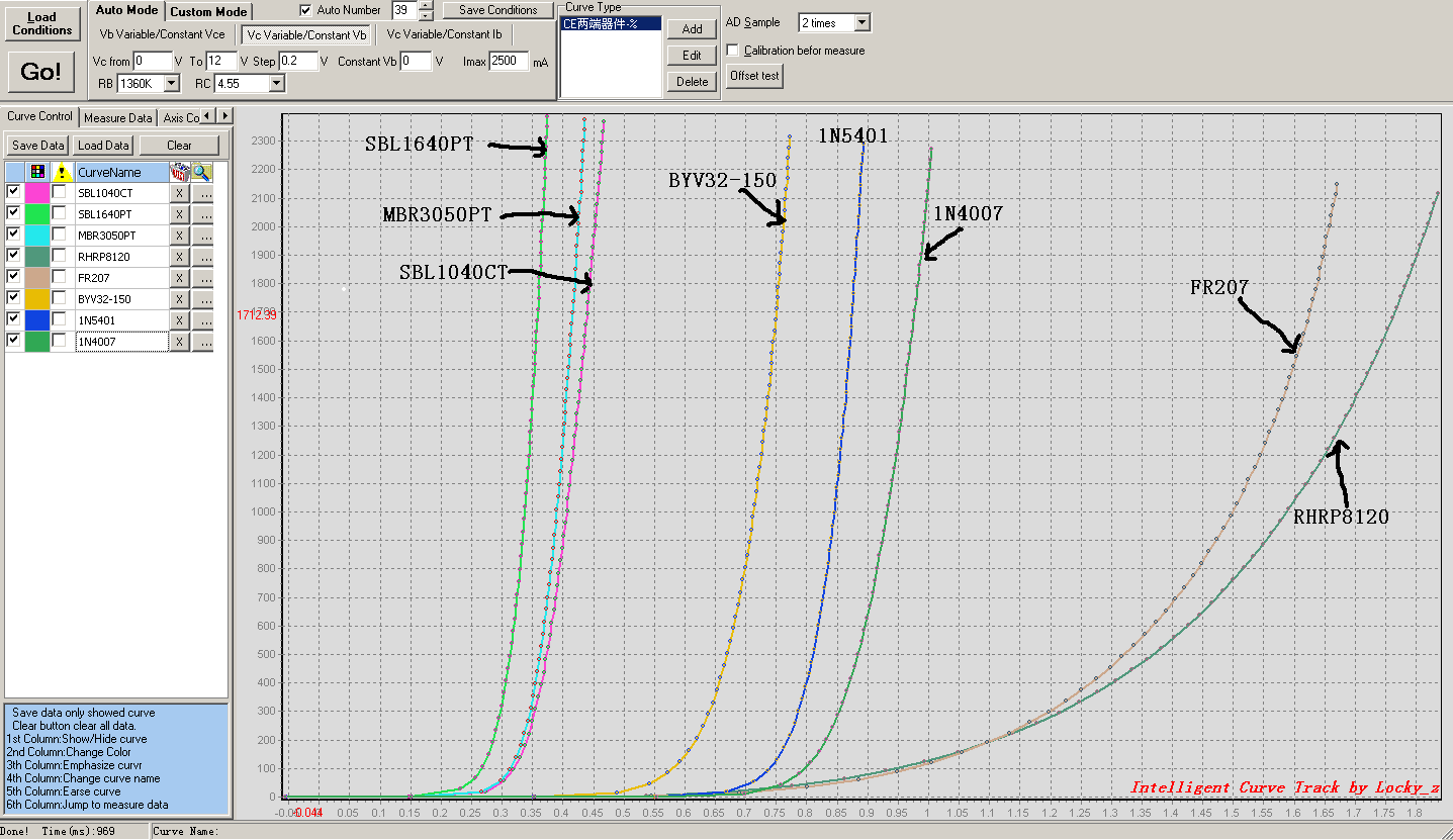
Some diode V->I curve
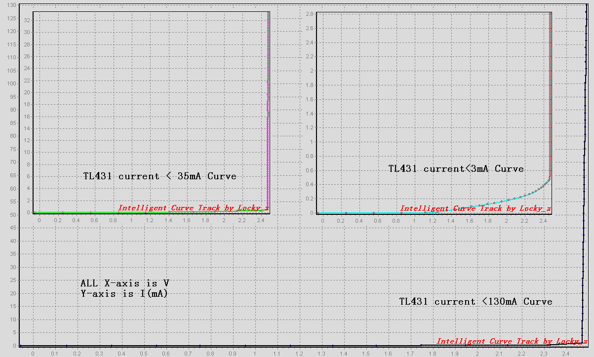
fllower is TL431 in all current range V-I curve
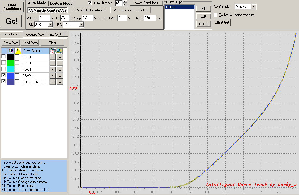
if you plug TL431 into socket B and E,and change the measure condition,you can see less current VI curve. The following figure , Y-axis is only 0~0.38mA
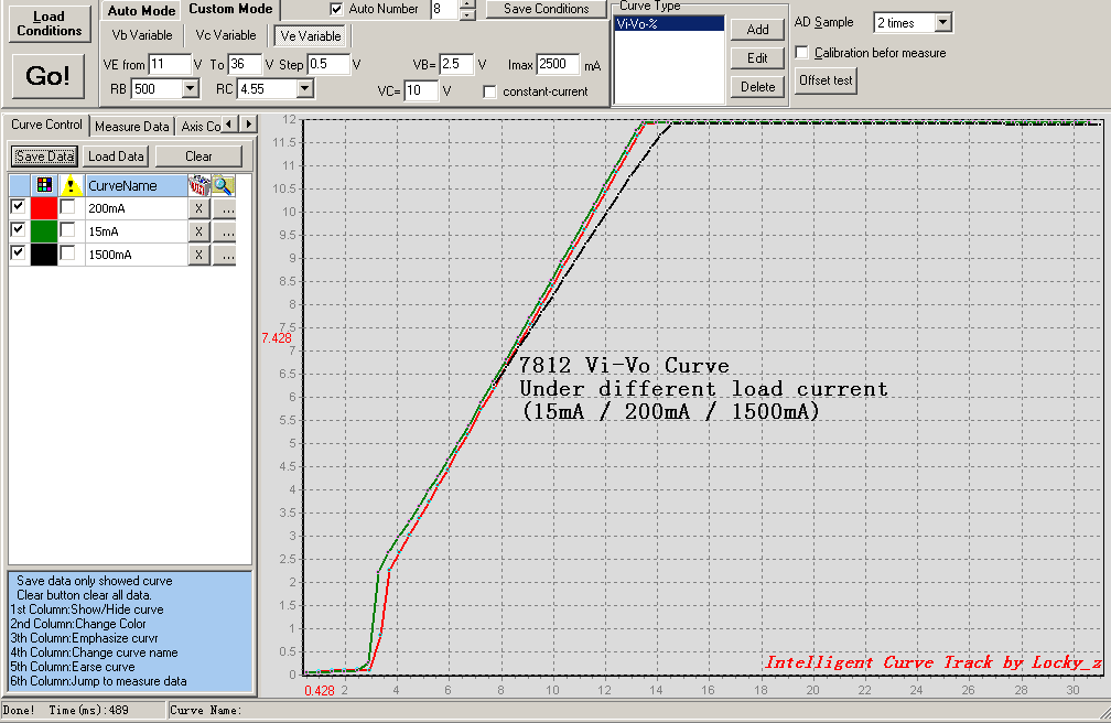
the Intelligent Curve Tracer is more powerful,It can measure 3 terminal voltage regulator’s Vi-Vo / Io->Vo Curve
It can measure BJT's Ic->Hfe curve
Can measure Vce-Ic curve
measure some semiconductor transmission curve,such as Vbe-Ic / Vgs-Id
also FET’s Vds-Id curve measure,Even can study Vgs & Rds relationship
Upper is six IRF630 Vds-Id curves,their Vgs is 5V 6V 7V 8V 9V 10V.
The Vds-Id curve only show Vds=0~1V range,so you can use system’s calculate function get the slope value,
The window in the central show six curve’s slope, Measurement unit is V/mA, multiplicate 1000 is Rds,
So under Vgs=10V,Rds is 0.000334649870637804*1000=0.334ohm
Some diode V->I curve
fllower is TL431 in all current range V-I curve
if you plug TL431 into socket B and E,and change the measure condition,you can see less current VI curve. The following figure , Y-axis is only 0~0.38mA
the Intelligent Curve Tracer is more powerful,It can measure 3 terminal voltage regulator’s Vi-Vo / Io->Vo Curve
Attachments


Intelligent Curve Tracer Principle
Before talking about my Intelligent Curve Tracer principle,I talk about the general measure curve principle by MCU first.
The general measure diagram as in Figure
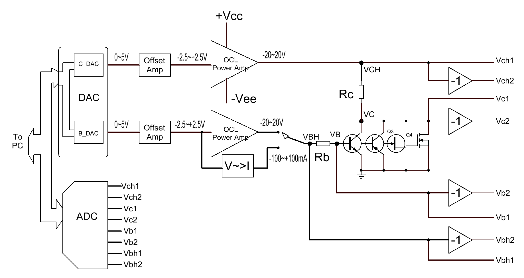
Mcu control Channel B/C DAC and OCL power amplifier to driving the DTU, And measure four voltage(VBH/VB/VC/VCH) by ADC, and then calculate the Ib/Ic/Vce/Vbe and then draw the Vbe-Ic/Vce-Ic/Ic-Hfe curve.
Because of the need for the measure of P and N type semiconductor,so all the voltage are bipolar.
But considering the component selection, Most of the DAC and ADC can only output or measure unipolar voltage,bipolar ADC price will be very expensive.
Considering the cost of it, it uses unipolar ADC/DAC a lot cheaper, choice scope is much extensive.
So if we use unipolar ADC/DAC to design the curve tracer,we need some additional circuit:
1.four amplifier,It’s gain is –1, purposes to change negative voltage to positive voltage,so that the ADC can handle.
2.two amplifier to offset DAC to bipolar voltage;
3.Need biporlar power supply, but the DTU’s vce voltage range is only half of the total supply voltage;
4.Need 8 channle ADC to measure vbh1/vbh2/vb1/vb2/vch1/vch2/vc1/vc2;
My intelligent Curve Tracer in the above principle to make an improved, Using the" three voltage amplifier to drive DTU, the DTU emitter isn’t connect to ground, but from a voltage source,.
the following diagram principle:
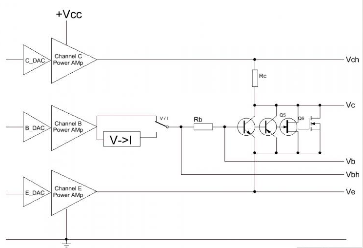
The emitter voltage source(Channel E Power Amp) is very critical, completely solve the shortcomings of the above,.
for example
Measure NPN BJT,We set Channel E Power Amp to output 2.5V, and set Channel B/C Channel power amplifier to output more then 2.5V,such as B channel is 5V, C channel is 20V,so the NPN can work. We measure the Ve/Vbh/Vb/Vc/Vch then calculate the Vbe/Vce/Ib/Ic/Hfe and draw the curve.
If measure PNP BJT,We set Channel E to output 40V, and set Channel B/C Channle to output less then 40V,so PNP can work. We also measure the Ve/Vbh/Vb/Vc/Vch then calculate the Vbe/Vce/Ib/Ic/Hfe and draw the curve.
If measure N type J-FET,We connect JFET’s source to E, grid to B, Drain to C. and set E channel output 10V,and set B Channel is from 2.5V to 10V, and set C Channel output from 10 to 40V. This means that the JFET’s Vgs is –7.5 to 0V,and Vds is from 0 to 30V. This is the JFET normal operating voltage range.
You look back above example, All the measure voltage are unbipolar,so DAC and ADC are just use a unipolar model device.
And the solution only need a 40V unbipolar power supply, and the DTU Vce range can be from 0 to 40V.
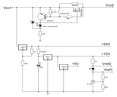
2.power supply and protect circuit
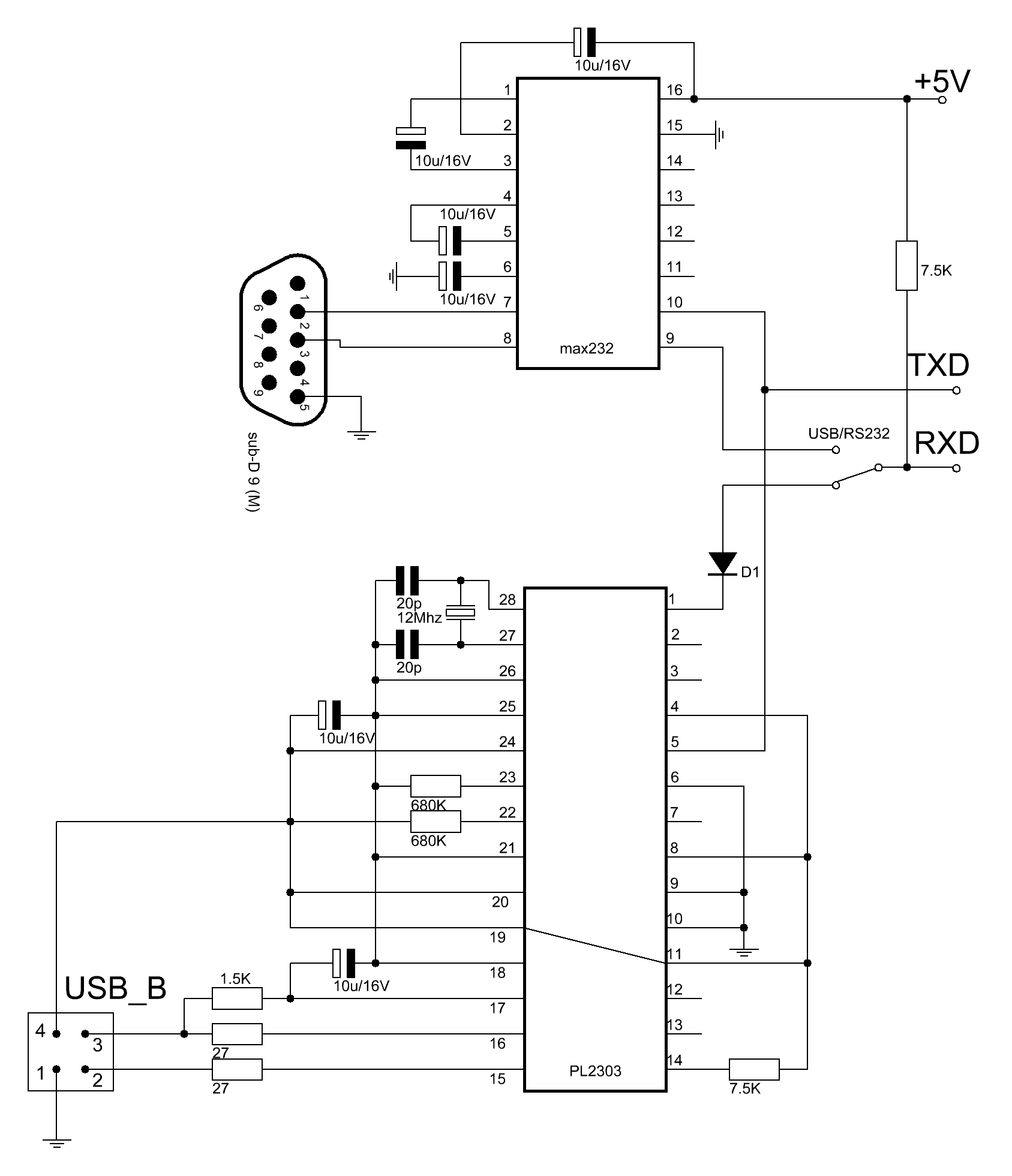
3.USB and RS232 interface circuits
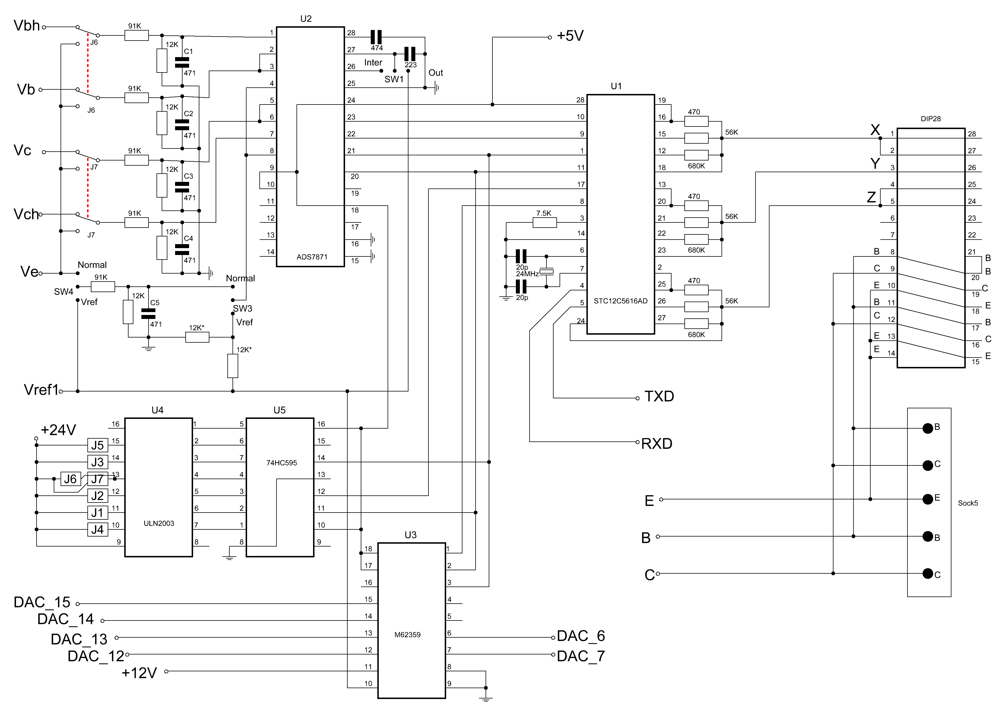
4.MCU & ADC & DAC & Control circuit
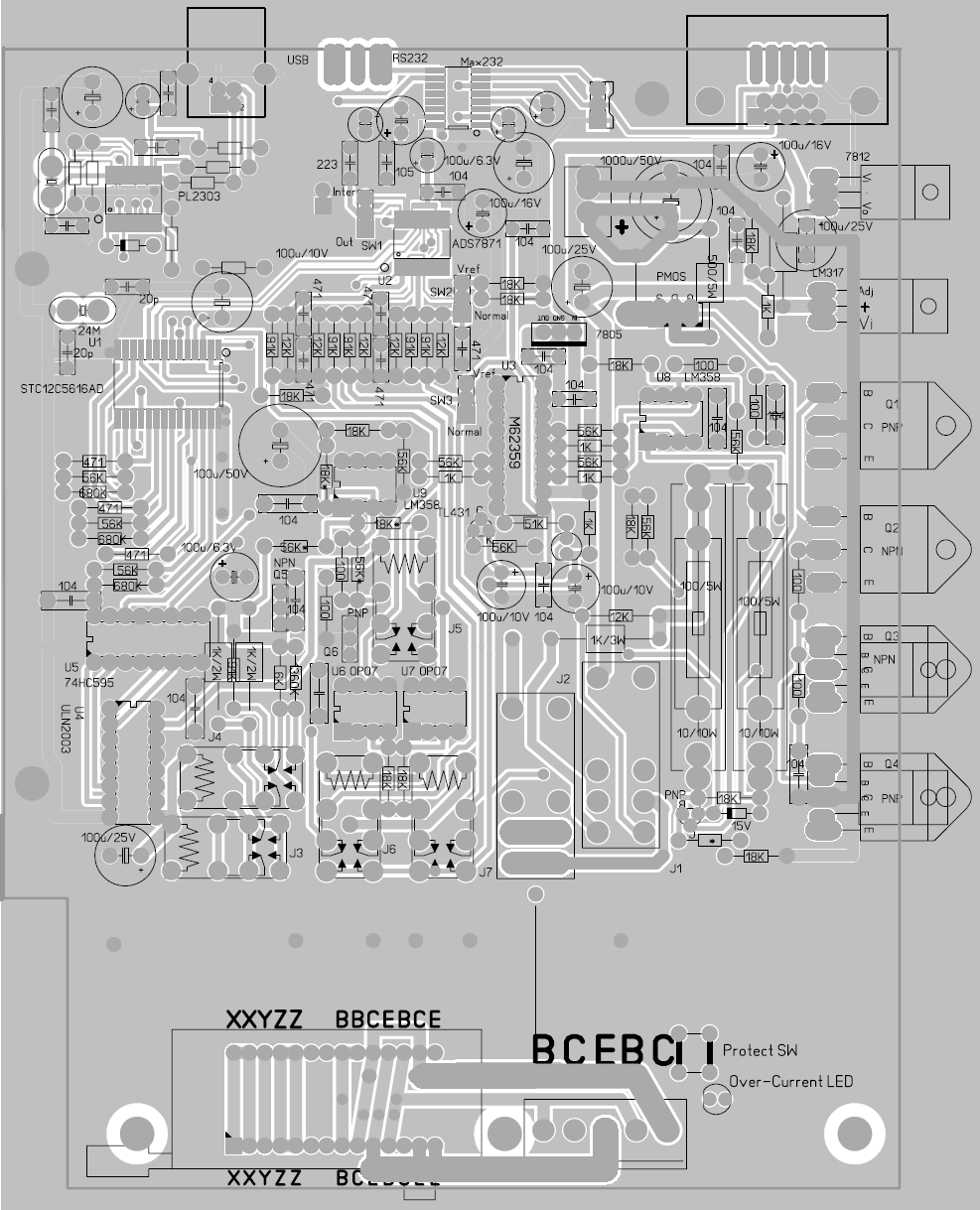
5 PCB
Before talking about my Intelligent Curve Tracer principle,I talk about the general measure curve principle by MCU first.
The general measure diagram as in Figure
Mcu control Channel B/C DAC and OCL power amplifier to driving the DTU, And measure four voltage(VBH/VB/VC/VCH) by ADC, and then calculate the Ib/Ic/Vce/Vbe and then draw the Vbe-Ic/Vce-Ic/Ic-Hfe curve.
Because of the need for the measure of P and N type semiconductor,so all the voltage are bipolar.
But considering the component selection, Most of the DAC and ADC can only output or measure unipolar voltage,bipolar ADC price will be very expensive.
Considering the cost of it, it uses unipolar ADC/DAC a lot cheaper, choice scope is much extensive.
So if we use unipolar ADC/DAC to design the curve tracer,we need some additional circuit:
1.four amplifier,It’s gain is –1, purposes to change negative voltage to positive voltage,so that the ADC can handle.
2.two amplifier to offset DAC to bipolar voltage;
3.Need biporlar power supply, but the DTU’s vce voltage range is only half of the total supply voltage;
4.Need 8 channle ADC to measure vbh1/vbh2/vb1/vb2/vch1/vch2/vc1/vc2;
My intelligent Curve Tracer in the above principle to make an improved, Using the" three voltage amplifier to drive DTU, the DTU emitter isn’t connect to ground, but from a voltage source,.
the following diagram principle:
The emitter voltage source(Channel E Power Amp) is very critical, completely solve the shortcomings of the above,.
for example
Measure NPN BJT,We set Channel E Power Amp to output 2.5V, and set Channel B/C Channel power amplifier to output more then 2.5V,such as B channel is 5V, C channel is 20V,so the NPN can work. We measure the Ve/Vbh/Vb/Vc/Vch then calculate the Vbe/Vce/Ib/Ic/Hfe and draw the curve.
If measure PNP BJT,We set Channel E to output 40V, and set Channel B/C Channle to output less then 40V,so PNP can work. We also measure the Ve/Vbh/Vb/Vc/Vch then calculate the Vbe/Vce/Ib/Ic/Hfe and draw the curve.
If measure N type J-FET,We connect JFET’s source to E, grid to B, Drain to C. and set E channel output 10V,and set B Channel is from 2.5V to 10V, and set C Channel output from 10 to 40V. This means that the JFET’s Vgs is –7.5 to 0V,and Vds is from 0 to 30V. This is the JFET normal operating voltage range.
You look back above example, All the measure voltage are unbipolar,so DAC and ADC are just use a unipolar model device.
And the solution only need a 40V unbipolar power supply, and the DTU Vce range can be from 0 to 40V.
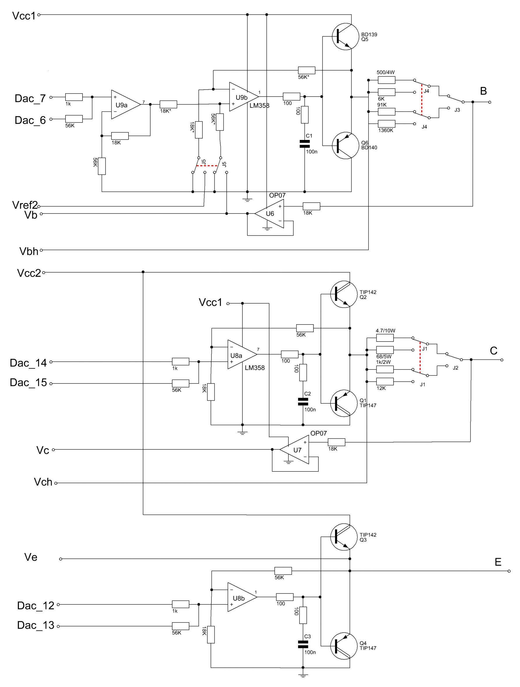
Actual circuit
1.three channel power amplifiers2.power supply and protect circuit
3.USB and RS232 interface circuits
4.MCU & ADC & DAC & Control circuit
5 PCB
Attachments


Last edited:
Very good job!!!
What are the max Vce/Vds and Ic/Id that can work?
I will measure also the newer Sic Power Jfet, the SIT and the old V-fet. 😀😀😀
Let me know.😎
I want buy it as finite and complete product.
Ebay or Paypal is possible?
Thanks, Francesco.
What are the max Vce/Vds and Ic/Id that can work?
I will measure also the newer Sic Power Jfet, the SIT and the old V-fet. 😀😀😀
Let me know.😎
I want buy it as finite and complete product.
Ebay or Paypal is possible?
Thanks, Francesco.
Good work! It would be interesting to have additional interface connections to allow for a higher voltage driver circuit to use for testing vacuum tubes. It might be worthwhile to be able to generate stepped control for the screen grid also. Some curves that people usually do not see, like transconductance versus screen voltage could also be possible. It might help people know how much to vary the screen voltage of one tube to balance in a pair with another that does not match. Some might consider advanced options like sweeping the curves for one tube, have them in memory, then additionally stepping the screen voltage on a second tube to find the closest match. The common practices of matching gain at one bias value with a tube tester, and adjusting amplifier bias for equal idle current works poorly. A great improvement in matching and in selection of settings to compensate for mismatch is possible with more advanced testing.
max Vce+Vrc is only 36V. mean DUT's Vce add the voltage drop of current sampling resistor must less 36V,What are the max Vce/Vds and Ic/Id that can work?
I will measure also the newer Sic Power Jfet, the SIT and the old V-fet. 😀😀😀
Example,
If you current is 2A ,and current sampling resistor select 4.5ohm,then
max Vce is only 36-2*4.5=27V.
But if you measure JFET,the absolute(Vgs) + Vds + Vrc must less 36V,
Example: if you set Vgs is -5V, current is 2A,and sampling resistor is 4.5ohm
then max Vds is 36-5-2*4.5=22V.
The device sell link
Wholesale Intelligent Curve Tracer
On ebay,I has been registered,but can‘t sell,because ebay can't let me to 'go through an additional verification step' (需通过eBay跨国交易手工认证).
And aliexpress and ebay is 'competitive relation'.So aliexpress can't use palpay after 2011.08.
Last edited:
It would be interesting to have additional interface connections to allow for a higher voltage driver circuit to use for testing vacuum tubes. .
This can't measure tube,bucause the scheme not suit high voltage.
but 2 years ago,I had development some tube curve tracer.
Two anode/cathode/grid voltage Generator and high side current measure board

measure 6N13(Chinese tube)

Set grid voltage as -90/-85/-80/-75/-70/-65/-60/-55/-50/-45/-40/-35/-30/-25/-20/-15/-10/-5V and measure the plate voltage->Plate current curve.

The 6N13 transmission curve in different anode voltage,the anode voltage is 25/50/75/100/125/150/175V

the 6N12(double tube) transmission curve,Objective to understand the degree of match

but the tube curve precision not enough at low grid-cathode voltage,
you can compare 6N12 transmission curve and 6N13 transmission curve,
the 6N13 is more smooth,becasue 6N13 grid-cathode voltage is more high.
Tube curve tracer had termination.
Are there any additional taxes in China, when sell to outside or the shipping cost to Europe is to high?
I see at Taobao a price of 560 CNY...almost 88$ US and at Wholesale a price of 229$US
I see at Taobao a price of 560 CNY...almost 88$ US and at Wholesale a price of 229$US
Are there any additional taxes in China, when sell to outside or the shipping cost to Europe is to high?
I see at Taobao a price of 560 CNY...almost 88$ US and at Wholesale a price of 229$US
The additional is freight / Trading platform fee / Cash withdrawal fee /
You can find the cost to China from the United States send 3Kg of cargo. Estimated from China to the United States is nearly.
The 'Trading platform fee' on Ebay of China is 6~7%,Aliexpress nearly.
The 'Cash withdrawal fee' of Palpay of China is $35,Aliexpress nearly.
May be have some Customs Tariff.
Can you sell the kit without the box ? it might be cheaper for DIYAUDIO members to buy( particularly from US ) avoiding excessive shipping costs etc?
kannan
kannan
Locky, my curve tracer arrived last day.
I have connected it to pc with serial interface RS232. Then, in menù configruration parameter, i have selected "Autodetect" and the answer was "DEVICE NOT FOUND".
I have checked the switch was in RS232 mode. My power line is 220 AC, I am not able to view if power is "ON" because no led installed, but the wires from AC plus was ok. So I i tell you "because the device not respond?"😕
I not get program association for the .PRE extension file. My O.S. is Windows XP
Thanks much, Francesco.
Last edited:
Out Box LED is Overcurrent protection indicator,It always not bright.
The Power LED indicator inside Box.
You can use some wire connect slot X Y Z,and power on, and you will hear 8~9 relay voice,this mean the MCU is OK.and the communication rate will auto set to 28800bps.
And then you run software, press 'Autodetec'
the .pre extension file is save the 'Measurement conditions' file,you can use notepad to open.
 Thread moved to vendors bazaar due to commercial interests.
Thanks, I thought I could ask my friend to buy a complete unit for me instead of waiting for the GB 🙂

1.You use RB=500ohm ? It could make Ib too large,and lead to Vce too small,and measure process will termination.
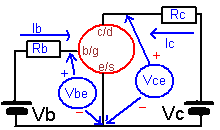
If you understand this measurement schematic, you will understand that the choice of the RB the RC and Vb range
Generally small single transistor measure is using RB=1360K or RB=91K and RC=1K.
another you check DTU pin.
If you understand this measurement schematic, you will understand that the choice of the RB the RC and Vb range
Generally small single transistor measure is using RB=1360K or RB=91K and RC=1K.
another you check DTU pin.
Attachments

Last edited:
Will the software permit the acquisition and then later comparison of a number of curves, each of a different device under test?
What would happen if a user was to add an external DC amplifier )x10 ?) to increase the range of the collector voltage and then scale the measurement resistor to suit? (Vc)
Do you have over voltage protection on the measurement ("input") terminals so that things will not burn out in the event of excess voltage being present?
Regards,
_-_-bear
Last edited:
Because the resistor in different device maybe not match,so the result is different device may different,but the different is tiny.
Example measure hfe, in a device is hfe=100,but in another device maybe hfe=101.5, Because their The divider resistor and current sampling resistor may be not exactly the same.
The intelligent Curve Tracer not suitable for high voltage measure, and hard to increase range.
There are no over voltage protection,because the device not know what DTU is measuring,
It just follow your setting measurement conditions and the output voltage(max is 36V)
It had only the hardware of overcurrent protection.It only protect the Curve Tracer,can't protect the DTU.
- Home
- Vendor's Bazaar
- Intelligent Curve Tracer 3.0 release