locky_z
It would seem to me that a "crowbar" circuit or a Zener, or maybe a transzorb would protect sensitive input circuits?
Also I don't quite understand why the input to the tracer's current or voltage sense can't be scaled, the easiest being a simple divider, more complex with an external active circuit, and the collector voltage scaled with a DC amplifier?
Are you saying it won't work because you are not using ground on the "emitter" side?
_-_-bear
1.It use a op as follower,so it only operate at 40V.
2.It use differential amplifier and differential measurement,It requirements of high resistance matching degree, and I use calibration reduce the impact,
but if series resistor voltage divider too much, measure P type DTU will have error
My English level is low,and don't unstander what is mearn:
‘It would seem to me that a "crowbar" circuit or a Zener, or maybe a transzorb would protect sensitive input circuits?’
1.It use a op as follower,so it only operate at 40V.
2.It use differential amplifier and differential measurement,It requirements of high resistance matching degree, and I use calibration reduce the impact,
but if series resistor voltage divider too much, measure P type DTU will have error
My English level is low,and don't unstander what is mearn:
‘It would seem to me that a "crowbar" circuit or a Zener, or maybe a transzorb would protect sensitive input circuits?’
Ok.
To keep from damage
To keep from breaking
To protect
To make maximum voltage not go too high
For test input voltage.
A circuit can be used for this
For this a Zener can keep voltage below
A "tranzorb" part will CLAMP maximum voltage
OR a circuit using a triac or SCR can be triggered at a maximum voltage
So no worry that too much voltage can destroy ADC or opamp.
IF I want to use unit for 200volt Vce, can not.
But If I use 10x DC opamp for Vce then I get 40vdc x 10 = 400vdc
But this is too much voltage for ITC 3.0
So, I want to use a circuit to make:
- test voltage higher (5x or 10x)
- scale, divide or adjust current sense back to ITC 3.0 regular 0-36vdc range when transistor is being tested This is 5x or 10x lower than actual voltage tested.
- it will display as 0-40 volt but will be higher!
Now ITC 3.0 "thinks" it is testing in regular range, but is really testing 5x or 10x more collector voltage
_-_-bear
Last edited:
The curve tracer 3.0(CT3) have no high voltage protect because it not allowed outside measure voltage and can't measure outside input voltage.
The curve tracer 3.0(CT3) have 3 channel voltage generator inside ,It only handle less 40V.
If you replace the voltage generator,let it to output 100V,and change the divide scale of ADC, the CT3 can work more high voltage.
but another thing is you need a DC fllower that it can work under high voltage,the fllower is use to increasing the input impedance, without affecting the base current. but high voltage fllower not exist.
Figure 6 of this TI Application Note will give you some idea how to do high voltage with an opamp :
http://www.ti.com/lit/an/snoa600a/snoa600a.pdf
Just take it as a friendly advice, as were all the advices we gave you a couple of years back.
Patrick
http://www.ti.com/lit/an/snoa600a/snoa600a.pdf
Just take it as a friendly advice, as were all the advices we gave you a couple of years back.
Patrick
I had research some 'Op booster' cricuit,They are not difficult.Figure 6 of this TI Application Note will give you some idea how to do high voltage with an opamp :
http://www.ti.com/lit/an/snoa600a/snoa600a.pdf
Just take it as a friendly advice, as were all the advices we gave you a couple of years back.
Patrick
But a difficult thing is the fllower, It need work in single supply, and Vicomm range need Vee+2~ Vcc-2,if use Op+booster,It is hard to do.
if use discrete component to make a single supply high voltage fllower,but It is difficult to guarantee the DC characteristics.
I am sure you are aware that :
a) your DAC output would never be 120V, so you need a gain stage after that with negative feedback to reach high voltage;
b) there are many rail-to-rail opamps around that will output very close to the negative rail;
c) it is easy enough to make that circuit in Fig 6 single ended;
d) you are neither worried about distortion nor about high slew rate.
Best,
Patrick
I can only guess that by follower you mean an output stage that can source or drain current, and NOT unity gain.
There is no need to use unity gain, as you already mentioned earlier.
If that is the case I do agree with you it is not so easy to make a single ended output stage that can both source and drain current.
But I do not think it is necessary to do so in this particular application.
For testing any MOSFETs and BJT's, Vce or Vds of +/-30V is sufficient for most purposes.
So people who want 100V want to use the Curve Tracer for Tubes.
But Tubes only have "N" types and no "P" types.
So you can make, as an adaptor to your current PCB, a HV current source with an opamp and 2 transistors (1x N-Mosfet small signal and 1x P-Mosfet power) for your C-channel only. You can still use your E-channel to drain the current.
I do not think you need HV for your B (or gate) channel, but then I am not a tube guy.
Patrick
There are not need E-channel AMP if only N type(or Tubes) be measured, direct use GND replacement E channel. This may Easy to designed,
Because P type need measure, so I add E-Channel AMP to drive the Emitter/Source.
The follower inrder to measure two voltage:Vb and Vc
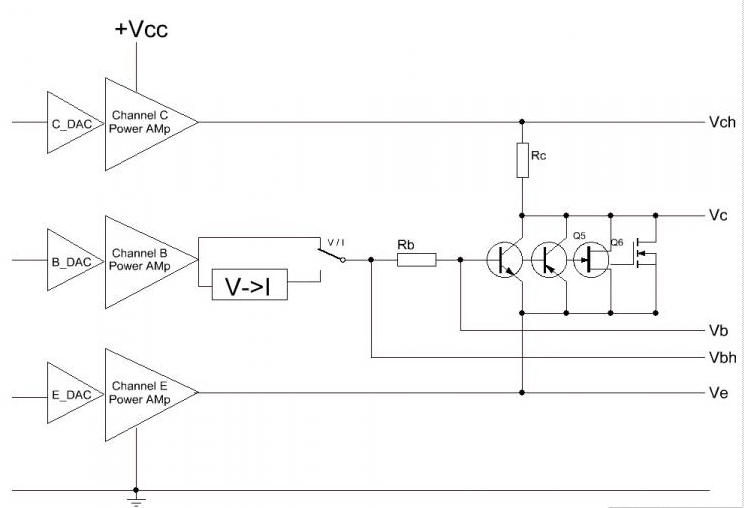
if Simple parallel resistance at Vc and Vb to GND,they may shunt the Ib and Ic,so measure may have error.
Because Vb and Vc's voltage swing is same as Power Amp output voltage swing,
The Power Amp output voltage swing is Gnd+2 ~ Vcc-2V,
If power supply less 40V,then direct use OP07 as follower,
If power supply more then 40V,It is hard to design the follower.
Because P type need measure, so I add E-Channel AMP to drive the Emitter/Source.
The follower inrder to measure two voltage:Vb and Vc
if Simple parallel resistance at Vc and Vb to GND,they may shunt the Ib and Ic,so measure may have error.
Because Vb and Vc's voltage swing is same as Power Amp output voltage swing,
The Power Amp output voltage swing is Gnd+2 ~ Vcc-2V,
If power supply less 40V,then direct use OP07 as follower,
If power supply more then 40V,It is hard to design the follower.
Last edited:
Firstly let's see if we agree that we only need to measure tubes at > 100V.
If we do not agree, then I rest my case.
If we agree, then this is how I would do it with your current hardware :
1) Connect the cathode of the tube to the C-channel. Set Vch to say 12V.
2) Connect the grid to the B-channel. This will allow a negative grid voltage up to -10V relative to cathode. B-channel in voltage mode.
3) Connect the E-channel to an opamp driving an output stage as described in post#29. The E-channel rail can be as high as the Mosfets will take.
You need to change some software, but you can now measure current (inverted) using Rc. And Grid voltage is, if I am not wrong (I checked Linsley Hood's books just now) always negative to cathode. So measuring grid voltage to cathode is no problem.
But perhaps some tube guy will tell you whether I am talking nonsense.
Patrick
No, I want to measure transistors out to over 200v for some applications.
It is good to see where the breakdown voltage is in a given batch, especially if you are forced to work near the rated limits. Nice if you don't, but if you do... this happens often enough in high power amplifiers...
My Tektronix and Fairchild units will do 400vdc and 1000vdc respectively, which is fine.
Of course they do not "remember" anything, since they just do simple curve tracing.
The Tek can switch between two DUTs, but that too has it's limits.
What would be best is to be able to "slam" devices into a ZIF socket, quickly, push a test button, repeat, repeat, etc... and have all the curves recorded. Then put some parameters into a screen and have the results sorted by those parameters - the devices number being the order tested. So now I can just grab the devices according to the computer's sort by pulling the right numbers and have batches of matched devices!
That's the idea as far as I am concerned. If I have to look at the curves to compare devices, then I personally don't need a computer based curve tracer at all.
_-_-bear
Last edited:
Most Tube is like N type J-FET in normal voltage, but if work in low voltage,Tube like some BJT.
I had used CT3 to test some Tube in low Cathode-Anode voltage.
but under low Cathode-Anode voltage,Even if the gate voltage is 0, Most tube have no anode current.
you must give gate positive voltage,the tube will have some current,and the Gate current almost equal anode current.
Because High voltage and No P Type ,So this Intelligent Curve Tracer circuit not suit Tube test.
I plan designed another circuit to test Tube,Of course It will be considered to A2 and AB2 state, and measure the Anode current ,gate current and screen grid current.

Looking at the design a little more.
Why not make "C" amp run from + & - rails??
Put an inverter at the input for switching from Nch to Pch??
Put an inverter at the input of the Bch amp too??
If the input to both amps only runs in one polarity, then the output is only in one polarity?
Is there a reason not to do this?
I would think this is exactly the sort of thing that previous commercial curve tracers had to do?
Of course I am completely unclear on how one is supposed to operate the IT 3.0, but surely would like a DIY sort of unit that is computer controlled that can do batch testing with software sorting of the results.
_-_-bear
I was able to view only the output curves of NPN Bjt, but not for PNP Bjt.
Also i cannot view the curves for Jfets. Your manual is not detailed enough.
Can you advice me for that?
Francesco
You load 'PNP Vce-Ic' condition
and plug PNP in slot, Base insert B,Collect into C,Emitter into E,
and press 'GO!' button.
JFET is the same,load 'measure continue' and plug Gird into B,Source into E,Drain into C.
Looking at the design a little more.
Why not make "C" amp run from + & - rails??
Put an inverter at the input for switching from Nch to Pch??
Put an inverter at the input of the Bch amp too??
If the input to both amps only runs in one polarity, then the output is only in one polarity?
Is there a reason not to do this?
I would think this is exactly the sort of thing that previous commercial curve tracers had to do?
Of course I am completely unclear on how one is supposed to operate the IT 3.0, but surely would like a DIY sort of unit that is computer controlled that can do batch testing with software sorting of the results.
_-_-bear
C Amp Output series a resistor in order to sample the collect current.
such as J-fet,Sit transistor they need a bipolar voltage, use siwtch to switch the power pole is complex
and the ADC need a bipolar type.
A simple inverter circuit will convert the input going to the ADC from - polarity to + polarity??
Or is there a reason this will not work?
I must be confused about how this works.
No need to switch the power supply at all. Use an amp that is a DC coupled amp that can swing either plus or minus depending on the input supplied? This would be an electronic "switch". One would toggle all the necessary places simultaneously.
_-_-bear

- Home
- Vendor's Bazaar
- Intelligent Curve Tracer 3.0 release