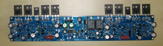
Hello ljm, its nice to see your well known amplifier in a even smaller SMD version. Can you tell us something about the difference in performance compared to the non SMD version?
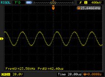
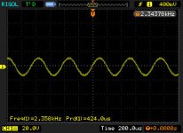
I could read in a description: Frequency Response: 20HZ-35K HZ + -3DB.
I have measured the 15D where the upper frequency was about 22K, so does it mean the output filter has changed?
Please refer to my test. Have photos and video.
2.3 K and 23 K is no attenuation frequency voltage.
About 0.5 DB less than 23 k.
http://www.tudou.com/programs/view/tdMWHx-BUOk/
video :?15????2.3?-23?_??_????????
Attachments
Last edited:
Hi Anton,
I have posted the links just because there are new versions of IRS2092 boards. The board you have posted is for sure the one that needs less effort to build a complete amplifier.
I did understand that you want to use two 600W transformers that is not necessary because one would be enough for two channels. If you want to use one transformer for each channel than 300W are enough.
For the configuration you describe I would also place the L15D close to the Transformer, use a short signal cable and longer cables for the speakers.
But I am sure many people use long signal cables for their subwoofer amplifiers without problems because only a limited bandwidth is required, so all noise above 200 Hz or below can be filtered out.
You don't in the test of time attention to too high output voltage.
Keep no more than + - 10 v test.
Because of actual use of power is very low, 20 k speakers also too won't big power.
Any music 20 k proportion of frequency information won't be too high.
So don't use a larger output voltage to frequency response test.
There may be more reliable L15D DIP parts performance.
Because DIP resistor, capacitor temperature change is small. Accuracy is higher.
Charlie, if you're pulling the trigger on this amp, please post your listening impressions. Thanks.
Hong
Trigger pulled. Amp boards arrived today. I'm waiting on some new +/-50V regulated power supplies to arrive, and then I have to find the time to mount the output devices to a heatsink, etc. I am considering testing the amp with the surplus ABLEtec power supplies that are available these days. They are slightly over voltage at +/-53V but I assume that should still be within the safety margin of the amp's design and the amp was tested at +/-54V by the designer (see page 1 of this thread).
I now have both the power supplies and the amp L50 boards.
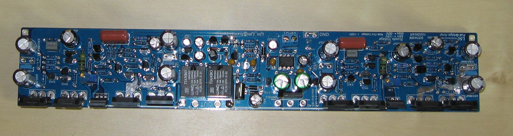
After looking over the L50 boards I found a couple of concerns:
This has nothing to do with how the board functions, it's just an assembly thing. I may need to buy a new set of output devices, remove the existing ones, and install the new ones in a more convenient orientation. I will try to take and post some pictures to demonstrate what I am talking about.
LJM, can you comment on this?
After looking over the L50 boards I found a couple of concerns:
- The board has several bare traces that carry high current. These are typically coated with solder to enhance the cross sectional area, yet none are.
- The output devices were soldered to the board on the top side. This seems backwards to me because a heatsink that spans all of the would also be very close to other metal parts like the speaker output thru-holes, the 12-0-12 AC inputs, and the wire that connects each half of the board (this seems to be installed on the "wrong" side as well).
- The board is shipped with the output devices perpendicular to the plane of the board, however, they don't clear the board edge - some kind of "adapter" seems to be necessary, perhaps an "L" of aluminum, in order to use them this way. I carefully bent all the devices and their leads 90 degrees into what seemed like a better orientation. This could crack or break leads.
This has nothing to do with how the board functions, it's just an assembly thing. I may need to buy a new set of output devices, remove the existing ones, and install the new ones in a more convenient orientation. I will try to take and post some pictures to demonstrate what I am talking about.
LJM, can you comment on this?
Attached are a couple of pictures. First, this is the board with the output devices oriented as I received it:
In the above pic, if the heatsink was attached to the output devices the edge of it would be above the board and would interfere with the holes for the speaker output (at center, bottom of pic below relays) and the AC 12-0-12 input (right of center at bottom). It could possibly touch the solder points of the wires that bring the outputs from each side of the board to the output relays. Any of these could cause a short down the road if the heat sink slides down and touches the board.
Below is the board with the changed orientation for the output devices. The problem is that the leads are still going into the board through the top side. It seems to be that it would be much better if the devices were below the board and the leads came UP through the holes. Then you could mount the board via some short standoffs, and the devices, on a large heatsink. A large heatsink is what this amp board needs afterall.
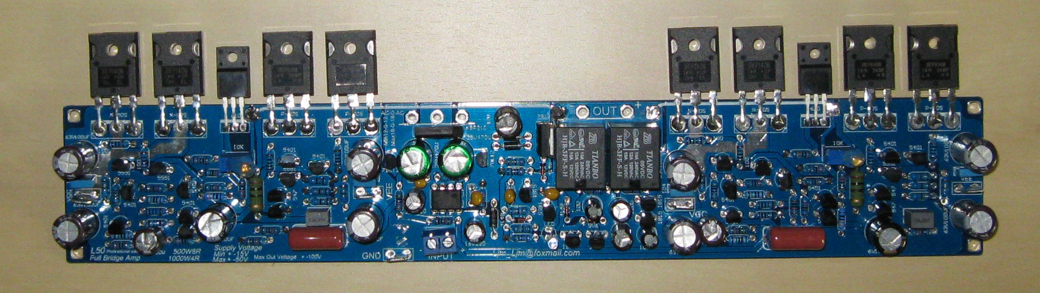
If the board could be mounted by 5-7mm standoffs to a heatsink this would keep them separated enough to prevent any shorts from occurring.
I would very much like to hear thoughts from amp builders/designers about these issues.
.
In the above pic, if the heatsink was attached to the output devices the edge of it would be above the board and would interfere with the holes for the speaker output (at center, bottom of pic below relays) and the AC 12-0-12 input (right of center at bottom). It could possibly touch the solder points of the wires that bring the outputs from each side of the board to the output relays. Any of these could cause a short down the road if the heat sink slides down and touches the board.
Below is the board with the changed orientation for the output devices. The problem is that the leads are still going into the board through the top side. It seems to be that it would be much better if the devices were below the board and the leads came UP through the holes. Then you could mount the board via some short standoffs, and the devices, on a large heatsink. A large heatsink is what this amp board needs afterall.
If the board could be mounted by 5-7mm standoffs to a heatsink this would keep them separated enough to prevent any shorts from occurring.
I would very much like to hear thoughts from amp builders/designers about these issues.
.
Attachments

Attached are a couple of pictures. First, this is the board with the output devices oriented as I received it:
In the above pic, if the heatsink was attached to the output devices the edge of it would be above the board and would interfere with the holes for the speaker output (at center, bottom of pic below relays) and the AC 12-0-12 input (right of center at bottom). It could possibly touch the solder points of the wires that bring the outputs from each side of the board to the output relays. Any of these could cause a short down the road if the heat sink slides down and touches the board.
Below is the board with the changed orientation for the output devices. The problem is that the leads are still going into the board through the top side. It seems to be that it would be much better if the devices were below the board and the leads came UP through the holes. Then you could mount the board via some short standoffs, and the devices, on a large heatsink. A large heatsink is what this amp board needs afterall.
If the board could be mounted by 5-7mm standoffs to a heatsink this would keep them separated enough to prevent any shorts from occurring.
I would very much like to hear thoughts from amp builders/designers about these issues.
.
http://www.diyaudio.com/forums/atta...0-1000w-8-ohm-l50-full-bridge-amp-l50a-10.jpg
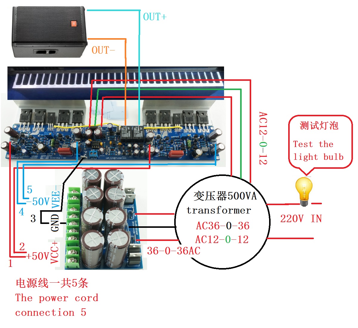
Update a few pictures about the appearance of connection diagram.
Here is the installation drawing.
First look at the picture carefully, think before you install.
Attached are a couple of pictures. First, this is the board with the output devices oriented as I received it:
In the above pic, if the heatsink was attached to the output devices the edge of it would be above the board and would interfere with the holes for the speaker output (at center, bottom of pic below relays) and the AC 12-0-12 input (right of center at bottom). It could possibly touch the solder points of the wires that bring the outputs from each side of the board to the output relays. Any of these could cause a short down the road if the heat sink slides down and touches the board.
Below is the board with the changed orientation for the output devices. The problem is that the leads are still going into the board through the top side. It seems to be that it would be much better if the devices were below the board and the leads came UP through the holes. Then you could mount the board via some short standoffs, and the devices, on a large heatsink. A large heatsink is what this amp board needs afterall.
If the board could be mounted by 5-7mm standoffs to a heatsink this would keep them separated enough to prevent any shorts from occurring.
I would very much like to hear thoughts from amp builders/designers about these issues.
.
Transistors. The feet, L is required.
Do not stand directly. Very easy.
Attachments
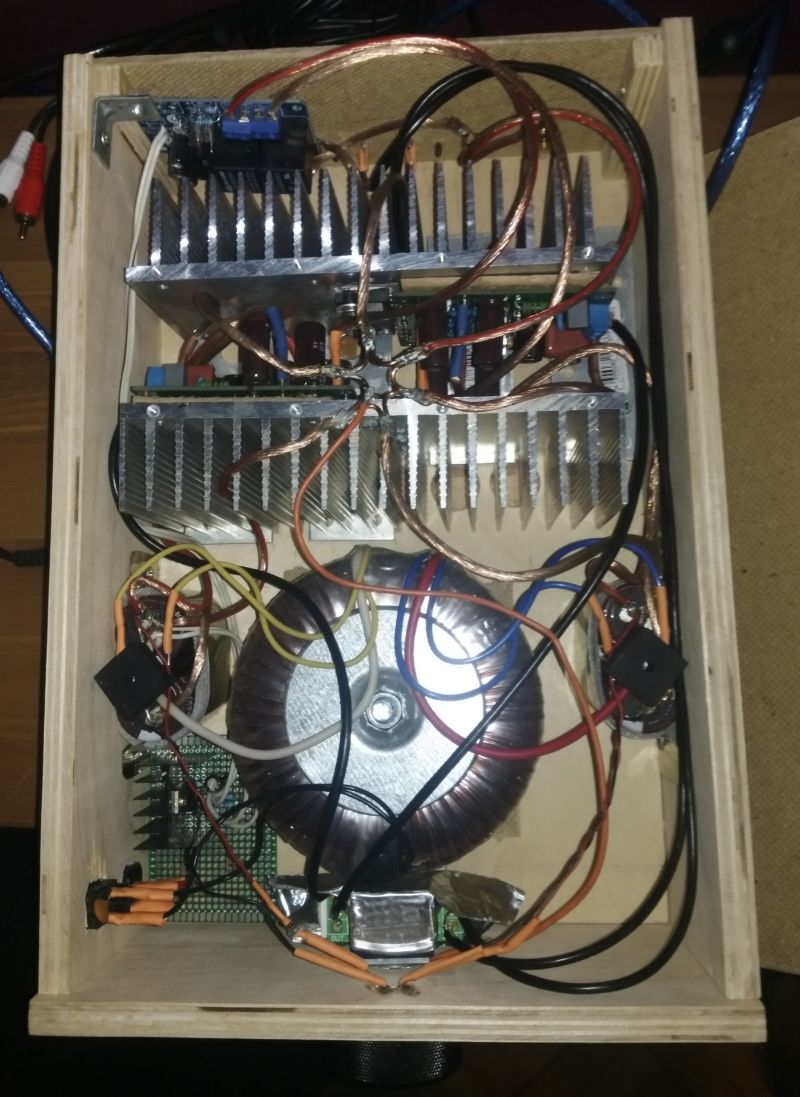
My L7 amp
Hi
I have finished my amp based on this kit.
The parts I used:
- kit containing 2 pcbs and all parts soldered by myself
- 2 of large aluminium heatsinks
- 200W transformer 220/4*25V
- 4 of capacitors 10000u*50V
- 2 of rectifiers KBPC1010
- speaker protection board kit soldered by myself
- ALPS 27 potentiometer (not fake I hope)
- large 44mm knob
- input and speaker terminals
- some speaker wire
- some microphone wire
- power socket and switch
- 2 little leds with resistors
- plywood cabinet, handmade
Finally, it was worth it. The sound is so clear and so nice that I decided to send to retire my Sony reciever that served to me for 10 years. Goodbye, Sony )
PS: while writing it, I realized my error: I shoud use 2*50AC power. Although, then I should buy other filter capasitors for 80V or 100V (50V ones was on hand). Yet, I like the result. Maybe, one time I make another amp, using right transformer, right cabinet, and add some new features. Likely, it will be another L7.
Attachments

33uf oscons
hi ljm,
i ordered the l15d kit. it sounds terrific. it came from zoe-tzang with 33uf oscons and 270ohm resistor in place of the 470r. i thought it might be a mistake, so i put in 22uf and changed resistor to 470r. so i just now see that you recommend 33uf. if i try 33uf oscons, should i change back to 270r? thank you. these amps are amazing.
regards,
freeman
Last edited:
Hope any of you can help me, I am desperate :-(
I have a pair of L15D pro boards bought on ebay I planned to use them for my bass in a bridged setup.
I checked them at arrival, both were OK, but I had no time to put them in the enclosure and actually start to use them for long months. What I did was to put the phase inverter circuit on one of the board (thanks Rens!). Last week I decided to give them a try on my bass cab, so I wired them up to the old PS I was using (+-50V).
Only one of the boards started to work, the one I put the small PCB on did not want to fire up. I've identified a dead 5V6 zener (that feeds the 2092) so I replaced it. Still no luck.
Then I accidentally killed it by mixing up DC IN cables (ground and VCC+).
Living in Hungary it is not easy to buy any spare parts, so I was hoping you can provide me with some advice how to proceed.
What I've identified as dead so far are the 5551s in the protection part, maybe the IRFB4019s are also dead (not sure how to check it) and probably the IRS2092 too (any way to check?).
So, please let me know how can I check whether the FETs and the IRS chip is dead?
I can buy them from Aliexpress if needed, but what about the NCC5551s?
Thanks in advance
What is the maximum supply voltage for the L-15D-Pro board with two IRFB4019 power transistors . Is it +/- 50 V ( trafo 40-0-40). Does this also mean that we need to increase the heatsink size if used with a 4 ohms load ( 300W) ?
That is what the web site appears to say.
Thanks.
That is what the web site appears to say.
Thanks.
Hi ljm_ljm,
sorry, I made a mistake when I checked the frequency response. I have repeated the measurement a few days later with a 5R dummyload and white noise and sine wave sweeps and there was no limitation in the response from 20 Hz till 30 KHz.
Thanks for your feedback!
Hi Buehgemeiste,
I hope this is what you are looking for:
Aliexpress.com : L15DSMD IRS2092S Klasse D Super Power 250 Watt Einkanal Digitale Fertig Verstrkerplatine von verlsslichen verstrker hf-Lieferanten auf TZT Trading kaufen
Some update just for fun.Hope any of you can help me, I am desperate :-(
I have a pair of L15D pro boards bought on ebay I planned to use them for my bass in a bridged setup.
I checked them at arrival, both were OK, but I had no time to put them in the enclosure and actually start to use them for long months. What I did was to put the phase inverter circuit on one of the board (thanks Rens!). Last week I decided to give them a try on my bass cab, so I wired them up to the old PS I was using (+-50V).
Only one of the boards started to work, the one I put the small PCB on did not want to fire up. I've identified a dead 5V6 zener (that feeds the 2092) so I replaced it. Still no luck.
Then I accidentally killed it by mixing up DC IN cables (ground and VCC+).
Living in Hungary it is not easy to buy any spare parts, so I was hoping you can provide me with some advice how to proceed.
What I've identified as dead so far are the 5551s in the protection part, maybe the IRFB4019s are also dead (not sure how to check it) and probably the IRS2092 too (any way to check?).
So, please let me know how can I check whether the FETs and the IRS chip is dead?
I can buy them from Aliexpress if needed, but what about the NCC5551s?
Thanks in advance
Luckily I found a local (online) store which sells the IRFBs and the IRFI chip too. For the protection part I used MPSA42 transistors (pins had to be twisted). Put them together ( replacing the chip was a bit tricky) and now the board is back in business

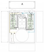
L15D Pro chassis and layout
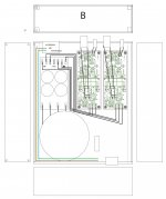
Hello,
I've been using a L15D Pro for a while now on a breadboard. I finally decided to build it a proper chassis as I love the sound it makes.
I did some drawings to figure out how to route the signal and 220V cables and arrange the amp boards and the PSU elements.
I read somewhere that the amp boards should not be too close together. If that is a myth, then I guess, version B would be preferred .
Thank's
Version A
Signal and 220V cables cross each other but amp boards are further apart
Version B
Signal and 220V cables don't cross each other but amp boards are very close.
The chassis is about w250mm x d300mm x h70mm
Attachments
Last edited:
Just as additional information, there is also a version 2 of the L15D with other capacitors:
Assembled L15D LMJ 2.0 Channel Class D Audio Power Amplifier IRS2092+IRF14019H
Hi, which speaker protection board would you recommend for this amplifier ? And does it need its own power supply (or can I use the transformer ?)
Do you have an ebay link ?
Greetings.
Last edited:
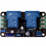
Hi r100,
there are many options for speaker protection. I have used this ready build board for my amplifier:
module protection pour haut parleur
It is a DC protection with 30A relais and a potentiometer to adjust the switch on time.
there are many options for speaker protection. I have used this ready build board for my amplifier:
module protection pour haut parleur
It is a DC protection with 30A relais and a potentiometer to adjust the switch on time.
Attachments
Hi r100,
I forgot to answer regarding the power supply. Yes, most of the protection boards need a separate (12V) AC supply. It can be a separate winding of a transformer. If you would use the DC voltage after a capacitor bank the stored energy of the capacitors will take a while to unload so the relais will switch off to late and you might hear some noise from the speakers when you switch off the amplifier.
I forgot to answer regarding the power supply. Yes, most of the protection boards need a separate (12V) AC supply. It can be a separate winding of a transformer. If you would use the DC voltage after a capacitor bank the stored energy of the capacitors will take a while to unload so the relais will switch off to late and you might hear some noise from the speakers when you switch off the amplifier.
- Home
- Vendor's Bazaar
- LJM Audio