Yes, it is quite possible to compensate the total impedance to nearly resistive so that the frequency responses become fairly equal in both modes, but as I see it, the sound with voltage amplifiers will actually only improve in proportion to the increase in the impedance seen by the drivers...
I have lately worked on a speaker concept that can be used with ordinary voltage amplifiers and where sensitivity and efficiency are willingly traded for current and sound purity..... by using 4-ohm drivers instead of 8. The idea has now been registered as a Utility Model in Finland but is free to be utilized elsewhere.
Excellent, I think this is the way to go and very VERY important... but this shifts the focus on the speaker and there are techniques that can be explored to maximise the current drive effect with Voltage delivery - and NOW we are talking DIY possibilities.
Yes, I did take a look at that drawing, but naturally re the text I don't understand Suomi.
I have nicked "Kuva 4" and posted here - if you have any objection I will withdraw it immediately at your say-so.
I have a some comments to make. For others to follow along it needs to be visible.
1. Yes, the use of 4 Ohm drivers makes sense. But I was interested in you nominating "five times" as that is pretty much what I stated to the Audiophile Society of NSW here in Sydney, Australia, middle of last year. As a rule of thumb using the definition of a Voltage interface, maximum 1dB insertion loss, means near 1/10th the output impedance or less. So following the same convention inversely, this should be 10x or higher to qualify for Current version. But substantial benefits at 5x for sure. I note that Nelson Pass F1J is 50 Ohms and he has experimented with FR speakers that are mostly 8 Ohm.
2. Your "Kuva 4" approach should suit large vertical arrays, line sources, where large gains in sensitivity can more easily be gained.
3. The Tweeter would benefit from being very high sensitivity, even some kind of WG or other horn loading. This would maximise the "4" Resistor value as high as possible and make "7" capacitor a much smaller value - and get a large series reactance, especially in the critical lower treble and upper midrange (the ears max sensitivity is not 1Khz and this must be an important factor).
4. The speaker that comes out of such a process could well be compatible with both Voltage and Current amps. The overall Z needs to be flat, with LCR treatment of the LF resonance as you show. But what is your attitude towards the use of conduits which are before the crossover and across the amplifier's terminals? Then the current, whether from a current source or voltage source, will be linear and the overall Z will be flat. It will then be compatible with all types of amplifiers.
Here is a real world measured example from a ported design, the LCR is tuned to the upper peak but due to its Q the lower peak also are suppressed about 30-40% and uses conduit filters to equalise current:
5. Ironically, the virtual ideal amplifier could be described as a Voltage amplifier with infinite output impedance and infinite voltage swing. For DIY use, it would be realistic to make amplifiers that can swing lots of Volts and less (but still sufficent) current. DIY could get its teeth into this, Current driving benefits (up to a reasonable degree) becomes achievable - and DIY may lead the commercial world in a newer and more positive direction. It may be a compromise, but still a good compromise.
6. If you do speaker design modelling something very interesting becomes apparent with series resistance on the amplier's output terminals and before the crossover, the effect on the electrical phase angle. Flat impedance equals flat electrical phase angle and so does higher series resistance. I want to dwell a bit on that:
This raises some questions in my mind and I would appreciate any thoughts you have. If we pare down a Current amplifier as an amplifier that can only (ideally) deliver linear Current (due to high output Z), then the current on the amplifier will always be linear on its output, it will always have zero degree electrical phase angle. Current amplifiers can only deliver linear current because that is the effect of the (ideally speaking) infinite series output resistance. Here is an example where a commercial speaker is driven from different source impedances, see what happens to the electrical phase angle:
What effect this has on the speaker's frequency response and more is of course something else. But the current goes linear no matter what the speaker's load (of course, a bad crossover can still mess things up).
Question: What if we make a speaker load that only demands linear current? The point of the interface of the speaker system and that of the amplifier, whether current source or voltage source or anything in between, the current at that point will always be linear.
Let me just say, we have done some work in this area and we are talking about audible improvement, no matter what the theory might say (and you may enlighten further on that), but something good must be working in our favour even if not fully understood. The usual maximising of the circuit is still needed, but an additional conduit filter(s) to mirror current - of which your bass LCR is of that type, is desirable because the results are an audible improvement. The use of simple 1st order filters is obligatory as I know we both agree.
In conclusion, rather than thinking strictly in purest terms about Current delivery, we need to adapt to a more flexible way of thinking and maximising the effect to suit Voltage delivery as well. I for one is convinced that 2-4KHz is where the focus should be and is often also associated with the Tweeter, at near the bottom of its bandwidth or bandpass, being a source of some of the worst distortion in dynamic speakers. And with some enginuity we can find clever ways to get close to 5x at least here. It's been done and I am here to tell you it works.
This approach shifts the focus from the amplfier design and towards speaker design.
Just another way to view certain aspects of the above. Think of a Voltage amplifier, then a series resistance, then the speaker system. If the series resistance is HIGH, then it does not matter whether it belongs to the Voltage amp OR the speaker. It is STILL current delivery.
Also, a 30-80% of something is better than 100% of nothing.
Cheers, Joe R.
Last edited:
Joe, if that schematic comes from a patent application, it's in the public domain and you can certainly use it (the drawing, not the patented circuit!).
That may well be so, still I think it proper to ask the question.
I believe, to paraphrase if not the exact words, he also said we could use the idea for personal use.
Cheers, Joe
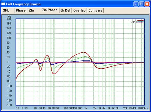
I think this would also be of interest. The graphic/plot below shows the electrical phase of the sample system posted above.
To avoid confusion I will post both together:
This was the system Z as per above:
This is the electrical phase angle that results:
Any series resistance will flatten it even further.
Now for the affect it will have on the frequency response. Below the Red plot is Zero Ohm Voltage delivery. Since this is a flat 6 Ohm design, then the 5x Green plot is 30 Ohm series resistance and hence defines the amplifier's output impedance - the Green 5x plot is +10dB to keep them visually close to each other.
Speaks for itself.
That 30 Ohm (5x) series resistance linearises the current futher - keep an eye on the Green plot:
But you will agree the the Red plot representing Voltage drive is still very flat.
Cheers, Joe R.
Last edited:
That's how I also think. The threshold for experimenting is pretty much lowered if one can do with ordinary and familiar amplification gear. Commercial possibilities should also be enhanced.Joe Rasmussen said:I think this is the way to go and very VERY important... - and NOW we are talking DIY possibilities.
In terminology however, it is questionable whether it can be called current drive when the amplifier is delivering voltage. Therefore, I am naming the concept as 'clean-current speaker'.
To get the best results, I also recommend, in general:
- to avoid, where possible, using drivers in their break-up region, as the ill effects from these may counteract the improvement obtained from minimizing the inductance effects.
- to use more effective than usual stuffing to suppress the level of cabinet noise that passes the cone(s).
- using a tweeter with low resonant frequency and preferably without ferrofluid. (Wavecor TW030WA05 is one such rarity.)
Waveguides are quite usable if the diaphragm can bear the loading, but high-sensitivity motors do not necessarily help since the relative proportion of EMF:s in the driver also increases with sensitivity, increasing consequently the needed series impedance. I believe that a smallish two-woofer system can still be mated with an ordinary tweeter when the baffle step compensation is regarded.Joe Rasmussen said:The Tweeter would benefit from being very high sensitivity, even some kind of WG or other horn loading. This would maximise the "4" Resistor value as high as possible and make "7" capacitor a much smaller value - and get a large series reactance, especially in the critical lower treble and upper midrange
As current source amplifiers are not available, I don't think there is yet need for such compatibility. Also, if something extraneous is connected across the amplifier's terminals, it will no longer work as a proper current source. The same with voltage amplifiers and series networks.Joe Rasmussen said:But what is your attitude towards the use of conduits which are before the crossover and across the amplifier's terminals? Then the current, whether from a current source or voltage source, will be linear and the overall Z will be flat. It will then be compatible with all types of amplifiers.
I cannot see any direct reason for the improvement you are experiencing if the conduit filters before the speaker system are not somehow affecting the frequency response. Mere parallel networks at voltage amp's terminals and mere series networks at current amp's terminals should not, in principle, alter the speaker's signal. Maybe the amplifier finds it easier to drive a resistive rather than a highly reactive load.Joe Rasmussen said:Question: What if we make a speaker load that only demands linear current? The point of the interface of the speaker system and that of the amplifier, whether current source or voltage source or anything in between, the current at that point will always be linear.
Let me just say, we have done some work in this area and we are talking about audible improvement, no matter what the theory might say (and you may enlighten further on that), but something good must be working in our favour even if not fully understood. The usual maximising of the circuit is still needed, but an additional conduit filter(s) to mirror current - of which your bass LCR is of that type, is desirable because the results are an audible improvement. The use of simple 1st order filters is obligatory as I know we both agree.
(Your use of the word 'linear' may cause some confusion when you actually seem to mean that the current is in phase with the applied signal. Linearity, in the context of linear systems, usually indicates that the system does not generate extraneous frequencies, i.e. harmonic or modulation distortion.)
Utility models (possible in some countries), like patents, only have effect in those countries where they are in force. So there is no restriction even for commercial use, except in Finland; and I welcome all proper designs and products that can enhance the cause of current drive.Joe Rasmussen said:I believe, to paraphrase if not the exact words, he also said we could use the idea for personal use.
My patent applications in GB now seem to have been published. One is about the frequency balancing of cone drivers and the other about transistor-based power protection means:
Compensation of Rising Frequency Response in Passive Current-Driven Loudspeakers
Protection Circuit for Current-Driven Loudspeakers
Any thoughts or comments?
Compensation of Rising Frequency Response in Passive Current-Driven Loudspeakers
Protection Circuit for Current-Driven Loudspeakers
Any thoughts or comments?
Current amplifiers made of voltage regulators
It seems that adjustable voltage regulators are quite well suited for implementing current amps. Positive regulators can be easily used to make controlled current sources with acceptably low distortion. Negative regulators, however, have much poorer ripple rejection properties at high frequencies and therefore are not usable.
Below are drawn the basic configurations for such sources. Figure 'a' shows a constant-current source that can be used at both ends; node A can be at a given potential while node B acts as a current source, or then B can be at a given potential while A acts as a current sink. Current flowing from the adjustment terminal is always constant at about 50 uA and can thus be neglected. The current I, which is therefore equal at the IN and OUT terminals of the reg, is always the regulator reference voltage (1.25V) divided by R.
Figure b shows the operation as a voltage-controlled current sink. The input voltage is reflected as such in the voltage across R which determines the current through the reg. To keep losses moderate, negative input signals need to go below the supply rail, but this is not a problem.
Figure c shows a floating current-controlled current source. The input current flowing through the gain setting resistor Rg develops a voltage drop that increases or decreases the voltage across R and hence controls the current flowing to the load.
It doesn't come without NFB since it is inherent in the regulators, but the load seen by the feedback systems is always resistive.
By combining blocks b and c we can build class A current source amplifiers without the usual way of adding a current feedback around a voltage delivering amplifier. There is also the benefit that in a bridged connection the other side can be and ordinary class AB voltage amplifier without any sacrifice to performance.
It seems that adjustable voltage regulators are quite well suited for implementing current amps. Positive regulators can be easily used to make controlled current sources with acceptably low distortion. Negative regulators, however, have much poorer ripple rejection properties at high frequencies and therefore are not usable.
Below are drawn the basic configurations for such sources. Figure 'a' shows a constant-current source that can be used at both ends; node A can be at a given potential while node B acts as a current source, or then B can be at a given potential while A acts as a current sink. Current flowing from the adjustment terminal is always constant at about 50 uA and can thus be neglected. The current I, which is therefore equal at the IN and OUT terminals of the reg, is always the regulator reference voltage (1.25V) divided by R.
An externally hosted image should be here but it was not working when we last tested it.
Figure b shows the operation as a voltage-controlled current sink. The input voltage is reflected as such in the voltage across R which determines the current through the reg. To keep losses moderate, negative input signals need to go below the supply rail, but this is not a problem.
Figure c shows a floating current-controlled current source. The input current flowing through the gain setting resistor Rg develops a voltage drop that increases or decreases the voltage across R and hence controls the current flowing to the load.
It doesn't come without NFB since it is inherent in the regulators, but the load seen by the feedback systems is always resistive.
By combining blocks b and c we can build class A current source amplifiers without the usual way of adding a current feedback around a voltage delivering amplifier. There is also the benefit that in a bridged connection the other side can be and ordinary class AB voltage amplifier without any sacrifice to performance.
As I recall from the datasheets, the MC78xx has better stats than the rest (LM78xx, TL78xx...) for some reason. Just FYI. Also some negative regulators DO have better specs than the positive versions.
Cascoding with another regulator would probably improve performance, just like when they are used normally.
- keantoken
Cascoding with another regulator would probably improve performance, just like when they are used normally.
- keantoken
You are quite right with the cascoding as thereby the ripple rejection properties of the regulator can be made immaterial. The price is, however, that there are two dropout voltages instead of one. What I have observed from the LM317, 350 and 338 is also that their ripple rejection is at such a good level that the output impedance becomes a more significant source of nonideality.keantoken said:As I recall from the datasheets, the MC78xx has better stats than the rest (LM78xx, TL78xx...) for some reason. Just FYI. Also some negative regulators DO have better specs than the positive versions.
Cascoding with another regulator would probably improve performance, just like when they are used normally.
For the types mentioned, I haven't found much alternatives though their dropouts are relatively high. These are also stable without any output capacitors. (I think the 78xx series are all for fixed voltages.)
25W class A transconductance amplifier
Here is a completed and tested schematic of a class A regulator-based current-mode amplifier, that can deliver a good 25 W into 8 ohms. The operation is bridged, due to which the idling power consumption is very moderate at 54 watts and the amp runs on a single 30 V supply. The transconductor stage consists of two pairs of LM317:s with a quiescent current set to 1.7 A. The LM1875 only generates the background potential for the load but is not critical to sound quality since the load current is determined solely by the transconductor side.
The principle is quite ideal for those who for prefer class A operation or carry doubts about global NFB. Though the regulators each are feedbacked devices, the load seen by them always remains resistive.
The development work has taken some time, but the result is well worth it. Stripboard layout is available.
Performance figures:
Output power: >25W @8ohm; >15W @16ohm
THD @1kHz: 0.05% @25W; 0.045% @1W
SNR @25W (up to 20kHz, unweighted): 90dB
Idling power: 54W
Efficiency @25W: 32%
Sensitivity: 0.70V
Input impedance: 18kohm
The MC34072 with the NPN transistor act as a voltage buffer to drive the lower regulators and, at the same time, as a voltage/current converter to drive the upper regulators. The upper ones are connected as current-controlled current sources while the lower ones work as voltage-controlled current sinks, as depicted in post #287.
R5, R6 and P1 are to supply the bias current for the NPN. Trimmer P1 is used to null DC current through the load.
The LM1875 operates in an inverter configuration taking care that the two load ends move symmetrically around the middle potential. The gain is not exactly -1 but -1.15 to utilize the available voltage headrooms maximally.
One practical benefit of current-drive is also that it is possible to build class A amplifiers with only a fraction of the power losses inevitable with voltage design. Here the regulators and the background amplifier use the same supply rails, but by lowering the voltage across the power-hungry transconductor stage (even down to some +/-6 V) and correspondingly increasing it for the class B or AB background amp, it is possible to get well over 50% in efficiency.
Here is a completed and tested schematic of a class A regulator-based current-mode amplifier, that can deliver a good 25 W into 8 ohms. The operation is bridged, due to which the idling power consumption is very moderate at 54 watts and the amp runs on a single 30 V supply. The transconductor stage consists of two pairs of LM317:s with a quiescent current set to 1.7 A. The LM1875 only generates the background potential for the load but is not critical to sound quality since the load current is determined solely by the transconductor side.
An externally hosted image should be here but it was not working when we last tested it.
The principle is quite ideal for those who for prefer class A operation or carry doubts about global NFB. Though the regulators each are feedbacked devices, the load seen by them always remains resistive.
The development work has taken some time, but the result is well worth it. Stripboard layout is available.
Performance figures:
Output power: >25W @8ohm; >15W @16ohm
THD @1kHz: 0.05% @25W; 0.045% @1W
SNR @25W (up to 20kHz, unweighted): 90dB
Idling power: 54W
Efficiency @25W: 32%
Sensitivity: 0.70V
Input impedance: 18kohm
The MC34072 with the NPN transistor act as a voltage buffer to drive the lower regulators and, at the same time, as a voltage/current converter to drive the upper regulators. The upper ones are connected as current-controlled current sources while the lower ones work as voltage-controlled current sinks, as depicted in post #287.
R5, R6 and P1 are to supply the bias current for the NPN. Trimmer P1 is used to null DC current through the load.
The LM1875 operates in an inverter configuration taking care that the two load ends move symmetrically around the middle potential. The gain is not exactly -1 but -1.15 to utilize the available voltage headrooms maximally.
One practical benefit of current-drive is also that it is possible to build class A amplifiers with only a fraction of the power losses inevitable with voltage design. Here the regulators and the background amplifier use the same supply rails, but by lowering the voltage across the power-hungry transconductor stage (even down to some +/-6 V) and correspondingly increasing it for the class B or AB background amp, it is possible to get well over 50% in efficiency.
The measured output impedance of the above transconductor is seen here. Up to about 4 kHz, it ranges from 1k to 10k, reaching a minimum 200 ohms at 20 kHz. Above 400 Hz, Zout is quite inversely proportional to frequency (capacitive) and is mostly due to C6. At low frequencies, the value becomes limited by the regulators' line regulation properties.
The frequency behavior of the adjustable regulators is also very satisfactory for amplification purposes. With the circuit shown, the response is less than 0.3 dB down at 20 kHz. The low limit is determined by C1 and also C5.
As for stability issues, the circuit hasn't shown any signs of instability with any loads from zero ohms to highly inductive loads and voice coils and with varying input and supply levels.
A nice and economic feature with using this type of transconductor is yet that the amp can be used in a low power mode when only low or moderate listening levels are needed. By switching resistors R11 and R13 out, the regulator bias current and hence power consumption becomes halved while the circuit still operates normally but only with halved current capability and sensitivity. This also halves the background hiss though it is hardly discernible at normal distance even in the full mode.
An externally hosted image should be here but it was not working when we last tested it.
The frequency behavior of the adjustable regulators is also very satisfactory for amplification purposes. With the circuit shown, the response is less than 0.3 dB down at 20 kHz. The low limit is determined by C1 and also C5.
As for stability issues, the circuit hasn't shown any signs of instability with any loads from zero ohms to highly inductive loads and voice coils and with varying input and supply levels.
A nice and economic feature with using this type of transconductor is yet that the amp can be used in a low power mode when only low or moderate listening levels are needed. By switching resistors R11 and R13 out, the regulator bias current and hence power consumption becomes halved while the circuit still operates normally but only with halved current capability and sensitivity. This also halves the background hiss though it is hardly discernible at normal distance even in the full mode.
Thanks for the info. I think square-law class A is a good candidate for current-mode amplifiers:
Linear Audio | your tech audio resource
Linear Audio | your tech audio resource
I'd say that Depletion MOSFETs are much better at that...It seems that adjustable voltage regulators are quite well suited for implementing current amps.
BTW: an interesting project of a very different kind of current mode amplifier: "www.audiofaidate.org - Argento Vivo".
(sorry, Italian language. Try with Google Translate). You need to (freely) register to the forum in order to view attached images/files.
(sorry, Italian language. Try with Google Translate). You need to (freely) register to the forum in order to view attached images/files.
Some amendment to the amplifier above:
Like conventional amps, current-output ones also usually need some muting of the on/off switching transients, and the topology presented is no exception. However, in current mode this can be done by shorting the speaker leads instead of breaking. Also, bulky and themselves noise making relays are not necessary, for the task can be accomplished with power mosfets.
Below is a muting circuit suitable for this. When the BJT is in off state, the mosfet gates are at the supply potential, keeping the fets conductive with low on-resistance. When the BJT is conducting enough, the gates (and sources alike) get very low potential which turns off the fets thus releasing the speaker terminals. R1 with C provides a delay that keeps the muting on during the power-up situation. When the supply is falling, C is discharged through the diode and the BJT turned off (and the fets on) without delay.
The control circuit driving the gates can be common for all channels. When using other supply voltages than 30V, only R2 needs to be adjusted to keep the threshold level suitable at about 80% of the full voltage.
_______
In the amplifier schematic, capacitor C9 can actually be left out, for it is not really necessary to reference the non-inverting input to ground here. This even improves the overall PSRR somewhat.
Like conventional amps, current-output ones also usually need some muting of the on/off switching transients, and the topology presented is no exception. However, in current mode this can be done by shorting the speaker leads instead of breaking. Also, bulky and themselves noise making relays are not necessary, for the task can be accomplished with power mosfets.
Below is a muting circuit suitable for this. When the BJT is in off state, the mosfet gates are at the supply potential, keeping the fets conductive with low on-resistance. When the BJT is conducting enough, the gates (and sources alike) get very low potential which turns off the fets thus releasing the speaker terminals. R1 with C provides a delay that keeps the muting on during the power-up situation. When the supply is falling, C is discharged through the diode and the BJT turned off (and the fets on) without delay.
An externally hosted image should be here but it was not working when we last tested it.
The control circuit driving the gates can be common for all channels. When using other supply voltages than 30V, only R2 needs to be adjusted to keep the threshold level suitable at about 80% of the full voltage.
_______
In the amplifier schematic, capacitor C9 can actually be left out, for it is not really necessary to reference the non-inverting input to ground here. This even improves the overall PSRR somewhat.
I only haven't found practical examples on this.UnixMan said:I'd say that Depletion MOSFETs are much better at that...
Most people use opto-isolators for MOSFET relays. Omron has some good solid state relays.
Your circuit doesn't appear to work. If the gates of the MFETs are driven, the parasitic capacitance will leak current into the sources and keep the gates and sources at the same potential. Where is the gate drive current loop? Furthermore, as the output voltage approaches the rails, the Vgs will be modulated, changing the relay resistance (but this may not matter if only used to short).
Your circuit doesn't appear to work. If the gates of the MFETs are driven, the parasitic capacitance will leak current into the sources and keep the gates and sources at the same potential. Where is the gate drive current loop? Furthermore, as the output voltage approaches the rails, the Vgs will be modulated, changing the relay resistance (but this may not matter if only used to short).
Hello keantoken
These issues do not pose problems, and the operation has been verified. In this use, there is no need to pay for opto-isolation. Wide availability of the parts is also a consideration.
When the gates are driven up, The parasitic Cgs capacitances do inject some microamperes to the source point, but due to the internal bulk diodes of the mosfets (not drawn) the source potential cannot rise much higher than the lower of the two drain (speaker) potentials. When the gates are driven down, the gate protection zener becomes forward-biased pulling the source point close to ground potential.
In the switch-off state, the parasitic capacitance loading the drains is less than a nanofarad, which can also be neglected. (The drain potentials must, of course, remain higher than the control circuit ground.)
- Status
- This old topic is closed. If you want to reopen this topic, contact a moderator using the "Report Post" button.
- Home
- Vendor's Bazaar
- The Secret of Tube Amplifiers Revealed - and much more!