Stuffing and Adjustment Procedures:
1. Solder resistors, LED and diodes
2. Solder film capacitors except the BIG 10uF cap
3. Solder all jumper pins
4. Solder IC sockets
5. Solder bead, inductors
6. Solder Pulse transformer
7. Solder all pots (VR)
8. Solder small E-caps (22uF to 330uF)
9. Solder Regulator Jfet / Transistors / TL431 etc.. (do not solder jfet IV fets)
10. Solder connectors if used
11. Solder big E-caps (1000uF and 2200uF)
12. Solder all relays
13. Solder IRF610/9610 with heat sink
14. Verify the +/- 20V regulator (across R59 and R60) is working and adjust the output voltage.
15. If cannot adjust the voltage to 20V, solder a 220k resistor and parallel to R47, R48, R65 or R66. Do this when needed.
16. Then solder the Jfet IV FETs section module by module.
17. Power up again and adjust Pot R1 until Point A to 10Vdc, Adjust Pot R2 until Point B is 0Vdc, Repeat adjustment on R1 and R2 when necessary.
18. Then adjust Pot R8 until voltage across R14 is 5Vdc.
19. Repeat to solder other Jfet IV section and adjust voltages as above.
20. Solder the LM317 and 337 with heat sink in pairs and verify the regulator output voltage is 5V +/-0.1V at the PCM63 IC socket positions.
21. Repeat and verify all regulators to PCM63 is either +5 or -5V.
22. Verify the +20/-20V regulators are still at correct voltage. This voltage should not change more than 0.2V or else something may be wrong.
23. Now solder the 7805 and 7808 in the digital sections and verify all output voltage correct. You can check voltage at the IC sockets pins to double confirm.
24. Solder the 8412/8414 chips in position. Plug in 5842 chip.
25. Short the pins for 8414 power to clock regulator. Also select the input jumper to RCA socket (right side two pins shorted).
26. Power up the digital section, the error LED should be ON after 1 second. Then inject a SPDIF signal to the RCA digital in socket, the Error LED should be OFF now.
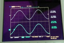
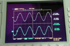
27. Use a scope to check if there is pulsed at CLK, LE, DOL and DOR nets. If don’t have scope, use a DC voltmeter and check voltage is about 2.5Vdc.
28. Power down and go back to DAC section.
29. Plug in PCM63 first chip.
30. Verify the Iout is at 0V dc (point B), if not, fine tune the R2. Note that this voltage should not change much after the first adjustment. Check point A still at about 10V.
31. Repeat for other PCM63 one by one.
32. Then check the current drain at R81 and R82 (5.1 ohm resistors). The voltage drop across R81 is about 0.97V while the voltage at R82 is about 1.15V.
33. Solder the 4 BIG film caps 10uF.
34. If everything is fine, plug in transport and you should hear music from the output.
35. Perform normal testing with a test CD.
36. Warm up the set for 1 hrs and adjust the voltage at point A and B again when needed.
Notes:
1. The “+” mark on D10 LED is wrong polarity.
END
1. Solder resistors, LED and diodes
2. Solder film capacitors except the BIG 10uF cap
3. Solder all jumper pins
4. Solder IC sockets
5. Solder bead, inductors
6. Solder Pulse transformer
7. Solder all pots (VR)
8. Solder small E-caps (22uF to 330uF)
9. Solder Regulator Jfet / Transistors / TL431 etc.. (do not solder jfet IV fets)
10. Solder connectors if used
11. Solder big E-caps (1000uF and 2200uF)
12. Solder all relays
13. Solder IRF610/9610 with heat sink
14. Verify the +/- 20V regulator (across R59 and R60) is working and adjust the output voltage.
15. If cannot adjust the voltage to 20V, solder a 220k resistor and parallel to R47, R48, R65 or R66. Do this when needed.
16. Then solder the Jfet IV FETs section module by module.
17. Power up again and adjust Pot R1 until Point A to 10Vdc, Adjust Pot R2 until Point B is 0Vdc, Repeat adjustment on R1 and R2 when necessary.
18. Then adjust Pot R8 until voltage across R14 is 5Vdc.
19. Repeat to solder other Jfet IV section and adjust voltages as above.
20. Solder the LM317 and 337 with heat sink in pairs and verify the regulator output voltage is 5V +/-0.1V at the PCM63 IC socket positions.
21. Repeat and verify all regulators to PCM63 is either +5 or -5V.
22. Verify the +20/-20V regulators are still at correct voltage. This voltage should not change more than 0.2V or else something may be wrong.
23. Now solder the 7805 and 7808 in the digital sections and verify all output voltage correct. You can check voltage at the IC sockets pins to double confirm.
24. Solder the 8412/8414 chips in position. Plug in 5842 chip.
25. Short the pins for 8414 power to clock regulator. Also select the input jumper to RCA socket (right side two pins shorted).
26. Power up the digital section, the error LED should be ON after 1 second. Then inject a SPDIF signal to the RCA digital in socket, the Error LED should be OFF now.
27. Use a scope to check if there is pulsed at CLK, LE, DOL and DOR nets. If don’t have scope, use a DC voltmeter and check voltage is about 2.5Vdc.
28. Power down and go back to DAC section.
29. Plug in PCM63 first chip.
30. Verify the Iout is at 0V dc (point B), if not, fine tune the R2. Note that this voltage should not change much after the first adjustment. Check point A still at about 10V.
31. Repeat for other PCM63 one by one.
32. Then check the current drain at R81 and R82 (5.1 ohm resistors). The voltage drop across R81 is about 0.97V while the voltage at R82 is about 1.15V.
33. Solder the 4 BIG film caps 10uF.
34. If everything is fine, plug in transport and you should hear music from the output.
35. Perform normal testing with a test CD.
36. Warm up the set for 1 hrs and adjust the voltage at point A and B again when needed.
Notes:
1. The “+” mark on D10 LED is wrong polarity.
END
For those interested, can email me. 10 pcs board are still available and the rest already booked by other members.
Price of ver2 board is US$25. Shipping with registered mail is $8. Thus total will be $33.
8414 to 8412 converter board is $1.
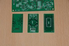
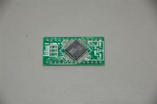
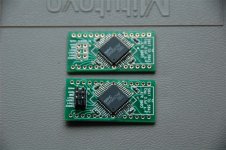
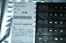
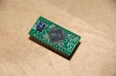
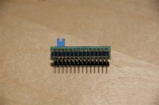
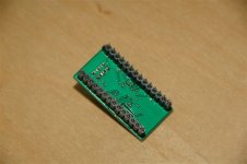
I shall release a SM5847 to SM5842 converter board soon and price of this gold plated board is $5. Pins and 4 ceramic smd capacitors will be included. I shall post photo when I receive the chip and tested working. I am able to provide 6 SM5847 IC for sales and price is $20 each.
Selected parts are avaliable but with limited quantity. See list attached.
Thanks for all your interest.
Price of ver2 board is US$25. Shipping with registered mail is $8. Thus total will be $33.
8414 to 8412 converter board is $1.
I shall release a SM5847 to SM5842 converter board soon and price of this gold plated board is $5. Pins and 4 ceramic smd capacitors will be included. I shall post photo when I receive the chip and tested working. I am able to provide 6 SM5847 IC for sales and price is $20 each.
Selected parts are avaliable but with limited quantity. See list attached.
Thanks for all your interest.
Attachments
Shipped 10 boards and still pending 6 pcs for confirmation. Please contact me if I did not send a email to you.
Thus left 4 pcs ver2 boards for other diyer member.
Also, only limited parts available for those interested.
Also I would like to know if any one interested for a PCB with regulator and jfet IV (Single Ended design) only. I estimate the board will be priced at $5 each channel. This board will be great for CD player and DAC upgrade.
Thanks.
Update: 13-May-2007
1. The output level at balance mode is about 4Vrms which is too high for my pre-amp (DIY jfet SE pre-amp). Thus I put a 4.7k resistor in parallel to R4, R13, R24, & R34 (solder at the bottom side of pcb). This has no effect to the sound but match the sound level of my pre-amp volume control. Due to this change, all the pot R1, R10, R21, % R31 has to be re-adjust till Point A back to 10Vdc (half of the +ve voltage 20V).
2. I change the 4 output BIG film cap from Vishay 4u7 back to Rifa PHE 426 10uF 250V type. I found the sound improves a lot and sonic is more sweet and relax (less harsh). Thus you should consider to invest on better capacitor at the output coupling.
3. I change the DF from 5847 and 5842 back and fore and find that the 5842 did sound better to me (more relax). No wonder VC America sell the 5842 so high. There is also sonic difference between 5842AP and 5842APT chip, APT is a bit better.
4. My original testing is using a China make 20VA transformer of 24V x 2. I put in the Farnell 9531750 30VA 25V x 2 potted transformer, the pre-regulated voltage is about 30.5V and is very stable. Sonic wide is more stable and sound is more relax also. Anyway I also recommend to use Farnell 9531718 30VA 9Vx 2 transformer.
5. I believe this DAC has lots of potential for diyer to play around to get and improve to better sound. One idea is to use DIR9001 receive IC instead of 8414. 9001 has only 50ps jitter and thus I believe the sound should improve more. I don’t have this converter board yet and I may either build my own or buy one from China diy forum.
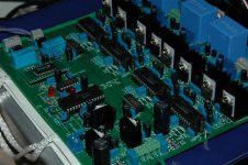
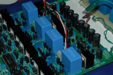
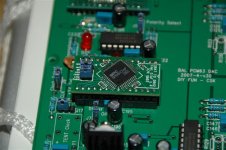
6. Thanks for all the support and I hope to receive more comment about this pcb. Thanks. Here is the update photo for reference.
1. The output level at balance mode is about 4Vrms which is too high for my pre-amp (DIY jfet SE pre-amp). Thus I put a 4.7k resistor in parallel to R4, R13, R24, & R34 (solder at the bottom side of pcb). This has no effect to the sound but match the sound level of my pre-amp volume control. Due to this change, all the pot R1, R10, R21, % R31 has to be re-adjust till Point A back to 10Vdc (half of the +ve voltage 20V).
2. I change the 4 output BIG film cap from Vishay 4u7 back to Rifa PHE 426 10uF 250V type. I found the sound improves a lot and sonic is more sweet and relax (less harsh). Thus you should consider to invest on better capacitor at the output coupling.
3. I change the DF from 5847 and 5842 back and fore and find that the 5842 did sound better to me (more relax). No wonder VC America sell the 5842 so high. There is also sonic difference between 5842AP and 5842APT chip, APT is a bit better.
4. My original testing is using a China make 20VA transformer of 24V x 2. I put in the Farnell 9531750 30VA 25V x 2 potted transformer, the pre-regulated voltage is about 30.5V and is very stable. Sonic wide is more stable and sound is more relax also. Anyway I also recommend to use Farnell 9531718 30VA 9Vx 2 transformer.
5. I believe this DAC has lots of potential for diyer to play around to get and improve to better sound. One idea is to use DIR9001 receive IC instead of 8414. 9001 has only 50ps jitter and thus I believe the sound should improve more. I don’t have this converter board yet and I may either build my own or buy one from China diy forum.
6. Thanks for all the support and I hope to receive more comment about this pcb. Thanks. Here is the update photo for reference.
Attachments

A separate Jfet IV with super low noise regulator pcb is on sales in trade post. See link below.
http://www.diyaudio.com/forums/showthread.php?s=&threadid=101874
http://www.diyaudio.com/forums/showthread.php?s=&threadid=101874
- Home
- Vendor's Bazaar
- NP D1 DAC clone with enhancement