You'll get six times the idle dissipation, so on ±30 V rails, you'll get ~18-20 W instead of 3ish W per channel. If you leave your MOD86 amp on at idle (no music) for a few hours and the heat sinks are more than 2-3 ºC warmer than the room, I'd get larger heat sinks for the MOD686.
I'm assuming 2x22 VAC @ 300 VA here. That's a wee bit underpowered if you intend to run the amp to clipping. If you're not changing your listening level by much, the 300 VA and 2x22000 uF will probably be OK.
Tom
Tom,
Thanks for explanation. I actually got 300VA,2x26VAC, so it should be fine.
As far as Guardian686 …
In my case I use transformers on the DAC output, so no way DC shows up at mod686 inputs.
Probability of lm3886 chip failure in mod686 is bit higher than in mod86, since mod686 uses six of them instead of one. Still the risk is relatively low in both cases.
Are there any other potential risks that mod686 has and mod86 does not, for which using Guarding686 makes sense?
Lastly is there any way one could match lm3886 to build mod686? Or this completely unnecessary?
I actually got 300VA,2x26VAC, so it should be fine.
2x26 VAC is perfect. 300 VA is a bit lower than what I normally recommend, but should be fine, especially if you don't run the amp continuously at clipping levels.
Probability of lm3886 chip failure in mod686 is bit higher than in mod86, since mod686 uses six of them instead of one. Still the risk is relatively low in both cases.
I agree.
Are there any other potential risks that mod686 has and mod86 does not, for which using Guarding686 makes sense?
Not that I can think of. The LM3886 is quite rugged. That said, it is pushed to its limits in the MOD686 and there are six of them.
Some like the protection circuits for the peace of mind they provide. They may have more expensive speakers than I do...
")
Lastly is there any way one could match lm3886 to build mod686? Or this completely unnecessary?
You could set up a test jig to match the LM3886es by their input offset voltage. Pick two pairs of three that have close to identical offset. If the three parallel LM3886es have the same offset, there'll be no error current flowing in the ballast resistors. That'll in theory give you slightly better performance near clipping.
In practice, there's no need for matching or binning the LM3886es, though.
Tom
Tom,
I have big case and I am considering using internal heatsinks for mod686.
I would like to also keep thermal resistance minimal, which means stick lm3886 to heatsinks directly. Heatsink will be totally detached from the metal case.
Is it possible to attached all of 6 lm3886 to one heatsink block without thermal pads? Or at least one heatsink block per phase (3xlm3886) without thermal pads?
Or maybe in case with no thermal pads each lm3886 would have to have its own detached heatsink form the rest? That would be tricky to do …
If you're going to push the thermal system, you'll want the metal-back LM3886T. As BrianL just noted, that means you'll get VEE on the heat sink. That's not a recipe for success generally. Also, with the Keratherm pads, there isn't much thermal resistance to worry about.
I think the folks who consider skipping the thermal pads are pushing at the wrong end of the equation. They'd be far better off just making the heat sink 5 mm taller.
The Modulus-686 requires a large heat sink. I consider the ModuShop 3U x 300 mm (0.4K/W) to be a minimum size heat sink for a Modulus-686 amp running on ±28 V. For ±36 V operation, you'll want the 4U x 300 or 5U x 300 mm heat sinks. Sorry man. Physics made me do it!
An alternative would be to use a 3U x 300 mm, ±36 V supply, and a 60-65 ºC thermal cutoff switch. You could probably argue that to be a "240 W, music power" amp. It'd run just fine at the new (2000-something) FTC test (1/8 of max output power for an hour) but will overheat in about 20-30 minutes with the 1974 FTC test (1/3 of max output power for an hour). It might last a little longer if the chassis is made of pretty think aluminum as well and can participate a bit as a heat sink.
Yet another alternative would be a cooling tunnel. These used to be quite common. They consisted of two heat sinks that came together in a 80x80 mm square with a hole of sorts in each corner where you'd attach an 80 mm fan. These days you can get some pretty quiet fans... That'd move some heat in a hurry.
Tom
Last edited:
If you're going to push the thermal system, you'll want the metal-back LM3886T. As BrianL just noted, that means you'll get VEE on the heat sink. That's not a recipe for success generally. Also, with the Keratherm pads, there isn't much thermal resistance to worry about.
I think the folks who consider skipping the thermal pads are pushing at the wrong end of the equation. They'd be far better off just making the heat sink 5 mm taller.
The Modulus-686 requires a large heat sink. I consider the ModuShop 3U x 300 mm (0.4K/W) to be a minimum size heat sink for a Modulus-686 amp running on ±28 V. For ±36 V operation, you'll want the 4U x 300 or 5U x 300 mm heat sinks. Sorry man. Physics made me do it!
An alternative would be to use a 3U x 300 mm, ±36 V supply, and a 60-65 ºC thermal cutoff switch. You could probably argue that to be a "240 W, music power" amp. It'd run just fine at the new (2000-something) FTC test (1/8 of max output power for an hour) but will overheat in about 20-30 minutes with the 1974 FTC test (1/3 of max output power for an hour). It might last a little longer if the chassis is made of pretty think aluminum as well and can participate a bit as a heat sink.
Yet another alternative would be a cooling tunnel. These used to be quite common. They consisted of two heat sinks that came together in a 80x80 mm square with a hole of sorts in each corner where you'd attach an 80 mm fan. These days you can get some pretty quiet fans... That'd move some heat in a hurry.
Tom
Seems like before "inventing" the physics everything was perfect, now it causes the trouble
Ok. got the point, however ... I already had the case and heatsinks that I could fit into it. They are ~0,5K/W each. So I thought if I skip thermal pads and use some good thermal grease instead I would gain some on lower thermal resistance and this is where my question came from.
Anyways I understand all of (six) lm3886 could be connected to one heatsink without thermal pads, I will get -36VDC on heatsinks, however eventually gain on lower thermal resistance would be minimal, right?
An alternative would be to use a 3U x 300 mm, ±36 V supply, and a 60-65 ºC thermal cutoff switch.
Hi Tom,
Does your ISS board support using thermostats? Would you just run the toggle switch wire through the thermal breakers on their way to the switch?
NF-R8 REDUX 1200RPM 80mm Quiet Case FanIf you're going to push the thermal system, you'll want the metal-back LM3886T. As BrianL just noted, that means you'll get VEE on the heat sink. That's not a recipe for success generally. Also, with the Keratherm pads, there isn't much thermal resistance to worry about.
I think the folks who consider skipping the thermal pads are pushing at the wrong end of the equation. They'd be far better off just making the heat sink 5 mm taller.
The Modulus-686 requires a large heat sink. I consider the ModuShop 3U x 300 mm (0.4K/W) to be a minimum size heat sink for a Modulus-686 amp running on ±28 V. For ±36 V operation, you'll want the 4U x 300 or 5U x 300 mm heat sinks. Sorry man. Physics made me do it!
An alternative would be to use a 3U x 300 mm, ±36 V supply, and a 60-65 ºC thermal cutoff switch. You could probably argue that to be a "240 W, music power" amp. It'd run just fine at the new (2000-something) FTC test (1/8 of max output power for an hour) but will overheat in about 20-30 minutes with the 1974 FTC test (1/3 of max output power for an hour). It might last a little longer if the chassis is made of pretty think aluminum as well and can participate a bit as a heat sink.
Yet another alternative would be a cooling tunnel. These used to be quite common. They consisted of two heat sinks that came together in a 80x80 mm square with a hole of sorts in each corner where you'd attach an 80 mm fan. These days you can get some pretty quiet fans... That'd move some heat in a hurry.
Tom
Does your ISS board support using thermostats?
It does. I put a 6-pin header on it that allows for a FAULT input. The header also has +5 V out, so a thermal switch (normally open type) could be connected from +5 V to FAULT. That'd shut the amp down gracefully when the temperature reaches the trip point of the thermostat.
Would you just run the toggle switch wire through the thermal breakers on their way to the switch?
Nah... That wouldn't work for those using a momentary power switch. It'd work for those with a toggle switch, though.
That's exactly what I had in mind. Many of the Noctura fans are in the single digit dB SPL.
Tom
Last edited:
Yet another alternative would be a cooling tunnel. These used to be quite common. They consisted of two heat sinks that came together in a 80x80 mm square with a hole of sorts in each corner where you'd attach an 80 mm fan. These days you can get some pretty quiet fans... That'd move some heat in a hurry.
The last amp I bought before getting into DIY was a QSC RMX2450 (link is for the newer "a" version, I had the pre-"a" one). I got it because this thread convinced me I needed such a beast.
Anyway, this amp does in fact have the cooling tunnel Tom describes. This amp is designed to power PA systems in a rack, where the volume is so loud the fan will be completely unnoticed. But since I was using it in a living room, my first job was to replace the fan with a low RPM model (of which I had many to draw from, given that building silent computers was/is another hobby of mine). Knowing what I know now about my power requirements, I'm certain I could have run it without any fan.
I eventually sold it on Craigslist. A couple Latino gentlemen showed up to buy it. During our brief chat, they said they already had another (or maybe two?) of the same model, and they were going to use it for music at a party. I said, "How big of a party? Do you really need this much power?"
With a room-filling smile, gentle nod, and perfectly matter-of-fact tone, he said, "It's a Mexican Party."
I stood confused for a second, until I realized that was his way of saying he likes it loud!
Seems like before "inventing" the physics everything was perfect, now it causes the trouble
As someone who spends his day pushing circuits as close to the boundaries set by physics, I can certainly attest that physics get in the way more often than not. Then again, silly things like gravity are sorta convenient.
With a room-filling smile, gentle nod, and perfectly matter-of-fact tone, he said, "It's a Mexican Party."
I stood confused for a second, until I realized that was his way of saying he likes it loud!
That's an excellent story.
Tom
Tom,
Well I am afraid 5U does not have enough WAF (Wife acceptance Factor). I think I could be easily kick out from living room to garage together with that case so, …
with 36VDC @ no load with 0.5k/W heatsinks per channel. Could I use SiC diodes for rectification?
Their dropping curve is bit different than from regular diodes. The more current goes through them the more voltage they drop. So at couple of Amps of current consumption they should drop around 2V each, which should give me around 32VDC on mod686 input. Eventually this should give me less heat generated on lm3886, obviously less power from amp and more heat generated on diodes heatsinks. So, in my case with 8ohms speakers with regular listening levels (I never go up to full volume anyway) it should be fine.
Putting economy aside (SiCs are expensive), do you think using SiC diodes is good idea in general? My concern is that speakers are not constant load and e.g.: mine dips into 3.7ohm at some frequencies, so when SiC are used they may introduce some voltage variations with high current consumptions spikes. On the other side however, as you say modulus686 is immune to that …
As far as physics and gravity some say that before Isaac Newton invented gravity people could actually fly
Well I am afraid 5U does not have enough WAF (Wife acceptance Factor). I think I could be easily kick out from living room to garage together with that case
so, …with 36VDC @ no load with 0.5k/W heatsinks per channel. Could I use SiC diodes for rectification?
Their dropping curve is bit different than from regular diodes. The more current goes through them the more voltage they drop. So at couple of Amps of current consumption they should drop around 2V each, which should give me around 32VDC on mod686 input. Eventually this should give me less heat generated on lm3886, obviously less power from amp and more heat generated on diodes heatsinks. So, in my case with 8ohms speakers with regular listening levels (I never go up to full volume anyway) it should be fine.
Putting economy aside (SiCs are expensive), do you think using SiC diodes is good idea in general? My concern is that speakers are not constant load and e.g.: mine dips into 3.7ohm at some frequencies, so when SiC are used they may introduce some voltage variations with high current consumptions spikes. On the other side however, as you say modulus686 is immune to that …
As far as physics and gravity some say that before Isaac Newton invented gravity people could actually fly
I'm not sure SiC diodes will do much good. If you closely compare V vs I curves for comparable Silicon and SiC diodes, you'll see not enough difference to be worth the cost. I doubt trusting the V vs I curve of SiC will ameliorate issue of LM3886 high-output dissipation very much.
The suggestion for a low-noise fan is a good one. Just a small amount of fan-induced air flow against a heat sink will help quite a bit.
Tom's suggestions for heat sinking are based on solid physics but also based on conservative assumptions about operation. See his resources pages for a more thorough discussion on the topic. It's likely that in a home audio setup you will only be putting out a lot of power on brief peaks, but that is dependent on your musical choices, speaker efficiency, listening levels, etc. Many people may not need the full conservative heat sinking, the problem being that if you use a smaller size and 'guess' wrong, you'll have a thermal problem that can only be resolved by a new, bigger chassis/heatsink.
The idea of some sort of temperature sensing and shutdown is a very good idea even if you follow the conservative recommendations for thermal management.
If you get ±36 V at idle with nominal or high mains voltage, I'd leave the supply as-is. If you're worried about the power dissipation in the heat sink, go with a 2x24 VAC transformer or 2x22 VAC transformer. That'll give you closer to ±30 V and ±32 V, respectively.
My heat sink recommendations for music reproduction are based on ±36 V supply voltage, 14 dB crest factor, 4 Ω load, 25 ºC ambient temperature, and 60 ºC heat sink temperature. I do not find this to be a conservative estimate. It's certainly a more conservative estimate than many commercial outfits appear to use. I would rather err on the side of caution than have an amp that self-destructs or - worse - harms people or pets. The LM3886 also provides better performance (lower THD) at lower case temperatures due to the SPiKe protection.
My standard test is to run the amp for an hour or two with a 4 Ω load and the AP 32-tone test signal applied at a level that's just below clipping. That's equivalent to running music with a 10 dB CF at clipping levels. My 0.4 K/W rated heat sinks reach over 65 ºC after about 30 minutes with the MOD686 at ±36 V. That's in a relatively cool lab (18-20 ºC).
The 3U x 300 mm Dissipante heat sinks are enough for ±28 V operation. Jump to the 4U x 300 mm for ±36 V. Or use the 3U and add a 60-65 ºC thermal cutoff.
That said, these numbers do not account for the rest of the chassis. If you're using a chassis with a 10 mm aluminum front and 2-3 mm thick panels, the chassis itself will participate as a heat sink as well. So it may be that the 3U Dissipante chassis is enough for ±36 V operation in practice. I'll have a more definitive answer to that within the next couple of weeks.
Tom
Brain, Tom, Casull thanks for your support. I was thinking of fun as last resort, but the more I think about the more I am convincing my self that pesante dissipante case is the way to go. Especially because from what I see hole spacing in mod686 are aligned for this radiator. Thanks!
The locations of the LM3886es or the holes in the mounting bracket were not designed for any specific heat sink. They were driven entirely by the layout.
The ModuShop Pesante is not a good fit for the MOD686 as it does not feature an external heat sink. It's the Dissipante series that I'm recommending. The 4U and 3U Dissipante and 3U Mini Dissipante (300 mm depth and beyond) are strong chassis candidates for the MOD686.
Tom
The ModuShop Pesante is not a good fit for the MOD686 as it does not feature an external heat sink. It's the Dissipante series that I'm recommending. The 4U and 3U Dissipante and 3U Mini Dissipante (300 mm depth and beyond) are strong chassis candidates for the MOD686.
Tom
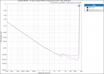
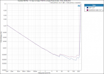
The Guardian-686 boards have arrived and are available for sale. It does cause an ever-so-slight rise in THD towards the higher output powers, but the overall THD of the MOD686+Guardian-686 is still better than most amps on the market (and on par with the Benchmark ABH-2 if I recall their measurements correctly).
Tom
Tom
Attachments
Last edited:
I have also put together a little board for connecting and controlling two Mean Well EPP-300, EPP-400, RPS-300, or RPS-400 power supplies to form the split/dual supply needed for an audio amp. The board features:
The boards should be here tomorrow or Wednesday. Yay!
Tom
- Easy connection to two Mean Well EPP/RPS 300/400 series power supplies creating a dual supply suitable for audio amplifiers.
- Remote sensing eliminates the voltage drops across connecting wires and PCB layout.
- Power output provided on Molex Mega-Fit and JST connectors for easy connection to the Neurochrome Modulus amplifiers.
- Connection to a momentary power switch, such as the many anti-vandal switches popular in DIY audio circles.
- Support for both two-pin bi-colour and regular LEDs for ON/STANDBY indication.
- Optically isolated 12 V trigger input.
- Six-pin header connector allowing for connection to protection circuits, signal-detect circuits, etc.
- Elaborate use of copper planes and pours to ensure the best circuit performance.
- 4.00 × 1.75 inch board footprint. The finished module measures approx. 20 mm in height.
The boards should be here tomorrow or Wednesday. Yay!
Tom
Hi Tom,
I’d assume i would need two guardian 686’s?
Also, would migrating from my ISS to this new board specifically designed for the meanwell supplies make sense?
With 4 RPS400-36 in my unit i am using the current ISS as a soft start to prevent the current inrush from all 4 smps’s at the same time.
Thanks!
I’d assume i would need two guardian 686’s?
Yep. You'll need one Guardian-686 per Modulus-686 board.
Also, would migrating from my ISS to this new board specifically designed for the meanwell supplies make sense?
Perhaps. The new board is much smaller - about half the size of the ISS, so it may be easier to fit in the chassis.
The Mean Well Control does not support the use of a toggle power switch. Only momentary switches (think doorbell switches) are supported (along with the 12V trigger). With two boards, it'll be easiest to use a dual-pole switch - one pole for each board. I think I can figure out a way to daisy chain them, though.
With 4 RPS400-36 in my unit i am using the current ISS as a soft start to prevent the current inrush from all 4 smps’s at the same time.
You'll have some inrush when you first plug the supplies in. That's just their input capacitors charging. That's not anything I normally worry about. The supplies turn on/off by controlling a 5V logic input. I am fairly certain that they start up gently. That's a pretty common feature. I've certainly never seen them dim the lights or anything like that.
The Mean Well Control board uses surface mounted components. 0805 size or larger. For the time being I'll offer the bare boards so you can assemble them yourself.
Another advantage of the Mean Well Control boards is that the outputs are provided on Molex Mega-Fit connectors, thus are easy to connect to the Modulus-686. It's literally plug-and-play.
Tom
- Home
- Vendor's Bazaar
- Modulus-686: 380W (4Ω); 220W (8Ω) Balanced Composite Power Amp with extremely low THD