Pete, I bought one of your Korg HP amp boards recently. Finally got around to building it last night, took about two hours. Your attention to detail was appreciated. Reminded me of when I built Heathkits back in the day.
Applied power and everything works. I have been enjoying listening to it this past hours. Yours is great, a nice addition to several other class A headphone amps I now have.
Thank you again for your skills and time.
David
Applied power and everything works. I have been enjoying listening to it this past hours. Yours is great, a nice addition to several other class A headphone amps I now have.
Thank you again for your skills and time.
David
How does this nutube compare to a regular triode? I would like to hear some listening opinions of itI wonder if this would make a good fit with the tpa3255 I own?? I have a pentode tube amp that does voices and instruments really good, but it doesn't have the power that the tpa3255 has. Therefore I'm looking into making a hybrid amp with the tpa3255. With the lifetime of the nutube and the clean tpa3255 it could be an interesting mix.
Look at post 28.
For just line signal remove output IC LME49600 of my schematic.
Pete, I purchased the Korg Nutube evaluation board from you (not sure of my soldering chops) and I'm awaiting delivery. I have no doubts that your kit is significantly better, that said how does the eval board sound? Is the sonic character similar? I look forward to putting it in an enclosure and enjoying it. It sounds like I'll be able to adjust the bias and dial in more tube goodness if I want.
Regards,
Walt
Regards,
Walt
Pete Buffer question
I got one of your buffers up and running and i am noticing the buffer has developed a strong hissing sound on one channel the other channel hisses as well but not so much. I don't have an oscilloscope right now so i can't see the noise as i set the bias. I set the bias at 2V over C4 and C10 is this the correct measuring point? and what is your recommended setting. I am using a battery 12.7V
I don't recall having this strong hiss when i first listened to the buffer, it was there for sure but not as much.
It might be oscillating. If you used a FET for the input buffers (2N7000) as opposed to a bipolar (2N3904) - it can break into oscillation when driven from a low impedance source.
If so... you can fix it by adding a ~1k resistor in series with the gate, or by swapping the FET for a bipolar.
Usually I set the bias by measuring the voltages on the Nutube plates, and setting them to be about 1/2 the supply voltage.
Pete
If so... you can fix it by adding a ~1k resistor in series with the gate, or by swapping the FET for a bipolar.
Usually I set the bias by measuring the voltages on the Nutube plates, and setting them to be about 1/2 the supply voltage.
Pete
Thank you Peter
I tried putting in a 1.5k resistor at the input, that's all I had didn't help. I was looking at your schematic R8,9 should be 330K for 12V that i am running not 475k that I have there now.
I will order the 330K resistors and some 1K just in case and the input buffers 2N3904 to see if that works, I hope I didn't break it.
Last edited:
Bias
Hello All,
I just put together the Nutube Buffer kit from Pete. This is my first electronics project and my knowledge is very limited. So, limited that I put the small caps in reverse polarity because I did not know any better and didn't realize what the dots on the board meant I have it powering up with a 12v 5ma battery. I don't, however, know how to measure voltage when adjusting bias with the trim pots. Also, I know that there is an oscillation issue that Pete told me to solder a 1k resistor in series to the plate of the Nutube, but I am not sure where on the board to do that.
Thanks ahead of time with any help!! I thought this would be a good starter project but there are still a lot of things that I need to learn.
Hello All,
I just put together the Nutube Buffer kit from Pete. This is my first electronics project and my knowledge is very limited. So, limited that I put the small caps in reverse polarity because I did not know any better and didn't realize what the dots on the board meant
I have it powering up with a 12v 5ma battery. I don't, however, know how to measure voltage when adjusting bias with the trim pots. Also, I know that there is an oscillation issue that Pete told me to solder a 1k resistor in series to the plate of the Nutube, but I am not sure where on the board to do that. Thanks ahead of time with any help!! I thought this would be a good starter project but there are still a lot of things that I need to learn.
I have just finished mine. Sounds great!!
Microphonic it is... And the Pot in the BOM needs to be upgraded which i will.
Was first curious how it sounded.
@enochrome
I hope you have the caps right now? You measure the voltage between the opamps.
Tp3 is ground
Tp2 is right channel
Tp1 left channel
Measure with multimeter on ground and Tp2 and adjust the screw. Please note there can be lot of turns on the screwdriver before you see changes.
And that. Ground Tp1 the same around 11V
Here is the note on oscillation.
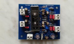
Nutube 6P1 Buffer PCB
Microphonic it is... And the Pot in the BOM needs to be upgraded which i will.
Was first curious how it sounded.
@enochrome
I hope you have the caps right now? You measure the voltage between the opamps.
Tp3 is ground
Tp2 is right channel
Tp1 left channel
Measure with multimeter on ground and Tp2 and adjust the screw. Please note there can be lot of turns on the screwdriver before you see changes.
And that. Ground Tp1 the same around 11V
Here is the note on oscillation.
Nutube 6P1 Buffer PCB
Last edited:
Thanks Volvola and Detectit1 for helping me out! I am still at work, so can't post photos till later. I did fix the caps (embarrassing) and now they are orientated the right way. My board looks like Pete's on his website ( but with solder marks )
Detectit1, I don't see any Tp1 or Tp2 on the boards and there are no opamps. Are you talking about the headphone board?
Where I'm at now is:
1. Everything is put together and it powers up. The tubes charge.
2. I understand that the trim pots adjust bias. I have no idea how to check bias? Where do you measure this for the Nutube buffer board? Is it at the left and right outputs?
3. I would like to get 1.5 thd at 1v based on how Nelson Pass biased his Nutube buffer pre. This will give me a great base for comparison.
4. Pete told me to solder a 1k resistor in series to the plate of the actual Nutube. I don't know where the plate is and how to solder the resistor in series?
These four things pretty much show you that I am starting from the ground floor, so I apologize if you have to over explain or repeat. I am extremely grateful for the help.
) Detectit1, I don't see any Tp1 or Tp2 on the boards and there are no opamps. Are you talking about the headphone board?
Where I'm at now is:
1. Everything is put together and it powers up. The tubes charge.
2. I understand that the trim pots adjust bias. I have no idea how to check bias? Where do you measure this for the Nutube buffer board? Is it at the left and right outputs?
3. I would like to get 1.5 thd at 1v based on how Nelson Pass biased his Nutube buffer pre. This will give me a great base for comparison.
4. Pete told me to solder a 1k resistor in series to the plate of the actual Nutube. I don't know where the plate is and how to solder the resistor in series?
These four things pretty much show you that I am starting from the ground floor, so I apologize if you have to over explain or repeat. I am extremely grateful for the help.
- Status
- This old topic is closed. If you want to reopen this topic, contact a moderator using the "Report Post" button.
- Home
- Vendor's Bazaar
- Korg NuTube is now available online