I worked alot to build this one (just 10 modules made), is all in one amplifier ClassAB+B, (initially it was one ClassH prototype but I quit on that and keep AB+B class).
Each module contains balanced to unbalanced stage, IOC limiter (input output comparator limiter), thermal protection, overload and shorted output protection, auto fan based on heatsink temperature DC out protection (triac crowbarr), missing supply rail protection.
This amp is stable 2 ohms, and output current capability is around 50Amps RMS, limited by overload at 39Amps RMS.
Is based on Leco SMPS, custom version for 5,5Kwatts.
I have measured on dummy load as seen in videos (all are in Romanian language but is easy to see and understand what I have done there).
Bottom side
http://s13.postimg.org/6sjsj7qbb/Leco_V3_Bottom.jpg
Top side
http://s13.postimg.org/5g23hbsvr/Leco_V3_Top.jpg
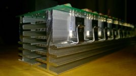
Output stage
View image: Output stage
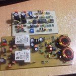
Some components mounted
View image: DSCN2157
View image: DSCN2158
View image: DSCN2159
On all following tests, the cooling was very poor, one small fan just move the air!
Output current capability on 1 ohm dummy load:
https://www.youtube.com/watch?v=7N9bGpcKHrs
Thermal limiting and main supply current draw from soket wall at 1 ohm load:
https://www.youtube.com/watch?v=vXiCzzpsfnk
Output current capability on 2 ohms and thermal limiting:
https://www.youtube.com/watch?v=7CGDSu9w_IE
Some scope captures:
Sinusoidal 10kHz:
View image: 1 10k Hz Sin
Triangular 10kHz:
View image: 2 10k Hz Tri
Rise-Fall Times on 8 ohms dummy:
View image: 3 10k Hz Rise Fall Times Dupa Bobina
8 ohms+1uF capacitive load on 10kHz squarewave:
View image: 5 10k Hz 1u F Capacitiv
8 ohms+1uF capacitive load on 10kHz squarewave detail:
View image: 6 10k Hz 1u F Capacitiv Detaliu
Maximum out voltage before clipping 8 Ohm on 10kHz sinusoidal:
View image: 7 10k Hz Vrms Max 8 Ohm
Maximum out voltage before clipping 8 Ohm on 10kHz squarewave:
View image: 8 10k Hz Out Max Drept Cu 8 Ohm Load
Max level then shorted output:
View image: 9 Limitare La Scurt Pe Iesire
And now movies of above scope captures:
Leco V3 rise and fall times +capacitive load:
https://www.youtube.com/watch?v=b3aRnI0nfO4&feature=youtu.be
Leco V3 maximum output on sinusiodal and squarewave signal:
https://www.youtube.com/watch?v=BWNUFg5dgnQ&feature=youtu.be
Leco V3 reactive load 1000Hz 8 Ohm+143uH:
https://www.youtube.com/watch?v=Y4xE_w7JCWE&feature=youtu.be
Leco V3 shorted output and overload: (nice movie!!!)
https://www.youtube.com/watch?v=LH6TSYm7QTI&feature=youtu.be
During tests it was one scope probe uncalibrated, so now is OK
1000Hz probes compensation:
View image: Sonde compensate la 1k Hz
10000Hz probes compensation:
View image: Sonde compensate 10khz
212Vpp between 10% and 90% in squarewave at 10kHz on 8 ohm load, 3,6uSec rise time:
View image: 10 90% 212 Vpp
Max out in squarewave at 10kHz capacitive load 1uF on output:
View image: 10khz Max out cu 1u F la iesire
Clean output at 100Hz on 8 ohm dummy load on output, almost 860 watts (yeloow is output signal, blue is input signal):
View image: Vmax out la 100 Hz 8 Ohm
Clean output at 100Hz on 2 ohm dummy load on output, almost 2300 watts (yeloow is output signal, blue is input signal):
View image: Vmax out la 100hz 2 Ohm
And movies of above scope captures:
1000 and 10000Hz probes compensation:
https://www.youtube.com/watch?v=45bljGxShas&feature=youtu.be
Leco V3 Amplifier Slew Rate Test+1uF Capacitor:
https://www.youtube.com/watch?v=_XRtqYWGOuI&feature=youtu.be
Leco V3 At Output 83-84Vrms/8Ohm Load:
https://www.youtube.com/watch?v=sRbl-yiexkY&feature=youtu.be
Leco V3 At Output 77-78Vrms/4Ohm Load:
https://www.youtube.com/watch?v=vOWOysoFKD0&feature=youtu.be
Leco V3 At Output 67-68Vrms/2 Ohm @ 224Vac
https://www.youtube.com/watch?v=I_Q4Lr38iXk&feature=youtu.be
Leco V3 Damping Factor At 8 Ohm 100Hz (it falls around 2-3mV when load connected, DF more than 6000)
https://www.youtube.com/watch?v=PLVYt5XFL_c&feature=youtu.be
Input Output Comparator limiter in action on 8/4/2 ohms loading:
https://www.youtube.com/watch?v=_f-4JvsPS6o
Linearity in Hi Freq 1000 to 60000Hz at 450W rms until above 0,05% THD or more appears (red led is flashing):
https://www.youtube.com/watch?v=Ot1jPkRdnQ0
Linearity from 5Hz to 200000Hz at 150 and 100watts/8 ohms:
https://www.youtube.com/watch?v=lSMabN6qM5o&feature=youtu.be
Some pictures during final assembly:
http://postimg.org/image/h4hsy8q9x/
http://postimg.org/image/cnpfzkc1x/
http://postimg.org/image/q9q5s3tol/
http://postimg.org/image/tum1bby85/
http://postimg.org/image/5up33al8l/
http://postimg.org/image/objhu416t/
http://postimg.org/image/dm5t1updx
Testing at home on mine top speakers:
https://www.youtube.com/watch?v=qKv0pJ1Er44&feature=youtu.be
His first event, played flawless and very clean audio:
https://www.youtube.com/watch?v=DNovsvt_N-k&feature=youtu.be
Each module contains balanced to unbalanced stage, IOC limiter (input output comparator limiter), thermal protection, overload and shorted output protection, auto fan based on heatsink temperature DC out protection (triac crowbarr), missing supply rail protection.
This amp is stable 2 ohms, and output current capability is around 50Amps RMS, limited by overload at 39Amps RMS.
Is based on Leco SMPS, custom version for 5,5Kwatts.
I have measured on dummy load as seen in videos (all are in Romanian language but is easy to see and understand what I have done there).
Bottom side
http://s13.postimg.org/6sjsj7qbb/Leco_V3_Bottom.jpg
Top side
http://s13.postimg.org/5g23hbsvr/Leco_V3_Top.jpg
Output stage
View image: Output stage
Some components mounted
View image: DSCN2157
View image: DSCN2158
View image: DSCN2159
On all following tests, the cooling was very poor, one small fan just move the air!
Output current capability on 1 ohm dummy load:
https://www.youtube.com/watch?v=7N9bGpcKHrs
Thermal limiting and main supply current draw from soket wall at 1 ohm load:
https://www.youtube.com/watch?v=vXiCzzpsfnk
Output current capability on 2 ohms and thermal limiting:
https://www.youtube.com/watch?v=7CGDSu9w_IE
Some scope captures:
Sinusoidal 10kHz:
View image: 1 10k Hz Sin
Triangular 10kHz:
View image: 2 10k Hz Tri
Rise-Fall Times on 8 ohms dummy:
View image: 3 10k Hz Rise Fall Times Dupa Bobina
8 ohms+1uF capacitive load on 10kHz squarewave:
View image: 5 10k Hz 1u F Capacitiv
8 ohms+1uF capacitive load on 10kHz squarewave detail:
View image: 6 10k Hz 1u F Capacitiv Detaliu
Maximum out voltage before clipping 8 Ohm on 10kHz sinusoidal:
View image: 7 10k Hz Vrms Max 8 Ohm
Maximum out voltage before clipping 8 Ohm on 10kHz squarewave:
View image: 8 10k Hz Out Max Drept Cu 8 Ohm Load
Max level then shorted output:
View image: 9 Limitare La Scurt Pe Iesire
And now movies of above scope captures:
Leco V3 rise and fall times +capacitive load:
https://www.youtube.com/watch?v=b3aRnI0nfO4&feature=youtu.be
Leco V3 maximum output on sinusiodal and squarewave signal:
https://www.youtube.com/watch?v=BWNUFg5dgnQ&feature=youtu.be
Leco V3 reactive load 1000Hz 8 Ohm+143uH:
https://www.youtube.com/watch?v=Y4xE_w7JCWE&feature=youtu.be
Leco V3 shorted output and overload: (nice movie!!!)
https://www.youtube.com/watch?v=LH6TSYm7QTI&feature=youtu.be
During tests it was one scope probe uncalibrated, so now is OK
1000Hz probes compensation:
View image: Sonde compensate la 1k Hz
10000Hz probes compensation:
View image: Sonde compensate 10khz
212Vpp between 10% and 90% in squarewave at 10kHz on 8 ohm load, 3,6uSec rise time:
View image: 10 90% 212 Vpp
Max out in squarewave at 10kHz capacitive load 1uF on output:
View image: 10khz Max out cu 1u F la iesire
Clean output at 100Hz on 8 ohm dummy load on output, almost 860 watts (yeloow is output signal, blue is input signal):
View image: Vmax out la 100 Hz 8 Ohm
Clean output at 100Hz on 2 ohm dummy load on output, almost 2300 watts (yeloow is output signal, blue is input signal):
View image: Vmax out la 100hz 2 Ohm
And movies of above scope captures:
1000 and 10000Hz probes compensation:
https://www.youtube.com/watch?v=45bljGxShas&feature=youtu.be
Leco V3 Amplifier Slew Rate Test+1uF Capacitor:
https://www.youtube.com/watch?v=_XRtqYWGOuI&feature=youtu.be
Leco V3 At Output 83-84Vrms/8Ohm Load:
https://www.youtube.com/watch?v=sRbl-yiexkY&feature=youtu.be
Leco V3 At Output 77-78Vrms/4Ohm Load:
https://www.youtube.com/watch?v=vOWOysoFKD0&feature=youtu.be
Leco V3 At Output 67-68Vrms/2 Ohm @ 224Vac
https://www.youtube.com/watch?v=I_Q4Lr38iXk&feature=youtu.be
Leco V3 Damping Factor At 8 Ohm 100Hz (it falls around 2-3mV when load connected, DF more than 6000)
https://www.youtube.com/watch?v=PLVYt5XFL_c&feature=youtu.be
Input Output Comparator limiter in action on 8/4/2 ohms loading:
https://www.youtube.com/watch?v=_f-4JvsPS6o
Linearity in Hi Freq 1000 to 60000Hz at 450W rms until above 0,05% THD or more appears (red led is flashing):
https://www.youtube.com/watch?v=Ot1jPkRdnQ0
Linearity from 5Hz to 200000Hz at 150 and 100watts/8 ohms:
https://www.youtube.com/watch?v=lSMabN6qM5o&feature=youtu.be
Some pictures during final assembly:
http://postimg.org/image/h4hsy8q9x/
http://postimg.org/image/cnpfzkc1x/
http://postimg.org/image/q9q5s3tol/
http://postimg.org/image/tum1bby85/
http://postimg.org/image/5up33al8l/
http://postimg.org/image/objhu416t/
http://postimg.org/image/dm5t1updx
Testing at home on mine top speakers:
https://www.youtube.com/watch?v=qKv0pJ1Er44&feature=youtu.be
His first event, played flawless and very clean audio:
https://www.youtube.com/watch?v=DNovsvt_N-k&feature=youtu.be
Last edited:

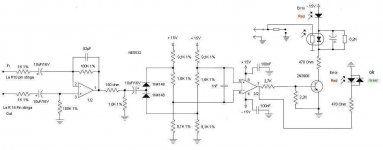
The working principle is to take signal from input final stage and from output final stage too (divided corectly too), and when mismatching, it acts, on balanced input stage to cut the input signal.
Crown uses error amplifier stage for IOC
That's not the schematic that I use, the schematic above is a joke, longtime ago.
Crown uses error amplifier stage for IOC
That's not the schematic that I use, the schematic above is a joke, longtime ago.
Attachments
Last edited:
The working principle is to take signal from input final stage and from output final stage too (divided corectly too), and when mismatching, it acts, on balanced input stage to cut the input signal.
Crown uses error amplifier stage for IOC
That's not the schematic that I use, the schematic above is a joke, longtime ago.
http://www.diyaudio.com/forums/solid-state/221737-ultimate-amp-protection-circuit.html?highlight=ultimate
Sorry for that but it was made exclusive for this project, I cannot share.
Generally short protection, limits output current at maximum value limited, as you see, at mine amplifier, it cuts from 30-40A rms on output to 1,8Arms, wich minimise dissipation, also limiter cuts off signal toi minimum, if error persists.
Is a multislope protection.
Generally short protection, limits output current at maximum value limited, as you see, at mine amplifier, it cuts from 30-40A rms on output to 1,8Arms, wich minimise dissipation, also limiter cuts off signal toi minimum, if error persists.
Is a multislope protection.
presumming volume knob is not at maximum (as must be).
I hate the volume knobs, so I not use them in my amplifiers, only if specially requested.
Sajti
 This appears to be commercially oriented since schematics and other details have not been shared and there is a statement to the effect that they cannot be shared. Posting commercial projects to the general forums is only OK if all details required to construct a working copy are also shared with the membership.
This thread will be moved to the vendors forum.
- Status
- This old topic is closed. If you want to reopen this topic, contact a moderator using the "Report Post" button.
- Home
- Vendor's Bazaar
- Mine Leco V3 Power Amplifier