Thanks Scott. I'm still thinking about circuits for hybrid amps, and I hope you don't mind if I ask a few more questions about yours.
Is it really direct-coupled - if a DC voltage is applied to the input, is it transferred to the output? I think I see some Jensen audio transformers in your photo.
If so, how is the DC offset at the output controlled? Is there an offset correction servo? How stable is the output offset?
There are many ICs and transistors on the PCB. What parts of your circuit are tube, and what parts transistors?
Thanks,
Iwan
Hi Iwan,
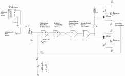
Yes, it is really direct coupled, from the input stage to the output. But between the input connector and the input stage is either a DC blocking capacitor (in the case of the unbalanced RCA inputs), or a Jensen line-balancing transformer. Most direct-coupled transistor amps work the same way - they use a DC blocking cap at the input, to prevent a DC offset from your source from reaching the speakers.
The offset at the output is set by the input stage, which is a 5751 (a 12AX7 variant) differential pair. The offset is trimmed to within +/- 0.02V with a pot in the cathodes of the input diff pair. The amp is protected from excess DC offsets the same way that a transistor amp is: offsets greater than a predetermined amount open an output relay.
There is no offset correction servo. That was one of my motivations for direct coupling the amp. In an AC-coupled hybrid amp with a servo, the two feedback loops fight each other and slow recovery from overloads.
A number of these amps have been in service for almost three years now, and offsets are maintained < +/- 0.05V and are monitored by a microcontroller.
The output stage uses bipolar Sziklai pairs, as well as a bunch of transistors for biasing. The rest of the signal path is tubes - but the tubes do have current-source or current mirror loads in the 2nd an 3rd stages. And there are a bunch of solid state devices used in control circuits.
Hope that is useful. I could draw a block diagram, if you give me a few days.
Best,
Scott
Thanks again Scott. As much as you might be willing to share of the block diagram is very helpful for my thinking. Iwan
Hi Iwan,
I updated the Minotaur owner's manual to include a block diagram. That was a good idea. I'll also attach it to this post.
Minotaur Direct-Coupled Hybrid Integrated Amplifier – Tavish Design
Scott
Attachments
Thanks!! I could build that. I assume you used split +/- HV supplies to direct couple that?
Iwan
Yes, correct. +320V / -160V for the tube sections, +/-50V for the output stage. Scott
Hi Scott
Can you tell me the values of c5 & r15 please
does ic3 need to be insulated from heat sink?
Thanks Paul,
C5 is 470uF 25v electrolytic w/ a 5mm lead space. R15 is 100 ohms, 1 W, 5%. Both are correct in the schematic but somehow got omitted from the parts list. They are correct on the 4P1 version of the manual, which is now the one on the website. And, no insulation needed for the heatsink.
Sorry for the errors. It is difficult to come to the end of manual corrections, and somehow I edited IN those errors since version 2...... My son is taking photos of his latest build and I'll update the manual again with the latest photos when he is finished.
Scott
Thanks Scott, nearly finished, but the output connections seem to be earthed?
Cant see anything obvious wrong.
Haven't powered it yet.
Hi Paul,
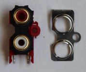
The output connectors should not be connected to the chassis, if that is what you're asking. There is a photo in the assembly manual showing how to remove the metal ground piece and expose an insulator - I attached it here.
Best,
Scott
Attachments
Ok once it powers up and the relay kicks in it stops grounding the signal.
Next problem, im not getting enough power. With the fuse out I get 18.6 dcv at p18. With the fuse in it is 17.5. HV pad is about 170vdc and dropping.
Also 400ma fuse blows occasionally, 800ma is fine. (only turned on for short periods)
I can get a 24 acv (0.9 amp or 1.87a) power plug would that work?
I cant get any sound when I hook it all up, Im assuming that it due to lack of power?
Ok once it powers up and the relay kicks in it stops grounding the signal.
Next problem, im not getting enough power. With the fuse out I get 18.6 dcv at p18. With the fuse in it is 17.5. HV pad is about 170vdc and dropping.
Also 400ma fuse blows occasionally, 800ma is fine. (only turned on for short periods)
I can get a 24 acv (0.9 amp or 1.87a) power plug would that work?
I cant get any sound when I hook it all up, Im assuming that it due to lack of power?
Hi Paul,
Sorry you are having trouble. I'm happy to hep you troubleshoot it. You may be the first person to build it with other than the transformers specified in the parts list, but I'm sure we can make it work.
If the unregulated 21v supply is too low, the output will be muted by the relay, so that is almost certainly the problem.
Can you measure the raw (~ +21v supply) with the fuse out, then with it in? Then measure the raw high voltage supply, with the fuse in? Can you send me a photo of your board? Don't try a higher voltage for the wall transformer yet - we first need to understand what's happening. It sounds like it may be excessively loaded by the HV supply.
Be very careful when measuring things on the board. Connect the negative lead of your voltmeter to the AGND pad on the PCB and keep one hand in your pocket as you measure. The most important thing with tubes is not to get a shock!
Troubleshooting will be faster if you contact me by email: info@tavishdesign.com. We can still keep the thread updated with your progress.
Best regards,
Scott
Updated Classic Phono Assembly Manual
Hi Everyone,
I’ve just updated the Classic Phono Assembly Manual on our website. The new manual has an updated sequence of assembly photos.
And, I’ve added a new section “DIY FAQ” for the benefit of DIYers building the phono stage without the kit. It includes some guidance on parts substitutions, finding parts, and powering the board outside North America. It is based mostly on questions we’ve answered by email, and we’ll update it as more questions arise.
We also have a new product on our website, our Adagio Phono Stage, to be available soon.
Best regards,
Scott
2nd Raffle Winner
Hi Everyone,
We’ve picked our second diyaudio raffle winner, for a Classic Phono Stage PCB (including free shipping). The winner has been notified by PM.
The raffle winner is chosen randomly from all those who post a question, suggestion, or constructive comment on Tavish Design’s vendor thread(s). Odds of winning are pretty high.
The next raffle will be held in about a month (probably after the New York Audio Show). Those who did not win this month are reentered next month. Winners can only win once.
Best,
Scott
Hi everyone,
I’ve just updated the Classic Phono Stage Assembly and Setup Manual on our website. The updates are all in the “DIY FAQ” section, where I’ve posted a few more questions that we’ve gotten by email (including a question about the cathode-bypass capacitor in the first stage).
Are there any readers in the NY area?
Tavish Design will be exhibiting at the 2015 New York Audio Show in Rye, NY (Friday Nov 6th to Sunday Nov 8th), Room 4016. It's a great opportunity to see and hear our equipment, push the buttons, and ask questions. You can see and hear our Minotaur Hybrid Amplifier and Classic Phono Stage, and we'll be introducing a couple of new products as well, including our Adagio Phono Stage.
You can get a 10% discount on show attendance with the code: TDNYAS10%
Scott
Tavish Design will be exhibiting at the 2015 New York Audio Show in Rye, NY (Friday Nov 6th to Sunday Nov 8th), Room 4016. It's a great opportunity to see and hear our equipment, push the buttons, and ask questions. You can see and hear our Minotaur Hybrid Amplifier and Classic Phono Stage, and we'll be introducing a couple of new products as well, including our Adagio Phono Stage.
Out in the Midwest for a board meeting that week, too bad, it would be great to meet up.
Hi Scott,
Good to see your thread active. I’ve run a spice simulation of a direct coupled tube-mosfet amplifier, based on your block diagram, and also based on your headphone amplifier schematic. I couldn’t see exactly how the driver stage in your block diagram was direct coupled, so my circuit looks more like a 2 stage version of your headphone amp. It all works. It’s possible to direct couple a multistage amp using split supplies and your level shifter. I’m intrigued.
One thing I can’t simulate is the DC offset stability. As I understand your circuit, the output DC offset depends on the input stage DC offset. You say that the offset can be adjusted to less than 20mV, but how often does it need to be readjusted to keep it there? Is it only a manual adjustment, or does your microcontroller adjust the offset? How much offset do you think is reasonable?
Iwan
Hi Iwan,
And good to hear there is someone else interested in hybrid amp circuits like this…… Feel free to contact me by email or PM if you decide to build something and have specific questions about your circuit.
For the Minotaur, DC offset in the input diff pair is a manual adjustment; the microcontroller monitors the output offset and alerts the user if it exceeds 50mV, but there are no automated adjustments.
I don’t have extensive data on long-term offset drift, but the data I do have suggest that the offset may only need readjustment when replacing the input tube (5751).
I built my initial prototype in 2011, and some “early adopters” have been using the Minotaur since 2012. No user has reported an indication of offset >50mV. The highest long-term offset drift I’ve measured is ~25mV on one channel of my initial prototype, and I believe our current amplifiers are better, because I now select input 5751 tubes with well-matched sections, and I also discard tubes that show bias drift during burn-in.
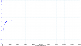
As part of our burn-in process, I adjust the offset to <10mV, then monitor the offset post burn-in to make sure it is stable. The attached plot shows the offset over a 2+ hour time period. After the first 5 minutes, the offset settles to ~+3mV and stays there. Not all samples are quite so good as this, but even some solid-state amps aren’t as good. This degree of offset stability is only possible with regulated HV and heater supplies.
Of course, the long-term drift of any specific tube is impossible to predict. At any rate, I think these offsets are too small to affect either the amplifier or a loudspeaker.
Best regards,
Scott
And good to hear there is someone else interested in hybrid amp circuits like this…… Feel free to contact me by email or PM if you decide to build something and have specific questions about your circuit.
For the Minotaur, DC offset in the input diff pair is a manual adjustment; the microcontroller monitors the output offset and alerts the user if it exceeds 50mV, but there are no automated adjustments.
I don’t have extensive data on long-term offset drift, but the data I do have suggest that the offset may only need readjustment when replacing the input tube (5751).
I built my initial prototype in 2011, and some “early adopters” have been using the Minotaur since 2012. No user has reported an indication of offset >50mV. The highest long-term offset drift I’ve measured is ~25mV on one channel of my initial prototype, and I believe our current amplifiers are better, because I now select input 5751 tubes with well-matched sections, and I also discard tubes that show bias drift during burn-in.
As part of our burn-in process, I adjust the offset to <10mV, then monitor the offset post burn-in to make sure it is stable. The attached plot shows the offset over a 2+ hour time period. After the first 5 minutes, the offset settles to ~+3mV and stays there. Not all samples are quite so good as this, but even some solid-state amps aren’t as good. This degree of offset stability is only possible with regulated HV and heater supplies.
Of course, the long-term drift of any specific tube is impossible to predict. At any rate, I think these offsets are too small to affect either the amplifier or a loudspeaker.
Best regards,
Scott
Attachments
I heard you are working on a turntable. true?
Hi. Where did you hear that? At the NY Audio Show? I think I mentioned to a few people that I had modified my old Thorens, but only as a DIYer, not as a potential product........... Anyway, thanks for asking. Who knows, maybe someday. I really like turntables and LPs.
Scott
- Status
- This old topic is closed. If you want to reopen this topic, contact a moderator using the "Report Post" button.
- Home
- Vendor's Bazaar
- Introducing Tavish Design