View attachment 696442
This is How it looks. Only trimming is bias.
And running very stable.
It is set not to break any records. But to be stable. Still it performs very well.
Have just been visiting Sonny, and got a change to hear the new amp - have to order a set after that
")
It was just a test setup, but it sound really good overall. The most astonishing was the huge picture in the sound - you actually feel the room the musicians play in - very open and detailed. I’m looking forward to receive and build the new amp, and test it with different caps in the psu and internal cables.
Cheers
Anders
We have tested and Will ship out 2 sets monday/wednesday.
3 sets more is reserved out of 12 pairs. So there is 7 pairs left.
We only had to change 4 caps that takes care of loop stability. They was set very conservative.
Yes it sounds amazing. I have build a lot of amps but this one is in top 3.
3 sets more is reserved out of 12 pairs. So there is 7 pairs left.
We only had to change 4 caps that takes care of loop stability. They was set very conservative.
Yes it sounds amazing. I have build a lot of amps but this one is in top 3.
- Rock stable
- Easy bias adjustment
- Pitch black bagground.
- Goes very deep.
- No listening fatigue. But still very detailed
- Speakers are fully protected against DC/mall function of amp
- Basis idle current is 60mA. Output stage bias is easy to set at as low as 40mA
People ask for at powersupply for the Amplifier.
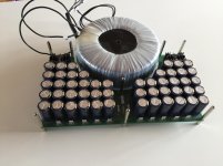
The following board in the attached picture gives 110.000uF/50V or 90.000uF/63V for 230€.
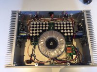
On the second picture you can see a build up using this powersupply and a 800VA transformer.
Cabling is a bit sluggish.
The following board in the attached picture gives 110.000uF/50V or 90.000uF/63V for 230€.
On the second picture you can see a build up using this powersupply and a 800VA transformer.
Cabling is a bit sluggish.
Attachments
MIRAND A1 V12 specs. Updated!!!
I did some optimization on resistor and capacitor values. Now this has enhanced the performance.
Test is done on a 800VA transformer with 2x32VAC secondaries.
Previous slew rate was 200V/uSec. It is now 300V/uSec.
Bandwidth was 800KHz. It is now 1.3MHz.
The power rating is:
80Watt @8Ohm.
150Watt @4Ohm.
250Watt @2Ohm.
We have optimized on all the amps that we will ship out. No one will not get the old performance.
Only one thing that the amp has hard time cooping with is 10 - 15VDC on the inputs.
So if one plays around with frontends and is a bit reckless from time to time like me i would suggest installing a good capacitor on the front where there is place for it. 4,7uF (-3dB at 3Hz)
5 is sold out of 12 sets.
BR
Sonny
It is the first time today that I have checked this thread....
I have some news. For the amplifier, we have designed and ordered a discrete balanced input frontend. It has +6dB gain on top of the 26,9dB gain of the amplifier.
Input impedance is 10Kohm.
Vitalica have ordered them as well. This frontend module cost 80€.
Now AnthonyA: Yes i am working on a Preamp based on the same technology as the Mirand A1 V1.2
More tomorrow.
- Sonny
Just A quick update.
We have made a shield board for the discrete output stage. The board where the gain modules are mounted. We have modified the mute circuit to shunt to GND rather than disabling. And it works better and has less impact on the sound.

Also we still have the phono stage which can run at up to 22V supply giving it more headroom.
For the phonostage we just deliver a variant of our LPS V2.1 with output voltage changed to 22V instead of 15V.
If it is shielded from the power supply it produces a very quiet signal which is neutral sounding and in the same time has the same wonderful sound signature of the gain modules.
It can easily be used for MC pickup as well as MM.


We have made a shield board for the discrete output stage. The board where the gain modules are mounted. We have modified the mute circuit to shunt to GND rather than disabling. And it works better and has less impact on the sound.
Also we still have the phono stage which can run at up to 22V supply giving it more headroom.
For the phonostage we just deliver a variant of our LPS V2.1 with output voltage changed to 22V instead of 15V.
If it is shielded from the power supply it produces a very quiet signal which is neutral sounding and in the same time has the same wonderful sound signature of the gain modules.
It can easily be used for MC pickup as well as MM.
Very interesting!
This new output shield..tempting..
I have noted that the gain modules run quite warm.
With 22V I think the thermal arrangement will become an issue?
Do they change with different ps voltages? I mean the sound.
Then.. there had been a question about the gain modules.
I had compared them to the Five Fish DOA12, class a jfet modules which had been a 'best buy' choice amongst the mivera users group.
Sonny's modules are far better, for us here.
Very interesting!
This new output shield..tempting..
I have noted that the gain modules run quite warm.
With 22V I think the thermal arrangement will become an issue?
Do they change with different ps voltages? I mean the sound.
Then.. there had been a question about the gain modules.
I had compared them to the Five Fish DOA12, class a jfet modules which had been a 'best buy' choice amongst the mivera users group.
Sonny's modules are far better, for us here.
We have adjusted some of the current to get a lower power dissipation. We are aware of it with the higher voltage. It is mainly in the frontend VAS conversion and it is not necessary to run that high bias as we have done.
And thanks Joseph.
I do not know if it makes sense to write this.:
The Mirand A1 V1.2 is not exacly cheap with 199€/channel.
So if someone would ask what if they break? Will they put out DC on the speakers? Short no they will not put out DC on the speakers. Only max a few Volt but that is in faulty state... Normally we should not see more than a dew millivolts.
The protection circuit is a separate section. Meaning that it monitors powersupply and DC on the output. So if they break or the customers have put DC on the input, They will disable the output.
If a customer is not sure about the source or if they are playing around with sources... I would strongly recommend to install a capacitor in the input... There is space for it.....
It can happen to us (Also me) all, if we play with own build (DIY preamps and DAC's) sources, that we could have DC on the input and 2.5 to 3 VDC should not be a problem but 5 - 15VDC will destroy the input on the amp due to excessive current through the input stages. ...
Short i am prepared to support in such cases. And we do repair them...
Just A quick update.
We have made a shield board for the discrete output stage. The board where the gain modules are mounted. We have modified the mute circuit to shunt to GND rather than disabling. And it works better and has less impact on the sound.
Hi Sonny,
Is this a modification that we can do to our existing PCB or it is a complete new PCB design?
Thanks
Do
Hi Sonny,
Is this a modification that we can do to our existing PCB or it is a complete new PCB design?
Thanks
Do
Hi Dominic.
It is a new PCB and it cost 61€ plus shipping. The gain modules fits on top of it.
BR
Sonny
New Gain module and how to modify the previous version
We have a new Gain module on its way. It sounds better and the current is lower and less heat.
Now existing customers can change there modules if they are experienced in SMT assembly.
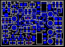
Look at the attached picture.
X = remove, If red line (Q3) then a short.
z = 0R 0603 resistor
Y = 620R 1% 0603 resistor
W = 22pF
The new Gain module cost 80€
First One M owner of destroyed modules will be able to buy a Mirand amplifier that is drop in compatible
Yes we are going to make a drop in replacement for First One M. It is not a copy, and it is based on the Mirand A1 V1.2 technology but not as advanced and good. But still very good. Simply not space for a complete Mirand A1 V1.2 in those dimension.
Key things here:
BR
Sonny
We have a new Gain module on its way. It sounds better and the current is lower and less heat.
Now existing customers can change there modules if they are experienced in SMT assembly.
Look at the attached picture.
X = remove, If red line (Q3) then a short.
z = 0R 0603 resistor
Y = 620R 1% 0603 resistor
W = 22pF
The new Gain module cost 80€
First One M owner of destroyed modules will be able to buy a Mirand amplifier that is drop in compatible
Yes we are going to make a drop in replacement for First One M. It is not a copy, and it is based on the Mirand A1 V1.2 technology but not as advanced and good. But still very good. Simply not space for a complete Mirand A1 V1.2 in those dimension.
Key things here:
- LxW : 100x50mm
- Current feedback all bipolar - No Lateral fets
- DC protection and under voltage lockout
- DC Servo
- 1 trimmer only for bias adjust ... Bias discrete with only BJT and less noisy
- Expected price 150€/channel
BR
Sonny
Attachments


- Home
- Vendor's Bazaar
- AK4490 USB Dac with dsd support.