Sonny - I am seeing a bit of an issue with DSD64 occasionally losing lock. You can see my setup above. I am running the DAC PS at 7V (config. wise, it was easier to hit 7V than 5.25V).
May i ask what you use for playback?
Sent from my iPhone using Tapatalk
Briefly.Bass is good like you and others have said.There is also quite a bit of details.Overall musicality is good.I would love to hear what you think in detail.
I think Sonny will be happy when he reads thisHey Sonny - it's not your DAC/Firmware; it's the OS X beta...
")
Did some more listening tests since I'm preparing to review the DAC, and I can honestly say that for the price, it can't get better than this. This DAC can easily compete with 3K to 5K DACs and probably even more if your setup is properly done. I own two ES9018(16) DACs, one is a TPA BII with NTD1 v.2 I/V and the other which I sold was a Simaudio 380D DSD, and although they had a bit more details, they didn't have the musicality this DAC has. And for many recordings, I prefer the AK4490 (Sonny's implementation) over the ES9018. I'll say more when I'm done with my listening tests but so far this DAC is a little jewel!
Ciao!
Do
Ciao!
Do
Somebody please correct me if I'm wrong..
This DAC is still in the development stage, both hardware and software.. on official site there is still no price, specifications, manual etc.. on this site I also do not find such informations, except price..
Would someone could write basic data in one post, which will not be changed..
This DAC is still in the development stage, both hardware and software.. on official site there is still no price, specifications, manual etc.. on this site I also do not find such informations, except price..
Would someone could write basic data in one post, which will not be changed..
Somebody please correct me if I'm wrong..
This DAC is still in the development stage, both hardware and software.. on official site there is still no price, specifications, manual etc.. on this site I also do not find such informations, except price..
Would someone could write basic data in one post, which will not be changed..
Most of the information is on post #1
Do
Most of the information is on post #1
There is no photos yet..
There is no any specific information about the output stage..
There is no data related to the device in terms of power consumption, output voltage, there is no driver for Windows..
There is no technical instructions for the release device in operation..
Somebody please correct me if I'm wrong..
This DAC is still in the development stage, both hardware and software.. on official site there is still no price, specifications, manual etc.. on this site I also do not find such informations, except price..
Would someone could write basic data in one post, which will not be changed..
The dac is fully developed, but i am Working on extensions for it. It will Work without the extensions, but the extensions will ADD extra features .
For the website. I will get it done today. I admit i have been Working on the extensions rather than updating the website.
Br
Sonny
Sent from my iPhone using Tapatalk
There is no photos yet..
There is no any specific information about the output stage..
There is no data related to the device in terms of power consumption, output voltage, there is no driver for Windows..
There is no technical instructions for the release device in operation..
The datasheets are attached.
The windows driver is on a usb flash stick together with the module.
BR
Sonny
Attachments
Quotes and facts about the Mirand Audio USB dac
Hi all,
First of all I want to say, following Sonny since June 2014, that I am deeply impressed with what he has accomplished. First with the TSSA 1.7 poweramp modules and now the usb dac.
What strikes me - even as a non engineer - is that this dac is NOT 'a fast by the standard datasheet dac' with ordinary PCB and components. Everything is given great thought, the PCB is first class and populated / soldered inhouse at Sonny's own lab using top quality smd components. Even the firmware for the dac and the coming preamp / frontpanel / display is coded / adapted inhouse.
Before deciding to join the early bird / preoder list, I started combing through this thread (and the TSSA 1.7 thread where the usb dac originated) to gather all the quotes / answers from Sony with additional interesting facts / insight into the dac (besides post #1) and the design choices behind the different solutions. Hope you will find this useful as a (noncomplete) summary. (I have not covered the coming output boards, frontpanel, display, filterchoices, etc)
The Kit / dac --- "Kit contains USB DAC mainboard, output shield, single ended, power cable assembly and USB Stick with Windows driver and documents”
Diy AK4490 implemenations --- "The Big difference here is the housekeeping around the dac. It is superior (IMO)to other on my dac.“
The Oscilator / crystal --- "I have been looking on them (NDK NZ2520SD). They are not easy to get, and they are better but cost 4 times more. But a bad PCB layout can make the difference Zero. I have choosen to use the HC736R from foxcon . They are low jitter types, coupled with a good layout they will perform very well”..."the oscillator has its own low noise ldo, also we use Line matching”
The AK4490 chip --- "It runs at 6.1V just below the voltage of the PCK0J152MCO1GS we use for bypass of VREF rails. They are polymer types with 8mOhm ESR value and keeps it very low (<20mOhm) to a few MHz. The capacitor we have choosen for VREF is also 1500uF. So for sure you can gain better S/N ratio (by running it at 7v), but we get a better capacitor by reducing it to 6.1V instead. Also with 1500uF we improve it in the low range. So what do you want? gain 1 - 2dB better S/N ratio or having better overall results?”
The Opamp / SE shield --- “Ada4627-1arz. It is better than most of the opamps out there.”
PCM and DSD out --- "PCM 2.4Vrms, DSD 1.5Vrms (with Volume bypass). DSD is lower as we bypass as much as possible in the DSD mode. (It is not possible to bypass Volume control in PCM in the AK4490).” ... "It (PCM) does not perform worse at all. Gain is set to 0dB meaning the digital attenuator is transparant. I have put a lot of Work into use of good isolation of the voltageregulators that ultra low noise and ultra high psrr"
Powersupply --- "I would always go for higher psrr values. So preregulated power source. But it does not have to be expensive or low noise level here. What you want is to reject as much hum as possible. So use something like lm317/337 In front regulation .... It would give a total psrr of more than 100dB up to 1KHz. The board it self lays around 70dB up to 100KHz. So 200mVpp ripple is ok”
To DIY or not to DIY --- "I have choosen to lock the mainboard.*There is a lot of different voltages here. 1V, 3.3V, 5V, 6.1V, +/-14V, +/-15V and +5.5V So a wrong move experimenting with the mainboard will destroy a lot of parts.*On the Output shield board i encourage all to play around.”
Plus all that I lost track of in these late hours...
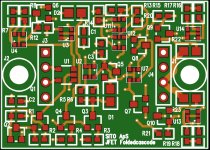
Discrete opamp for new outputshield
We have just ordered the discrete opamp modules for the balanced shield.
The opamp if 35x25mm in size even though the pinout is identical to standard single opamps, the row spacing does not match. Simply .. it draws to much current to replace any opamp. It is drawing 30mA, so i decided not to cramp it down.
Row spacing is 20mm.
Mountinghole spacing is 29mm.
It is an JFET folded cascode design with very low distortion. See it as an AD797 seasoned with jfet's (the salt).
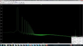
Simulated distortion with 2 x gain is 0.002231% @ 200KHz, 8Vpp, 10kload, feedback resistors 2K,2K.
under same condition 0.000120% @ 10KHz
The opamps them self will cost 50€.
But the shield with 4 x of the opamps will cost 166€
How many active parts? 24 bjt's,4 jfets, 2 leds.
We have just ordered the discrete opamp modules for the balanced shield.
The opamp if 35x25mm in size even though the pinout is identical to standard single opamps, the row spacing does not match. Simply .. it draws to much current to replace any opamp. It is drawing 30mA, so i decided not to cramp it down.
Row spacing is 20mm.
Mountinghole spacing is 29mm.
It is an JFET folded cascode design with very low distortion. See it as an AD797 seasoned with jfet's (the salt).
Simulated distortion with 2 x gain is 0.002231% @ 200KHz, 8Vpp, 10kload, feedback resistors 2K,2K.
under same condition 0.000120% @ 10KHz
The opamps them self will cost 50€.
But the shield with 4 x of the opamps will cost 166€
How many active parts? 24 bjt's,4 jfets, 2 leds.
Attachments
Last edited:
- Home
- Vendor's Bazaar
- AK4490 USB Dac with dsd support.