I would ask Sonny about the TSSA V4 / V8 amps. They have the grunt you need. I remember Sonny mentioning that he had had them stable at 1 ohm (!) delivering considerable amount of power (+400 watts) I actually have two boards of the V2 (a less powerfull version) waiting at Sonny's workshop for me. Here are the links to Sonny's threads (also in the vendor bazaar) about the TSSA 1.7 and the TSSA V4/V8:...As for the amps I'm not sure yet what choice would be good for me. I have Troels SBA10 speakers that go down to 2.85ohm in bass region...
TSSA V1.7 mosfet Current feedback amp module
Mirand TSSA V4 and V8 Lateral mosfet amp
BR, Per
About several threads vs one thread: I actually was for several threads (like TSSA V1.7 mosfet Current feedback amp module and Mirand TSSA V4 and V8 Lateral mosfet amp) but I am not so sure anymore. You loose the overview having more than one thread and things often inter relate - like gain modules. Maybe two threads: This one for DACs, preamps, gain modules, etc and another thread for Poweramps. But keeping one thread and just linking directly to the updated Mirand website (sections) might be best. It would take less time for Sonny (not having to take all the power amp posts out) BTW I saw one poster having updated news (text and links) in his signature, so no one would miss it even if they missed a post All the best, Per
Last edited:
I must admit that coming to the thread with name that clearly points to DAC and not familiar with nomenclatures used I'm pretty confused. What are the DAC parts, what the preamps and what the ampsAnd I can not spend days reading the whole thread 202 pages...
I have just attached the manual for A1 V1.2 manual.
And I have checked if the power supply of 63V is possible and i can supply variant of it with 63V option.
Attachments
Datasheet on the DAC board.
OLED and Preamp will follow shortly.
Sonny,
regarding the dac V1.2a, in order to define the correct panel cut-out for the connectors (usb, spdif, coax), can you provide more details regarding their positions on the pcb ?
In the datasheet you issued there is only a view with board overall dimensions in the X-Y plane (horizontal).
It would be useful to have another one in the X-Z plane (vertical) or at least, in addition to the x-y positioning of connectors, the model /manufacturer of each connector.
Thanks.
Sent me an e-mail to 'mail at Mirand-audio. Dk'I so want to try those A1 V1.2 amplifier modules!!
Mirand A1 V1.2 summary
Hi !
After spending some time on this thread gathering info on the amp module
I'm interested in, I finally gathered most relevant info (to me) in a text file I'm posting here below.
It may save some time and help new comers like myself .........
-------------------------------
VERSION 1.1 (V1.2 next)
-----------------------------------------
#1568
It uses two pairs of MJW3281A/1302A.. They are not super expensive and is available in large
http://www.onsemi.com/pub/Collateral/MJW3281A-D.PDF
50VDC is 120Watt into 8Ohm. It all should give a good low impedance speaker control.
News:
We are starting production of the MIRAND A1 V1.1 as shown on the pictures below.
It is still a reference for what we do of Audio amplifier design.
It uses 1 pair of MJW3281A/1302A. It is rated for no more than 100Watt into 8Ohm and 4Ohm loads. It is stable into 2 ohms load but not for long term uses in 2 Ohms load.
When running as a 50Watt amplifier it can easily drive down to 2 Ohm load.
It is a single ended input Current feedback design. There is only 1 trimmer for BIAS adjustment.
Technology: Current feedback with superbuffer output stage.
Input : SE 10KOhm.
Output mode: Class A or Class AB depending on bias adjustment, heatsinks and Powersupply voltage.
Power supply: +/-30VDC to +/-50VDC
Bandwidth : 1Hz to 800KHz.
Slewrate : 80V/usec.
Peak current +/-15APeak
Protection : Mute circuit and DC protection
PCB Size: 80x120mm
Connectors: Faston 6.3mm
optional input AC coupling capacitor (Mundorf)
We deliver them with output transistors mounted in horizontal or vertical installation.
The only thing needed more is to add a power supply and mechanical assembly.
First boards are scheduled to arrive 20.07.18
------------------------------
The Mirand A1 V1.2 is ready.
It is a 4 layer board and this amp is very good sounding and extremely quiet.
What we have done is that we have changed the Size to 120x80mm.
This have made it possible to add the DC and UnderVoltage protection to the amp.
We use Mosfet's with an on resistance of total 7.8mOhm making it possible to use them without heatsinks.
Secondly we have taken the Voltage regulators from the LPS V2.1 to make the +/-15V on the board..
The power supply i would suggest a minimum 300VA 2x24VAC and 2x22000uF
60.000uF and 500 - 600VA 2x32VAC or higher capacitor for an 100Watt amplifier.
It runs from +/-30VDC (1A max idle) to +/-50VDC (max 0.5A idle).. Idle is only suggestions but always take into account the heatsink cooling efficiency.
It can run stable at 100mA if you want to. That is 6 - 10Watt per channel in idle power.
Many options here.
I have attached a screenshot.
So key data:
Size : 120x80x40mm (LxWxH)
+/-30 to 50VDC
50 - 100Watt @ 8 Ohm.
2 Ohm Stable
Bandwidth : 800KHz
Only adjustment is bias current, DC servo integrated
DC and UV protection
Current feedback
SE input : 10KOhm
__________________________________
#1579
MIRAND A1 V12 specs.
I have attached scope shots.
Measured slew rate is 200V/uSec.
Bandwidth 800KHz.
Distortion at +/-31V and 40Watt into 8 Ohm. <0.01%
Distortion at +/-31V and 80Watt into 4 Ohm. <0.01%
Bias during test : 35mA
total current consumption :100mA
Power disipation : 6,2Watt at +/-31VDC.
DC protection is tested and starts to kick in below 5 Hz. Above it does not limit.
Undervoltage lockout is below +/-21VDC
--------------------------------------
#1585
MIRAND A1 V12 specs. Updated!!!
I did some optimization on resistor and capacitor values. Now this has enhanced the performance.
Test is done on a 800VA transformer with 2x32VAC secondaries.
Previous slew rate was 200V/uSec. It is now 300V/uSec.
Bandwidth was 800KHz. It is now 1.3MHz.
The power rating is:
80Watt @8Ohm.
150Watt @4Ohm.
250Watt @2Ohm.
_______________________________________
#1589
It is the first time today that I have checked this thread....
I have some news. For the amplifier, we have designed and ordered a discrete balanced input frontend. It has +6dB gain on top of the 26,9dB gain of the amplifier.
Input impedance is 10Kohm.
Vitalica have ordered them as well. This frontend module cost 80€.
Now AnthonyA: Yes i am working on a Preamp based on the same technology as the Mirand A1 V1.2
More tomorrow.
----------------------------------------------------
#1593
Ridicules ... Mirand A1 V1.2 .... i have set the gain to 11x instead of 21x by an accident....
And they slew with up to 450V/uSec... No issue with oscillation.
--------------------------------------------------------
#1594
I do not know if it makes sense to write this.:
The Mirand A1 V1.2 is not exacly cheap with 199€/channel.
So if someone would ask what if they break? Will they put out DC on the speakers? Short no they will not put out DC on the speakers. Only max a few Volt but that is in faulty state... Normally we should not see more than a dew millivolts.
The protection circuit is a separate section. Meaning that it monitors powersupply and DC on the output. So if they break or the customers have put DC on the input, They will disable the output.
If a customer is not sure about the source or if they are playing around with sources... I would strongly recommend to install a capacitor in the input... There is space for it.....
It can happen to us (Also me) all, if we play with own build (DIY preamps and DAC's) sources, that we could have DC on the input and 2.5 to 3 VDC should not be a problem but 5 - 15VDC will destroy the input on the amp due to excessive current through the input stages. ...
Short i am prepared to support in such cases. And we do repair them...
----------------------------------------------------------
#1615
Mirand A1 V1.2 description
Supernet has got the same info but:
I am Making a Manual that will be released later today.
The basic information right now is:
It is a Current feedback design, that I have been working for years and slowly have been updated on several point.
One thing that I value very high is that the idle current in every stage is stable. So a basic design gets a bit complicated because of my goal. It means for example that my VAS stage has fixed current of around 4mA, this in return gives a fixed impedance of the VAS stage. Again during heat up we have a stable openloop gain so that the amplifier has nearly the same sound signature from cold to warm state. Only part that drifts very slowly is the bias current of the output stage but that is due to heat up of the output devices from cold to warm state. This in return makes it very easy to set the Bias because we do not have a fluctation in VAS stage.
Some of the issues that can be a pain in DC coupled Current feedback is that we have a fluctation on the DC offset. Not much if done right but we have choosen to add a DC Servo because if the Source puts out DC it will get multiplied by the gain of the amplifier.
DC offset is monitored as well as supply voltage. We have an under voltage detect that trips below +/-21V.
DC offset + startup + under voltage lockout disables the SSR relay in the output. Which has a ON resistance of 8mOhm.
Only trimming necessary is Bias current.
The specs are:
Board size : 71x110mm
All bipolar design.
Minimum current consumption : 50mA
Minimum bias current : 25mA
Supply voltage : +/-24VDC to +/-50VDC
Slewrate : 300V/uSec
Bandwidth : 1.2MHz
Power rating at +/-46VDC : 80W@8R, 150W@4R, 250W@2R
------------------------------------------------------------
#1629
MIRAND A1 V1.2 dimension drawing
I have attached the dimension drawing. Installation guide is in the working.
It is very easy to work with.
Tools needed for installation:
[*] 2.5mm drill for 3mm screws[*] 3mm std tap for aluminium.[*] The spacer will with 1mm countersunk because the last 1mm on the spacers have no thread.
A video of tapping from Bosch:
YouTube
Attached Files
File Type: pdf MIRAND A1 V12 dimensions.pdf (29.7 KB, 34 views)
---------------------------------------------------------------------
#1682
MIRAND A1 V12 THD
Attached is a waveform i just did of the Mirand A1 V12 for 27W into 8R.
Have a good evening everyone.
Attached Files
File Type: pdf mirand a1 v12 27W 1khz 8R.pdf (548.7 KB, 60 views)
-----------------------------------------------------------------
#1684
More MIRAND A1 V1.2 Measurement.
They are done with 25mA bias. 10mV across the measurement points.
Attached Files
File Type: pdf mirand a1 v12 4vrms 1khz no load - 3 25mA bias.pdf (326.5 KB, 12 views)
File Type: pdf mirand a1 v12 8vrms 1khz 8R - 3 25mA bias.pdf (432.1 KB, 10 views)
File Type: pdf mirand a1 v12 8vrms 1khz no load.pdf (430.6 KB, 12 views)
File Type: pdf mirand a1 v12 27W 1khz 8R - 2 25mA bias.pdf (379.2 KB, 12 views)
File Type: pdf mirand a1 v12 4vrms 1khz 8R - 3 25mA bias.pdf (375.4 KB, 11 views)
-----------------------------------------------------------------------------
#1685
MIRAND A1 V1.2 Manual
We have attached a Dropbox link to the MIRAND A1 V1.2 Manual:
Dropbox - Mirand A1 V12 Manual.pdf
----------------------------------------------------------------------
#1808
Hello,
I've been helping my friend cOz with adjusting the amp (by chat only), bias and offset. But he ended up measuring quite different offset on L R channels.
I am a bit more experienced but still not exactly an expert, and not having a schematic I thought, better ask.
However trim procedure seems easy in steps it's a bit confusing when you compare parts of the manual so I have put them in one place in picture.
Please comment the picture
Attached Thumbnails
AK4490 USB Dac with dsd support.-amp-adjust-jpg
------------------------------------------------------
#2023
Quote:
Originally Posted by Bassivus View Post
I must admit that coming to the thread with name that clearly points to DAC and not familiar with nomenclatures used I'm pretty confused. What are the DAC parts, what the preamps and what the amps And I can not spend days reading the whole thread 202 pages...
I have just attached the manual for A1 V1.2 manual.
And I have checked if the power supply of 63V is possible and i can supply variant of it with 63V option.
Attached Thumbnails
AK4490 USB Dac with dsd support.-mirand-a1-v12-jpg
Attached Files
File Type: pdf Mirand A1 V12 Manual 130619.pdf (971.1 KB, 20 views)
-------------------------------------------------------
Hi !
After spending some time on this thread gathering info on the amp module
I'm interested in, I finally gathered most relevant info (to me) in a text file I'm posting here below.
It may save some time and help new comers like myself .........
-------------------------------
VERSION 1.1 (V1.2 next)
-----------------------------------------
#1568
It uses two pairs of MJW3281A/1302A.. They are not super expensive and is available in large
http://www.onsemi.com/pub/Collateral/MJW3281A-D.PDF
50VDC is 120Watt into 8Ohm. It all should give a good low impedance speaker control.
News:
We are starting production of the MIRAND A1 V1.1 as shown on the pictures below.
It is still a reference for what we do of Audio amplifier design.
It uses 1 pair of MJW3281A/1302A. It is rated for no more than 100Watt into 8Ohm and 4Ohm loads. It is stable into 2 ohms load but not for long term uses in 2 Ohms load.
When running as a 50Watt amplifier it can easily drive down to 2 Ohm load.
It is a single ended input Current feedback design. There is only 1 trimmer for BIAS adjustment.
Technology: Current feedback with superbuffer output stage.
Input : SE 10KOhm.
Output mode: Class A or Class AB depending on bias adjustment, heatsinks and Powersupply voltage.
Power supply: +/-30VDC to +/-50VDC
Bandwidth : 1Hz to 800KHz.
Slewrate : 80V/usec.
Peak current +/-15APeak
Protection : Mute circuit and DC protection
PCB Size: 80x120mm
Connectors: Faston 6.3mm
optional input AC coupling capacitor (Mundorf)
We deliver them with output transistors mounted in horizontal or vertical installation.
The only thing needed more is to add a power supply and mechanical assembly.
First boards are scheduled to arrive 20.07.18
------------------------------
The Mirand A1 V1.2 is ready.
It is a 4 layer board and this amp is very good sounding and extremely quiet.
What we have done is that we have changed the Size to 120x80mm.
This have made it possible to add the DC and UnderVoltage protection to the amp.
We use Mosfet's with an on resistance of total 7.8mOhm making it possible to use them without heatsinks.
Secondly we have taken the Voltage regulators from the LPS V2.1 to make the +/-15V on the board..
The power supply i would suggest a minimum 300VA 2x24VAC and 2x22000uF
60.000uF and 500 - 600VA 2x32VAC or higher capacitor for an 100Watt amplifier.
It runs from +/-30VDC (1A max idle) to +/-50VDC (max 0.5A idle).. Idle is only suggestions but always take into account the heatsink cooling efficiency.
It can run stable at 100mA if you want to. That is 6 - 10Watt per channel in idle power.
Many options here.
I have attached a screenshot.
So key data:
Size : 120x80x40mm (LxWxH)
+/-30 to 50VDC
50 - 100Watt @ 8 Ohm.
2 Ohm Stable
Bandwidth : 800KHz
Only adjustment is bias current, DC servo integrated
DC and UV protection
Current feedback
SE input : 10KOhm
__________________________________
#1579
MIRAND A1 V12 specs.
I have attached scope shots.
Measured slew rate is 200V/uSec.
Bandwidth 800KHz.
Distortion at +/-31V and 40Watt into 8 Ohm. <0.01%
Distortion at +/-31V and 80Watt into 4 Ohm. <0.01%
Bias during test : 35mA
total current consumption :100mA
Power disipation : 6,2Watt at +/-31VDC.
DC protection is tested and starts to kick in below 5 Hz. Above it does not limit.
Undervoltage lockout is below +/-21VDC
--------------------------------------
#1585
MIRAND A1 V12 specs. Updated!!!
I did some optimization on resistor and capacitor values. Now this has enhanced the performance.
Test is done on a 800VA transformer with 2x32VAC secondaries.
Previous slew rate was 200V/uSec. It is now 300V/uSec.
Bandwidth was 800KHz. It is now 1.3MHz.
The power rating is:
80Watt @8Ohm.
150Watt @4Ohm.
250Watt @2Ohm.
_______________________________________
#1589
It is the first time today that I have checked this thread....
I have some news. For the amplifier, we have designed and ordered a discrete balanced input frontend. It has +6dB gain on top of the 26,9dB gain of the amplifier.
Input impedance is 10Kohm.
Vitalica have ordered them as well. This frontend module cost 80€.
Now AnthonyA: Yes i am working on a Preamp based on the same technology as the Mirand A1 V1.2
More tomorrow.
----------------------------------------------------
#1593
Ridicules ... Mirand A1 V1.2 .... i have set the gain to 11x instead of 21x by an accident....
And they slew with up to 450V/uSec... No issue with oscillation.
--------------------------------------------------------
#1594
I do not know if it makes sense to write this.:
The Mirand A1 V1.2 is not exacly cheap with 199€/channel.
So if someone would ask what if they break? Will they put out DC on the speakers? Short no they will not put out DC on the speakers. Only max a few Volt but that is in faulty state... Normally we should not see more than a dew millivolts.
The protection circuit is a separate section. Meaning that it monitors powersupply and DC on the output. So if they break or the customers have put DC on the input, They will disable the output.
If a customer is not sure about the source or if they are playing around with sources... I would strongly recommend to install a capacitor in the input... There is space for it.....
It can happen to us (Also me) all, if we play with own build (DIY preamps and DAC's) sources, that we could have DC on the input and 2.5 to 3 VDC should not be a problem but 5 - 15VDC will destroy the input on the amp due to excessive current through the input stages. ...
Short i am prepared to support in such cases. And we do repair them...
----------------------------------------------------------
#1615
Mirand A1 V1.2 description
Supernet has got the same info but:
I am Making a Manual that will be released later today.
The basic information right now is:
It is a Current feedback design, that I have been working for years and slowly have been updated on several point.
One thing that I value very high is that the idle current in every stage is stable. So a basic design gets a bit complicated because of my goal. It means for example that my VAS stage has fixed current of around 4mA, this in return gives a fixed impedance of the VAS stage. Again during heat up we have a stable openloop gain so that the amplifier has nearly the same sound signature from cold to warm state. Only part that drifts very slowly is the bias current of the output stage but that is due to heat up of the output devices from cold to warm state. This in return makes it very easy to set the Bias because we do not have a fluctation in VAS stage.
Some of the issues that can be a pain in DC coupled Current feedback is that we have a fluctation on the DC offset. Not much if done right but we have choosen to add a DC Servo because if the Source puts out DC it will get multiplied by the gain of the amplifier.
DC offset is monitored as well as supply voltage. We have an under voltage detect that trips below +/-21V.
DC offset + startup + under voltage lockout disables the SSR relay in the output. Which has a ON resistance of 8mOhm.
Only trimming necessary is Bias current.
The specs are:
Board size : 71x110mm
All bipolar design.
Minimum current consumption : 50mA
Minimum bias current : 25mA
Supply voltage : +/-24VDC to +/-50VDC
Slewrate : 300V/uSec
Bandwidth : 1.2MHz
Power rating at +/-46VDC : 80W@8R, 150W@4R, 250W@2R
------------------------------------------------------------
#1629
MIRAND A1 V1.2 dimension drawing
I have attached the dimension drawing. Installation guide is in the working.
It is very easy to work with.
Tools needed for installation:
[*] 2.5mm drill for 3mm screws[*] 3mm std tap for aluminium.[*] The spacer will with 1mm countersunk because the last 1mm on the spacers have no thread.
A video of tapping from Bosch:
YouTube
Attached Files
File Type: pdf MIRAND A1 V12 dimensions.pdf (29.7 KB, 34 views)
---------------------------------------------------------------------
#1682
MIRAND A1 V12 THD
Attached is a waveform i just did of the Mirand A1 V12 for 27W into 8R.
Have a good evening everyone.
Attached Files
File Type: pdf mirand a1 v12 27W 1khz 8R.pdf (548.7 KB, 60 views)
-----------------------------------------------------------------
#1684
More MIRAND A1 V1.2 Measurement.
They are done with 25mA bias. 10mV across the measurement points.
Attached Files
File Type: pdf mirand a1 v12 4vrms 1khz no load - 3 25mA bias.pdf (326.5 KB, 12 views)
File Type: pdf mirand a1 v12 8vrms 1khz 8R - 3 25mA bias.pdf (432.1 KB, 10 views)
File Type: pdf mirand a1 v12 8vrms 1khz no load.pdf (430.6 KB, 12 views)
File Type: pdf mirand a1 v12 27W 1khz 8R - 2 25mA bias.pdf (379.2 KB, 12 views)
File Type: pdf mirand a1 v12 4vrms 1khz 8R - 3 25mA bias.pdf (375.4 KB, 11 views)
-----------------------------------------------------------------------------
#1685
MIRAND A1 V1.2 Manual
We have attached a Dropbox link to the MIRAND A1 V1.2 Manual:
Dropbox - Mirand A1 V12 Manual.pdf
----------------------------------------------------------------------
#1808
Hello,
I've been helping my friend cOz with adjusting the amp (by chat only), bias and offset. But he ended up measuring quite different offset on L R channels.
I am a bit more experienced but still not exactly an expert, and not having a schematic I thought, better ask.
However trim procedure seems easy in steps it's a bit confusing when you compare parts of the manual so I have put them in one place in picture.
Please comment the picture
Attached Thumbnails
AK4490 USB Dac with dsd support.-amp-adjust-jpg
------------------------------------------------------
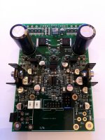
#2023
Quote:
Originally Posted by Bassivus View Post
I must admit that coming to the thread with name that clearly points to DAC and not familiar with nomenclatures used I'm pretty confused. What are the DAC parts, what the preamps and what the amps And I can not spend days reading the whole thread 202 pages...
I have just attached the manual for A1 V1.2 manual.
And I have checked if the power supply of 63V is possible and i can supply variant of it with 63V option.
Attached Thumbnails
AK4490 USB Dac with dsd support.-mirand-a1-v12-jpg
Attached Files
File Type: pdf Mirand A1 V12 Manual 130619.pdf (971.1 KB, 20 views)
-------------------------------------------------------
I would like to address the talk about using Mosfet. To turn on and off mosfet. You need to overcome the gate charge. The larger the mosfet is the larger the gate charge.
So your drive circuit needs to be handle the high current needed to charge/discharge the gate. Also discharging gate is slower than charging the gate meaning switch off is slow and you will get shoot-through.
High gate charge combined with trace inductance and low series resistance makes a series LCR circuit that very easily can oscillate destroying mosfet or gate drivers.
To overcome the issue with slow turn off/on mosfet based amplifiers are running at high idle so that you don't hear the cross over distortion.
That is why i have not done more lateral mosfet designs.
- Sonny
Hi !
After spending some time on this thread gathering info on the amp module
I'm interested in, I finally gathered most relevant info (to me) in a text file I'm posting here below.
It may save some time and help new comers like myself .........
-------------------------------
VERSION 1.1 (V1.2 next)
-----------------------------------------
#1568
It uses two pairs of MJW3281A/1302A.. They are not super expensive and is available in large
http://www.onsemi.com/pub/Collateral/MJW3281A-D.PDF
50VDC is 120Watt into 8Ohm. It all should give a good low impedance speaker control.
News:
We are starting production of the MIRAND A1 V1.1 as shown on the pictures below.
It is still a reference for what we do of Audio amplifier design.
It uses 1 pair of MJW3281A/1302A. It is rated for no more than 100Watt into 8Ohm and 4Ohm loads. It is stable into 2 ohms load but not for long term uses in 2 Ohms load.
When running as a 50Watt amplifier it can easily drive down to 2 Ohm load.
It is a single ended input Current feedback design. There is only 1 trimmer for BIAS adjustment.
Technology: Current feedback with superbuffer output stage.
Input : SE 10KOhm.
Output mode: Class A or Class AB depending on bias adjustment, heatsinks and Powersupply voltage.
Power supply: +/-30VDC to +/-50VDC
Bandwidth : 1Hz to 800KHz.
Slewrate : 80V/usec.
Peak current +/-15APeak
Protection : Mute circuit and DC protection
PCB Size: 80x120mm
Connectors: Faston 6.3mm
optional input AC coupling capacitor (Mundorf)
We deliver them with output transistors mounted in horizontal or vertical installation.
The only thing needed more is to add a power supply and mechanical assembly.
First boards are scheduled to arrive 20.07.18
------------------------------
The Mirand A1 V1.2 is ready.
It is a 4 layer board and this amp is very good sounding and extremely quiet.
What we have done is that we have changed the Size to 120x80mm.
This have made it possible to add the DC and UnderVoltage protection to the amp.
We use Mosfet's with an on resistance of total 7.8mOhm making it possible to use them without heatsinks.
Secondly we have taken the Voltage regulators from the LPS V2.1 to make the +/-15V on the board..
The power supply i would suggest a minimum 300VA 2x24VAC and 2x22000uF
60.000uF and 500 - 600VA 2x32VAC or higher capacitor for an 100Watt amplifier.
It runs from +/-30VDC (1A max idle) to +/-50VDC (max 0.5A idle).. Idle is only suggestions but always take into account the heatsink cooling efficiency.
It can run stable at 100mA if you want to. That is 6 - 10Watt per channel in idle power.
Many options here.
I have attached a screenshot.
So key data:
Size : 120x80x40mm (LxWxH)
+/-30 to 50VDC
50 - 100Watt @ 8 Ohm.
2 Ohm Stable
Bandwidth : 800KHz
Only adjustment is bias current, DC servo integrated
DC and UV protection
Current feedback
SE input : 10KOhm
__________________________________
#1579
MIRAND A1 V12 specs.
I have attached scope shots.
Measured slew rate is 200V/uSec.
Bandwidth 800KHz.
Distortion at +/-31V and 40Watt into 8 Ohm. <0.01%
Distortion at +/-31V and 80Watt into 4 Ohm. <0.01%
Bias during test : 35mA
total current consumption :100mA
Power disipation : 6,2Watt at +/-31VDC.
DC protection is tested and starts to kick in below 5 Hz. Above it does not limit.
Undervoltage lockout is below +/-21VDC
--------------------------------------
#1585
MIRAND A1 V12 specs. Updated!!!
I did some optimization on resistor and capacitor values. Now this has enhanced the performance.
Test is done on a 800VA transformer with 2x32VAC secondaries.
Previous slew rate was 200V/uSec. It is now 300V/uSec.
Bandwidth was 800KHz. It is now 1.3MHz.
The power rating is:
80Watt @8Ohm.
150Watt @4Ohm.
250Watt @2Ohm.
_______________________________________
#1589
It is the first time today that I have checked this thread....
I have some news. For the amplifier, we have designed and ordered a discrete balanced input frontend. It has +6dB gain on top of the 26,9dB gain of the amplifier.
Input impedance is 10Kohm.
Vitalica have ordered them as well. This frontend module cost 80€.
Now AnthonyA: Yes i am working on a Preamp based on the same technology as the Mirand A1 V1.2
More tomorrow.
----------------------------------------------------
#1593
Ridicules ... Mirand A1 V1.2 .... i have set the gain to 11x instead of 21x by an accident....
And they slew with up to 450V/uSec... No issue with oscillation.
--------------------------------------------------------
#1594
I do not know if it makes sense to write this.:
The Mirand A1 V1.2 is not exacly cheap with 199€/channel.
So if someone would ask what if they break? Will they put out DC on the speakers? Short no they will not put out DC on the speakers. Only max a few Volt but that is in faulty state... Normally we should not see more than a dew millivolts.
The protection circuit is a separate section. Meaning that it monitors powersupply and DC on the output. So if they break or the customers have put DC on the input, They will disable the output.
If a customer is not sure about the source or if they are playing around with sources... I would strongly recommend to install a capacitor in the input... There is space for it.....
It can happen to us (Also me) all, if we play with own build (DIY preamps and DAC's) sources, that we could have DC on the input and 2.5 to 3 VDC should not be a problem but 5 - 15VDC will destroy the input on the amp due to excessive current through the input stages. ...
Short i am prepared to support in such cases. And we do repair them...
----------------------------------------------------------
#1615
Mirand A1 V1.2 description
Supernet has got the same info but:
I am Making a Manual that will be released later today.
The basic information right now is:
It is a Current feedback design, that I have been working for years and slowly have been updated on several point.
One thing that I value very high is that the idle current in every stage is stable. So a basic design gets a bit complicated because of my goal. It means for example that my VAS stage has fixed current of around 4mA, this in return gives a fixed impedance of the VAS stage. Again during heat up we have a stable openloop gain so that the amplifier has nearly the same sound signature from cold to warm state. Only part that drifts very slowly is the bias current of the output stage but that is due to heat up of the output devices from cold to warm state. This in return makes it very easy to set the Bias because we do not have a fluctation in VAS stage.
Some of the issues that can be a pain in DC coupled Current feedback is that we have a fluctation on the DC offset. Not much if done right but we have choosen to add a DC Servo because if the Source puts out DC it will get multiplied by the gain of the amplifier.
DC offset is monitored as well as supply voltage. We have an under voltage detect that trips below +/-21V.
DC offset + startup + under voltage lockout disables the SSR relay in the output. Which has a ON resistance of 8mOhm.
Only trimming necessary is Bias current.
The specs are:
Board size : 71x110mm
All bipolar design.
Minimum current consumption : 50mA
Minimum bias current : 25mA
Supply voltage : +/-24VDC to +/-50VDC
Slewrate : 300V/uSec
Bandwidth : 1.2MHz
Power rating at +/-46VDC : 80W@8R, 150W@4R, 250W@2R
------------------------------------------------------------
#1629
MIRAND A1 V1.2 dimension drawing
I have attached the dimension drawing. Installation guide is in the working.
It is very easy to work with.
Tools needed for installation:
[*] 2.5mm drill for 3mm screws[*] 3mm std tap for aluminium.[*] The spacer will with 1mm countersunk because the last 1mm on the spacers have no thread.
A video of tapping from Bosch:
YouTube
Attached Files
File Type: pdf MIRAND A1 V12 dimensions.pdf (29.7 KB, 34 views)
---------------------------------------------------------------------
#1682
MIRAND A1 V12 THD
Attached is a waveform i just did of the Mirand A1 V12 for 27W into 8R.
Have a good evening everyone.
Attached Files
File Type: pdf mirand a1 v12 27W 1khz 8R.pdf (548.7 KB, 60 views)
-----------------------------------------------------------------
#1684
More MIRAND A1 V1.2 Measurement.
They are done with 25mA bias. 10mV across the measurement points.
Attached Files
File Type: pdf mirand a1 v12 4vrms 1khz no load - 3 25mA bias.pdf (326.5 KB, 12 views)
File Type: pdf mirand a1 v12 8vrms 1khz 8R - 3 25mA bias.pdf (432.1 KB, 10 views)
File Type: pdf mirand a1 v12 8vrms 1khz no load.pdf (430.6 KB, 12 views)
File Type: pdf mirand a1 v12 27W 1khz 8R - 2 25mA bias.pdf (379.2 KB, 12 views)
File Type: pdf mirand a1 v12 4vrms 1khz 8R - 3 25mA bias.pdf (375.4 KB, 11 views)
-----------------------------------------------------------------------------
#1685
MIRAND A1 V1.2 Manual
We have attached a Dropbox link to the MIRAND A1 V1.2 Manual:
Dropbox - Mirand A1 V12 Manual.pdf
----------------------------------------------------------------------
#1808
Hello,
I've been helping my friend cOz with adjusting the amp (by chat only), bias and offset. But he ended up measuring quite different offset on L R channels.
I am a bit more experienced but still not exactly an expert, and not having a schematic I thought, better ask.
However trim procedure seems easy in steps it's a bit confusing when you compare parts of the manual so I have put them in one place in picture.
Please comment the picture
Attached Thumbnails
AK4490 USB Dac with dsd support.-amp-adjust-jpg
------------------------------------------------------
#2023
Quote:
Originally Posted by Bassivus View Post
I must admit that coming to the thread with name that clearly points to DAC and not familiar with nomenclatures used I'm pretty confused. What are the DAC parts, what the preamps and what the amps And I can not spend days reading the whole thread 202 pages...
I have just attached the manual for A1 V1.2 manual.
And I have checked if the power supply of 63V is possible and i can supply variant of it with 63V option.
Attached Thumbnails
AK4490 USB Dac with dsd support.-mirand-a1-v12-jpg
Attached Files
File Type: pdf Mirand A1 V12 Manual 130619.pdf (971.1 KB, 20 views)
-------------------------------------------------------
Wonderful summary. Thanks!
Dear Sonny,
I have to thank you very much for all your work!
To experience that you try everything to hold your pledge is really a joy.
Finally i‘ve got all the promised goods and i just can say „good things need a while“.
Your dac board with the discrete output shield sounds absolutely amazing!
I have a lot of experiences with dac from audio note to weiss engineering and „developed“ many selfmade dac - most with TDA1541 chip...
This nos dac sound very natural, but they often lack in attack and precision. The S4 dac from audial was my favorite and it was even better than my weiss DAC202 for my taste.
Most of the modern dac are maybe impressive and sound attractive in the first moment, but if you listen to them for long, they fail completely in my opinion.
To say it in one phrase: The mirand dac will replace my S4 for sure!
The bass is extremely well controlled and has a lot of contour.
Also the mids are very detailed and smooth and the highs don‘t fail at all - very fast and accurate transients, totally open and transparent.
My ocellia calliope .30 are definitely not forgiving speakers, but the dac sounds really great in every aspect!
Thank you Sonny for all this joy!
Best regards,
Joel


More than neat... I got also pcb today. Including preamp board.


Congratulations, Sonny. Impressive short time from idea to productMIRAND PREAMP SE PPAMP V1. 1 TESTED AND READY TO SHIP WITH OLED DISPLAY PANEL.... [emoji16][emoji817] View attachment 763821
PS: Does 100 mean product no. one hundred from your hand?
Last edited:
Congratulations, Sonny. Impressive short time from idea to product
Quite impressive indeed!

- Home
- Vendor's Bazaar
- AK4490 USB Dac with dsd support.