Any news about when the DAC will be available ?
Best regards
Arthur.
Not really, the limiting factor is availability of the precision resistors, when ordering I was promised 8-10 weeks leadtime, actual leadtime is currently at 13 weeks for one part, and I can't start production until I have all parts.... And it's not like I can find stock somewhere in the quantities needed....
welcome to logistics... bummer!Not really, the limiting factor is availability of the precision resistors, when ordering I was promised 8-10 weeks leadtime, actual leadtime is currently at 13 weeks for one part, and I can't start production until I have all parts.... And it's not like I can find stock somewhere in the quantities needed....
Actually I had a gut-feeling. So enjoy October
")
Hope the DAC will be in time for "Sint Nicolaas" in december.
Tell me how to get this DAC?
In the maximum configuration.
Pretty much all the information is in the first post. PM the OP, and/or wait till he gets the boards on a web store.
The rest of the thread is discussion, and question/answer.
Hi guys, I'm sorry if this is off-topic, there just seems to be some PCM1704 skill on this thread.
I've got a PCM1704 design with OPA627 IVC. Homebrew 8x oversampler is 100% configurable. Actually based on the same FPGA as shown in the initial post.
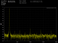
When I'm playing a sine I see quite a bit of harmonics. Is this to be expected?
I get similar harmonics with correlated (2205Hz / 44.1) and uncorrelated (2003Hz / 44.1) sines. The source is a Windows ASIO 24-bit signal generator program. The oversampler is a windowed sinc.
I don't think it's the IVC. Because it's possible to eliminate the 2nd harmonic by setting the oversampler to unit-sample, flat-top (001111111100) and the generator to square output. Hence the DAC's toggling between only two output levels. This test signal obviously has a lot of odd harmonics, but I see very little even harmonics with it.
What I do see, however, is that the capacitor at pin 17 (servo DC) has a lot to say. Initially, I used 560uF OS-CONs on pins 12, 17 and 19. What I'm seeing is that pretty much any other capacitor on pin 17 performs 7-ish dB better in terms of 2nd and 3rd order harmonics while testing with sine waves.
At the moment I'm testing Silmic electrolytes, plastic films and even C0G ceramics.
When I measure on a QuantAsylum QA400, what I see is that the type of capacitors on pins 12 and 19 have very little say. As long as there is anything capacitive there (tested down to 10nF), the noise floor goes down. It's only with these pins floating that I see added noise.
Anybody else here who has explored PCM1704 harmonics in detail?
Best,
Børge
I've got a PCM1704 design with OPA627 IVC. Homebrew 8x oversampler is 100% configurable. Actually based on the same FPGA as shown in the initial post.
When I'm playing a sine I see quite a bit of harmonics. Is this to be expected?
I get similar harmonics with correlated (2205Hz / 44.1) and uncorrelated (2003Hz / 44.1) sines. The source is a Windows ASIO 24-bit signal generator program. The oversampler is a windowed sinc.
I don't think it's the IVC. Because it's possible to eliminate the 2nd harmonic by setting the oversampler to unit-sample, flat-top (001111111100) and the generator to square output. Hence the DAC's toggling between only two output levels. This test signal obviously has a lot of odd harmonics, but I see very little even harmonics with it.
What I do see, however, is that the capacitor at pin 17 (servo DC) has a lot to say. Initially, I used 560uF OS-CONs on pins 12, 17 and 19. What I'm seeing is that pretty much any other capacitor on pin 17 performs 7-ish dB better in terms of 2nd and 3rd order harmonics while testing with sine waves.
At the moment I'm testing Silmic electrolytes, plastic films and even C0G ceramics.
When I measure on a QuantAsylum QA400, what I see is that the type of capacitors on pins 12 and 19 have very little say. As long as there is anything capacitive there (tested down to 10nF), the noise floor goes down. It's only with these pins floating that I see added noise.
Anybody else here who has explored PCM1704 harmonics in detail?
Best,
Børge
Attachments
Børge, it is indeed off topic... miles off-topic. I'd suggest you start your own thread..Hi guys, I'm sorry if this is off-topic, there just seems to be some PCM1704 skill on this thread.
....
Best,
Børge
Actually I would love competent input on the digital filters, seems to be plenty opinions around whats best, from no oversampling/filters, to very long FIR filters, or to FIR filters. Preferable supported by objective test or papers....
x2, IIR sounds much more analog.
An inverse attack and decay gives the illusion of more detail, it's tiring to listen to FIR for over 10 years, the human mind is just so adjusted to it that we keep deleting the inverse, so we must drink more sugar because the FIR filtering requires this mental energy, to listen, maybe around 100kcal per day.
Should have options to choose. Minimum-phase type is preferred, agree completely with John Atkinson.
FIR can do minimum-phase filtering too.
I have included them in the last version of rePhase: http://www.diyaudio.com/forums/mult...hase-linearization-eq-fir-filtering-tool.html
So you can build ultra steep minimum phase filters if you have got enough taps...
As a side note regarding antialiasing filters in rephase, it might not be apparent at first but the samling frequency entry be changed to any arbitrary value, so that beside the usual suspects in the drop menu (44.1k, 48k, etc.) you can also manually enter any value you need.
Søren, many thanks for your ongoing efforts with this development, which I continue to look forward to you bringing to fruition. I'm sure you are finding the part supply delay frustrating but I hope you aren't feeling any pressure from the community - what will be will be.
Anyway, stepping away from the DAC board availability to a more general perspective, I'm just wondering...
Ray
Anyway, stepping away from the DAC board availability to a more general perspective, I'm just wondering...
...have you managed to listen to the prototype?
...did you get any response to your request for help with developing the filters (sadly I cannot offer any skill or experience myself)?
Cheers...did you get any response to your request for help with developing the filters (sadly I cannot offer any skill or experience myself)?
Ray
With a regular R-2R DAC you have the MSB switching at zero crossing, even with t.ex. a -60db signal. That mean that the THD is absolute so if you have -90 db THD at 0 db signal then you have -30 db THD relative to a -60 db signal.
That's why a regular R-2R DAC need to be very precise.
With a Sign Magnitude DAC it's like a sliding window as the MSB are NOT switching with lower level signals, so if you have -90 db THD at 0 db you will still have -90 db relative at to -60 db signal....
That's why my prototype get 0.006% THD at 0 db, even with just the 0.05% resistors on the prototype, and still get 0.027% at -60 db, which are probably from the measuring ADC anyway....
I’ve always understood that it is crucial that the resistors are very closely matched. Mostly done by hand.
It would be nice if you could measure THD at -60B with better test equipment than the EMU 0404.
Hi interesting datas here, by RayCtech
http://www.diyaudio.com/forums/exad...hannel-asynchronous-usb-i2s-interface-33.html
same @
I2S LSB extensions - RayCtech > www.exadevices.com
.
http://www.diyaudio.com/forums/exad...hannel-asynchronous-usb-i2s-interface-33.html
same @
I2S LSB extensions - RayCtech > www.exadevices.com
.
- Home
- Vendor's Bazaar
- Reference DAC Module - Discrete R-2R Sign Magnitude 24 bit 384 KHz