Hi rredline,
Thanks for the link...
Your board is very well done and can support the Amanero that as I understand is the most used.
For my configuration with the Edel_NMR I need just the 3 U.FL. connectors and the external 3,3V that I already have.
So, I think that is not more sense for me to go ahead with the design of the board. I don't have any interest to run a GB if cannot help the community.
All the Best,
Enrico
PS: almost forget, the board will be plugged into the 26pin connector of the DAC and I think that 4 cm of board will no need any standoff.
Enrico, sorry for the late response. I will look for PDF and send you if they have it. If not I could measure and create dims for you based on the real trafo I have.
Now for sound quality, I agree with a lot of the things people have said before. There's very obvious grain when listening to 44.1k material. The higher the sampling rate, the better it gets. At 96K, the grain becomes much less noticeable but still there. It has this shouting quality when volume goes higher, again, less with higher sampling rate.
I hadn't really noticed the "shouty" quality until I happened to put on Public Image Limited's "Album". John Lydon's vocals are "shouty" at the best of times, and at 44.1khz it was pretty much "fingernails on a blackboard".
I'm using Pure Music 2 which as a pretty decent upsampling function, so I tried running with redbook upsampled to 192kHz. This made an obvious improvement to the shouty presentation of the vocals so clearly this is something to do with the filters at 44.1khz.
The SM5847 is another very nice filter chip, and there a number of plots of filter response so might be another good candidate for emulation. I did comparison of the PMD100 vs SM5842 a few years ago - the SM5842 stayed in the DAC but that was just my preference at the time.
Doing a quick comparison between 44.1 and up sampled 192kHz on Morelenbaum 2 / Sakamoto's Casa - which is beautifully recorded Jobim tribute. The up sampled rendition is richer and more satisfying to listen to than the straight 44.1 playback.
That is comparison of downsampling from 96khz to 44.1khz, not of upsampling. It's the worst case scenario for mastering redbook. The site is of no use upsampling comparisons, despite the frequency with which it is linked to as proof of good upsampling performance.
Enrico, sorry for the late response. I will look for PDF and send you if they have it. If not I could measure and create dims for you based on the real trafo I have.
Hi AR2, no problem, rredline kindly send me the link to the datasheet.
Thanks and Regards,
Enrico
That is comparison of downsampling from 96khz to 44.1khz, not of upsampling.
Oops, I missed that

Hi rredline,
Thanks for the link...
Your board is very well done and can support the Amanero that as I understand is the most used.
For my configuration with the Edel_NMR I need just the 3 U.FL. connectors and the external 3,3V that I already have.
So, I think that is not more sense for me to go ahead with the design of the board. I don't have any interest to run a GB if cannot help the community.
All the Best,
Enrico
PS: almost forget, the board will be plugged into the 26pin connector of the DAC and I think that 4 cm of board will no need any standoff.
Hi emyeuoi,
I didn't make the board.
Probably it is not easy to fit so many type of trafo pads on your board. Personally I will remove the Audio Note trafo (well...some called it snake oil) pads and just design the DA101C and SC947-02LF pads on the board.
Appreciate your efforts in trying to help the community nevertheless.
")
The computer source I'm planning to use has a highly slimmed-down Windows XP and cMP/cPlay setup. The entire Op System, player, GUI, and Juli@ driver are on a <15Mb load. USB functionality is entirely removed, along with anything else not needed to run that setup.
The Juli@ mods are my own. It only uses the digital section and they include:
1. Cutting the PCI power and running it from a separate linear supply.
2. Adding additional bypass capacitors at each chips power feed... almost 2000uf added there. Caps are chosen to some extent by location, with PPS caps used instead of ceramic where they made a difference.
3. Separate modified Dexa regulators for the 5v and 3.3v rails on the card along with additional capacitance at the input and outputs of the regulators.
4. Disabling or removing non-used chips.
This took several iterations to get to where I was satisfied. I can provide you details off the list if you want. I never published it after I realized it took really good skills doing manual SMD soldering... above what I suspect most can do.
Ditto. I think there's a lot of untapped potential here in just playing with filters.
Greg in Mississippi
Hi Greg
I would be interested in seeing what you did. I saw some of your earlier work. I'm using the Juli@ XTe as you may recall. At the moment the only mod I have done is to replace the clocks with a Fidelity Audio clock module powered from a very well-regulated linear PSU.
Cheers
Steve
My DAC filters sounds like they look much like John Swenson's, I also oversample to 352K/384K in one step, although mine is limited to 1016 coefficients.
Soren:
What is the maximum number of taps the filter can have, realistically? Is 1016 the upper bound?
Soren:
What is the maximum number of taps the filter can have, realistically? Is 1016 the upper bound?
FIR1's maximum number of tabs is now 1016. It could probably be doubled, but that would require some architecture changes....
Right now there are:
FIR1, upsampling from incoming sample rate to 352/384 Ksps in one step, with different filter lenght based on incoming sample rate. All FIR1 filters are basic Parks-McClellan "brickwall" types, designed with TFilter - Free online FIR filter design, but still shorter than your regular DAC.
IIR, bank of 15 biquads operating at 352/384 Ksps, with one used for the CD de-emphasis filter, none otherwise used for the basic DAC.
FIR2, upsampling from 352/384 Ksps to 2.8/3.1 Msps, reasonable short and soft but still using same design as FIR1.
Is there, or will there be, the posibility to use filters which do the filtering to 2.8/3.1 Msps in one step?
At least for reference purpose I would e.g. like to have the best aproximation to the standard textbook reconstruction filter which is possible with 2.8/3.1 Msps, 28 bit.
Hi emyeuoi,
I didn't make the board.
Opsss, you are right, the design is from normundss... Sorry normundss, nice board anyway

Probably it is not easy to fit so many type of trafo pads on your board. Personally I will remove the Audio Note trafo (well...some called it snake oil) pads and just design the DA101C and SC947-02LF pads on the board.
Well, the Audio Note trafo is there and is not a problem to accomodate the SC947 too. As you correctly suggest the DA101C and the PE-65612 can be mounted in the same pads making free the room for the SC947.
Appreciate your efforts in trying to help the community nevertheless.
Thanks!
Finanly I got all the part and start to solder and get everthing together now.
I start with the most simple way: Toshlink from AirportExpress. But I can not get lock to the signal, the led keep blinking and there is no sound yet.
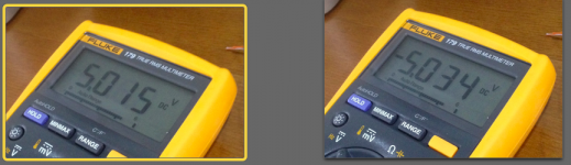
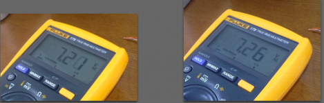
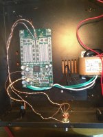
I suspected that the Voltage of 2 rail slightly different (5.015 and -5.034), is this could be a problem? I took several photos at the AC input and the DC supply to resistor rails.
Another thing could be problem is wrong wire to the toshlink receiver, could be?
Any help please?
Thanks!
I start with the most simple way: Toshlink from AirportExpress. But I can not get lock to the signal, the led keep blinking and there is no sound yet.
I suspected that the Voltage of 2 rail slightly different (5.015 and -5.034), is this could be a problem? I took several photos at the AC input and the DC supply to resistor rails.
Another thing could be problem is wrong wire to the toshlink receiver, could be?
Any help please?
Thanks!
Attachments
Last edited:
Hi laptopav,
which type of AirportExpress do you use?
I had problems with the latest incarnation of the AE. The audio stream was so jittery that the WM8004 of the Subbu DAC wasn't able to lock on it. I have not tried this with the DAM DAC though.
Br
Jo
Really? I tried with the N version, 2012 I think.
Update: I just tried with AppleTV, different sample rate with several song but result still the same. And this AppleTV work fine with NAD DAC
Last edited:
Finanly I got all the part and start to solder and get everthing together now.
I start with the most simple way: Toshlink from AirportExpress. But I can not get lock to the signal, the led keep blinking and there is no sound yet.
I suspected that the Voltage of 2 rail slightly different (5.015 and -5.034), is this could be a problem? I took several photos at the AC input and the DC supply to resistor rails.
Another thing could be problem is wrong wire to the toshlink receiver, could be?
Any help please?
Thanks!
Saw you directly pluged a 9V AC R-Core !!!! Dangerous... hope your main 220 AC has not too much fluctuation !
Last edited:
Is there, or will there be, the posibility to use filters which do the filtering to 2.8/3.1 Msps in one step?
At least for reference purpose I would e.g. like to have the best aproximation to the standard textbook reconstruction filter which is possible with 2.8/3.1 Msps, 28 bit.
Not that practical, would require > 3000 taps, and the intermediate frequency is good to have for the CD de-emphasis and crossover filters.
I have choosen 352K/384K as a good compromise for the intermediate rate, so there is space for enough IIR filters for crossover use and room correction. If you go up you get less IIR filters. # filters = 45M/49M divided with intermediate rate divided with 8 = 16.
The FIR2 filter don't require much, I'm looking into doing a bessel or butterworth type filter there.
I think I found the problem, I using the optical receiver Toshiba TORX179 which is required Vcc around 5.0 VDC, so 3.3 VDC now is not enough...
Thought I already order two Toshiba TORX147L from eBay, but in the meanwhile can I take 5.0 VDC supply from dam1021 (J2) or I have to use external power supply or should I wait for eBay (will arrive next month :-()
Thanks.
Thought I already order two Toshiba TORX147L from eBay, but in the meanwhile can I take 5.0 VDC supply from dam1021 (J2) or I have to use external power supply or should I wait for eBay (will arrive next month :-()
Thanks.
I think I found the problem, I using the optical receiver Toshiba TORX179 which is required Vcc around 5.0 VDC, so 3.3 VDC now is not enough...
Thought I already order two Toshiba TORX147L from eBay, but in the meanwhile can I take 5.0 VDC supply from dam1021 (J2) or I have to use external power supply or should I wait for eBay (will arrive next month :-()
Thanks.
You can take 5V from the dam1021, but as the input lines to the dam1021 are 3.3V only you need to divide down the output voltage from the toslink receiver. Looking at the datasheet it have a IOH current of 1 mA, so maybe it's some king of OC already ? Try loading the output down with a 2.2K resistor first....
Soekris,
The following is from correspondence with TEXAS COMPONENTS.
I just ordered some resistors and asked them to explain what they do there which turns out to be what I thought they did and you felt otherwise.
Not to be contentious but credit is due where it belongs.
"We are the original creators of the famous TX2575 audio Foil resistor, and it is manufactured here at our facility in Houston, Texas. We are an authorized Vishay Precision Center for the Bulk Metal® Foil high precision resistors. We get the raw material from Vishay and handcraft the resistors to the requirements and specifications needed by our customers."
Maybe that could be considered value-added just as the way turning sheet metal into an automobile is also a value added process though some might consider this manufacturing.
Hoping to get my board working this weekend. Looking forward to the improved filters. Thanks for the product and the work you have put into it.
- Home
- Vendor's Bazaar
- Reference DAC Module - Discrete R-2R Sign Magnitude 24 bit 384 KHz