Not all polymers are the same. I recommended the Nichicon FP they are the best that sounded in several projects that I did, for several witnesses and friends. In some rare cases other electrol.caps can give better results. Of course PP is another step but the low values...after detail listening sessions, in my particular case and in the analogue part of DAC [plz look on the former report], polymer caps gave me decreasing of tonal balance and muddy air... and PP caps improvements only. For sure an amount of PP caps is not enough often and you have to compensate it through another cap types..
 Maybe the FP is the second best?
Next step, I'll still mix some different valued PP with the polymer, inspired by the reactance nulling from my friend Maurício.
For SMD soldering I use a microscope which makes it very easy
Not too expensive. If I thought I would be doing more of this I would get one.
Still I wonder if I could do it.
Thanks for the recommendation, nonetheless.
On another subject:
I would think there would be some interest in removing the feedback cap from the board and making the path shorter by connecting the - in and output pins with a length of silver wire. Easy and better, I would think.
More thoughts about the output resistor and the added capacitance regarding the peaking - if the DAC came equipped with a 10R output resistor and 47 uF of capacitance and we lower the resistor to .1R and 470 uF we raise the filter to 3386 hz from 338 - if we use, say HIFIDUINO's approach we arrive at 301 hz - so one, and in this case one who has all of the abilities of the dilettante, wonders: what is the important thing here? Is it the output resistor's value or the frequency of the filter?
10R & 47 uF - 338 Hz
.1R & 94 uF - 16.9 kHz
.1R & 470 uF - 3386 Hz
.1R & 5280 uF - 301 Hz
.4R & 16000 uF - 24.8 Hz - picked a value I have on hand for R and using 16 1000 uF caps
Well, it doesn't look like the pole has much to do with it based upon SOEKRIS's recommendation. Should one keep the pole above the 12kHz peak?
Can the pole be too low? As Paul @ moreDAMfilters has asked on his blog could R be too low? Is the value of R the most important thing? More important than the pole of the filter?
Not wanting to have to do this again (since I cannot do it myself) I would like to be sure (well, as sure as we can ever be about such things) before proceeding.
Eeeh, using my recommendation in post #3108 there will no peaking.... Adding more capacitance will only improve, but at some point the improvements will not be noticeable....
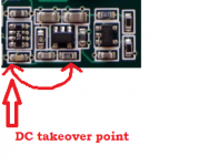
The idea is that the opamp via the small series resistors keep the impedance low until the capacitor take over.
The idea is that the opamp via the small series resistors keep the impedance low until the capacitor take over.
.4R & 16000 uF - 24.8 Hz - picked a value I have on hand for R and using 16 1000 uF caps
Rickmcinnis,
The combination 0.4ohm and 4V giving us a cap charge rate around 10 A. Using a capacitor of 16000uF it is also long enough for something hot. Of course, I understand that an opamp has a current limit, but this is clearly not the appropriate energy level for our device.
Last edited:
Before modding I first did some measurements of the current configuration (plus some additional bypass capacity). Which lead to a remark and a request:
Firstly, it is possible to measure vref with a sound card if it supports Pro audio levels or is AC cupeled (I however take no responsibility for fried cards).
This gives you, in the audio frequency range, much more detailed information compared to the mV you get from a scope.
For example here the Vref with a white noise signal (fs=384kHz) with additional 1000uF (red) compared to the stock configuration (green).

Secondly a request to someone with a fast scope to verify the following measurements (my scope is getting old and I do not trust it entirely when pushed to the limits).
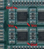
The measurements were made between ground- and Vcc-pin of the MSB shift register. Measuring Vref somewhere else works too but the "signal" is weaker.
I measured a 96kHz sine recorded with fs=384 kHz and the NOS filter (this does not realy matter, at least for the two last pictures) without applying the bandwidth limiter of the scope. And I see peeks of 100-200 mV magnitude but oscillating fast.

Zooming in, shows that the main oscillation pattern repeats (twice?) with the shift register clock input (upper signal, ~24.5MHz, in second picture) but has a faster oscillation of ~ 4nS or 250MHz.


Putting a fast capacitor (Wima FKP, Mica) over the ground- and Vcc-pin tames the magnitude but the signal is still there.
The big bypass capacitor has no influence on this signal. The fast capacitor has no influence in the audio range.
Firstly, it is possible to measure vref with a sound card if it supports Pro audio levels or is AC cupeled (I however take no responsibility for fried cards).
This gives you, in the audio frequency range, much more detailed information compared to the mV you get from a scope.
For example here the Vref with a white noise signal (fs=384kHz) with additional 1000uF (red) compared to the stock configuration (green).
Secondly a request to someone with a fast scope to verify the following measurements (my scope is getting old and I do not trust it entirely when pushed to the limits).
The measurements were made between ground- and Vcc-pin of the MSB shift register. Measuring Vref somewhere else works too but the "signal" is weaker.
I measured a 96kHz sine recorded with fs=384 kHz and the NOS filter (this does not realy matter, at least for the two last pictures) without applying the bandwidth limiter of the scope. And I see peeks of 100-200 mV magnitude but oscillating fast.
Zooming in, shows that the main oscillation pattern repeats (twice?) with the shift register clock input (upper signal, ~24.5MHz, in second picture) but has a faster oscillation of ~ 4nS or 250MHz.
Putting a fast capacitor (Wima FKP, Mica) over the ground- and Vcc-pin tames the magnitude but the signal is still there.
The big bypass capacitor has no influence on this signal. The fast capacitor has no influence in the audio range.
Rickmcinnis,
The combination 0.4ohm and 4V giving us a cap charge rate around 10 A. Using a capacitor of 16000uF it is also long enough for something hot. Of course, I understand that an opamp has a current limit, but this is clearly not the appropriate energy level for our device.
Thanks, alecm,
Trying to find out where the boundaries are.
Have you come to a conclusion of what the optimum amount of capacitance would be?
I was not sure if all of the shift register's bypass caps are in parallel or just feeding the individual shift registers. I did wonder if that might put quite a strain on the regulator at start up if they were. And I do not know if that would make any difference, anyway. Haven't done anything yet.
Bought 0.1R resistors with the conductive strip going in the wrong direction! Had to order the correct ones. So now I have removed the components and will have to wait until the correct resistors arrive on Tuesday to finish this.
Do you have an opinion on HIFIDUINO's idea of caps at each shift register? Seems like a good idea to me not having to have the extra caps stacked at the regulator. "Good practice" seems to be to have the capacitance at the load instead of at the output of the regulator so this seems to be the best way.
Now if I could figure out what would be the best capacitors to use.
There are those who think the polymers are suspect in the "analogue" part of a DAC and I have no idea if a shift register could be construed as being analogue in any way even though it is directing the resistor stack which does seem to be "analogue". So I wonder if one should use a conventional "audio" cap there - like the SILMICS or any of the other highly regarded electrolytics recommended for use in power supplies for analogue circuits.
Needless to say, your opinion would be welcomed!
One thing after another ...
After posting I see zfe's post - very interesting but discouraging. I guess perfection will not be achieved? Bittersweet realization. Again!
Last edited:
Zooming in, shows that the main oscillation pattern repeats (twice?) with the shift register clock input (upper signal, ~24.5MHz, in second picture) but has a faster oscillation of ~ 4nS or 250MHz.
thanks for real catch! I have fq limitation of my oscilloscope and not saw it.
Now we going to the dark hole area where chip leg length has a big matter. Unfortunately, sizes of dam1021 components are big and not suitable for such fq.s and resolving problems in Mhz area are raising many other problems underway.
i have proposition to mod this. this is not ideal approach but...
resistor ladder drawing current around 5mA. So, try to connect the 3 kOhm resistor to the legs of Vcc-Gnd. possibly it will decrease the oscillation. please see the attachment.
Attachments
Have you come to a conclusion of what the optimum amount of capacitance would be?
now i working on several new mods and waiting for certain results. I wouldn’t recommend you the optimum amount of capacitance.
i will get back later with my ideas on this...
now i working on several new mods and waiting for certain results. I wouldn’t recommend you the optimum amount of capacitance.
i will get back later with my ideas on this...
Thanks again most intrepid one!
I also wonder when one is paralleling multiple caps - can ESR get too low?
I continue to like the idea of multiple higher capacity caps at each shift register but wonder if we should consider using something other then ultra low ESR caps? Of course, I then remind myself that they are already bypassed by MLCCs but their low impedance becomes meaningless at anything other than very high frequencies.
Can't wait to see (and hear) what you come up with.
make sure to read "LATE NOTE" at end of my post
Tomorrow I'll have time to play with the DAM, I'll complete some measurements as suggested by alecm but inspired in zfe measurements. As I already make my DAM mods, and I'm not willing to undo (if I forget to save some, I don't redo). With oscilloscope, probably I don't need publish... see that zfe here shows a huge ripple, more than in my own original measurements, and my mod result I no longer detect the ripple with my oscilloscope; It is well below 5 mV. So, you might just find that I turned off the oscilloscope input to impress, but it's true, try for yourself and see if in doubt.
I've realized the FFT in 4V line, with interesting results. I hope I have saved the before and the after ... I tend to be very disorganized in my DIY measurements saving tasks... When I return to the lab/home, I publish some measurements (finally).
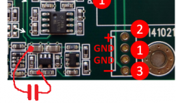
LATE NOTE: I noticed that the return of original feedback 4V supply resistor in DAM comes a point after one of the shift registers, which makes the opamp amplify the noise that it induces, like an remote DC sensing. Maybe the ceramic cap is barely working here... My 47μF capacitor mod takes the signal direct from the "official" output of the regulator, totally bypassing the noise becoming from the "680" resistor, and this prevents undesirable voltage drops that can be amplified by the supply. I suspect this is what caused the biggest difference, because to me made no sense THAT huge ripple size with such low drain circuit like this . Soon I'll get some pictures of the DAM and try to explain my suspicion.
Before modding I first did some measurements of the current configuration (plus some additional bypass capacity). Which lead to a remark and a request:
Firstly, it is possible to measure vref with a sound card if it supports Pro audio levels or is AC cupeled (I however take no responsibility for fried cards).
This gives you, in the audio frequency range, much more detailed information compared to the mV you get from a scope.
For example here the Vref with a white noise signal (fs=384kHz) with additional 1000uF (red) compared to the stock configuration (green).
View attachment 495514
Secondly a request to someone with a fast scope to verify the following measurements (my scope is getting old and I do not trust it entirely when pushed to the limits).
The measurements were made between ground- and Vcc-pin of the MSB shift register. Measuring Vref somewhere else works too but the "signal" is weaker.
I measured a 96kHz sine recorded with fs=384 kHz and the NOS filter (this does not realy matter, at least for the two last pictures) without applying the bandwidth limiter of the scope. And I see peeks of 100-200 mV magnitude but oscillating fast.
View attachment 495515
Zooming in, shows that the main oscillation pattern repeats (twice?) with the shift register clock input (upper signal, ~24.5MHz, in second picture) but has a faster oscillation of ~ 4nS or 250MHz.
View attachment 495516 View attachment 495517
Putting a fast capacitor (Wima FKP, Mica) over the ground- and Vcc-pin tames the magnitude but the signal is still there.
The big bypass capacitor has no influence on this signal. The fast capacitor has no influence in the audio range.
Tomorrow I'll have time to play with the DAM, I'll complete some measurements as suggested by alecm but inspired in zfe measurements. As I already make my DAM mods, and I'm not willing to undo (if I forget to save some, I don't redo). With oscilloscope, probably I don't need publish... see that zfe here shows a huge ripple, more than in my own original measurements, and my mod result I no longer detect the ripple with my oscilloscope; It is well below 5 mV. So, you might just find that I turned off the oscilloscope input to impress, but it's true, try for yourself and see if in doubt.
I've realized the FFT in 4V line, with interesting results. I hope I have saved the before and the after ... I tend to be very disorganized in my DIY measurements saving tasks... When I return to the lab/home, I publish some measurements (finally).
LATE NOTE: I noticed that the return of original feedback 4V supply resistor in DAM comes a point after one of the shift registers, which makes the opamp amplify the noise that it induces, like an remote DC sensing. Maybe the ceramic cap is barely working here... My 47μF capacitor mod takes the signal direct from the "official" output of the regulator, totally bypassing the noise becoming from the "680" resistor, and this prevents undesirable voltage drops that can be amplified by the supply. I suspect this is what caused the biggest difference, because to me made no sense THAT huge ripple size with such low drain circuit like this
. Soon I'll get some pictures of the DAM and try to explain my suspicion.
Last edited:
Figures:
DAMexp4 is my "suspicious" (buffer contamination)
DAMexp3 is my actual 47µF mod
Is the not most correct mod but helps to explain some things
The Soekris mod also make the "680" res inoperative with low impedance jumpers in cap position so will have even better results, probably...
DAMexp4 is my "suspicious" (buffer contamination)
DAMexp3 is my actual 47µF mod
Is the not most correct mod but helps to explain some things
The Soekris mod also make the "680" res inoperative with low impedance jumpers in cap position so will have even better results, probably...
Attachments
Some "sound-card measurements" of Vref (4Vpp would be -7.5dBFS).
First, to compare, Vref when playing white noise in the stock config (green) and stock plus 1000uF (red).

Next the "factory mod" and variants:
The red curve is Vref when playing white noise, the green one (if nothing else said) Vref when no signal played (which coincides more or less with the noise floor).
1. a) factory mod, b) factory mod +1000uF, c) factory mod +6800uF (over 1000uF green), d) factory mod +17000uF (over 6800uF green)


2. A variant of the factory mod using 1 Ohm as load resistor instead 0.1 Ohm
a) 1 Ohm factory mod, b) 1 Ohm factory mod +1000uF, c) 1 Ohm factory mod +6800uF


P.S. the high frequency behavior on the oscilloscope does not changed due to the factory mod. But as I said, I am mot sure if this not an problem of my oscilloscope. The high frequency behavior needs to be verified by independent measurements.
First, to compare, Vref when playing white noise in the stock config (green) and stock plus 1000uF (red).
Next the "factory mod" and variants:
The red curve is Vref when playing white noise, the green one (if nothing else said) Vref when no signal played (which coincides more or less with the noise floor).
1. a) factory mod, b) factory mod +1000uF, c) factory mod +6800uF (over 1000uF green), d) factory mod +17000uF (over 6800uF green)
2. A variant of the factory mod using 1 Ohm as load resistor instead 0.1 Ohm
a) 1 Ohm factory mod, b) 1 Ohm factory mod +1000uF, c) 1 Ohm factory mod +6800uF
P.S. the high frequency behavior on the oscilloscope does not changed due to the factory mod. But as I said, I am mot sure if this not an problem of my oscilloscope. The high frequency behavior needs to be verified by independent measurements.
And "sound-card measurements" of Vref with a 1kHz signal playing:
First a) stock (red) over no signal (green), b ) stock+1000uF (red) over stock (green), c) stock+6800uF (red) over stock+1000uF (green)


Then a) factory mod (red) over no signal (green), b) factory mod+1000uF (red) over factory mod (green), c) factory mod+6800uF (red) over factory mod+1000uF (green), d) factory mod+17000uF (red) over factory mod+6800uF (green)


First a) stock (red) over no signal (green), b ) stock+1000uF (red) over stock (green), c) stock+6800uF (red) over stock+1000uF (green)
Then a) factory mod (red) over no signal (green), b) factory mod+1000uF (red) over factory mod (green), c) factory mod+6800uF (red) over factory mod+1000uF (green), d) factory mod+17000uF (red) over factory mod+6800uF (green)
And "sound-card measurements" of Vref with a 1kHz signal playing:
many thanks for inputs!
You giving us lots of food for reflection.

Please try to check the interchannel crosstalk - send a signal to one channel and check spectral recording in the different one
Thanks, alecm,
Trying to find out where the boundaries are.
Have you come to a conclusion of what the optimum amount of capacitance would be?
I was not sure if all of the shift register's bypass caps are in parallel or just feeding the individual shift registers. I did wonder if that might put quite a strain on the regulator at start up if they were. And I do not know if that would make any difference, anyway. Haven't done anything yet.
Bought 0.1R resistors with the conductive strip going in the wrong direction! Had to order the correct ones. So now I have removed the components and will have to wait until the correct resistors arrive on Tuesday to finish this.
Do you have an opinion on HIFIDUINO's idea of caps at each shift register? Seems like a good idea to me not having to have the extra caps stacked at the regulator. "Good practice" seems to be to have the capacitance at the load instead of at the output of the regulator so this seems to be the best way.
Now if I could figure out what would be the best capacitors to use.
There are those who think the polymers are suspect in the "analogue" part of a DAC and I have no idea if a shift register could be construed as being analogue in any way even though it is directing the resistor stack which does seem to be "analogue". So I wonder if one should use a conventional "audio" cap there - like the SILMICS or any of the other highly regarded electrolytics recommended for use in power supplies for analogue circuits.
Needless to say, your opinion would be welcomed!
One thing after another ...
After posting I see zfe's post - very interesting but discouraging. I guess perfection will not be achieved? Bittersweet realization. Again!
silmics have very distinct signature like very rounded sound and unless and untill the system is very harsh silmics sound blurred and lost attack and resolution even after 500hours of burning.
As a decoupling caps in my experience over the past 3 years i never found silmic sound with great resolution and in fact its overly rounded sound even wit mix and match wit nichicon FG or muse they still sound artificial.
And "sound-card measurements" of Vref with a 1kHz signal playing:
First a) stock (red) over no signal (green), b ) stock+1000uF (red) over stock (green), c) stock+6800uF (red) over stock+1000uF (green)
View attachment 495821 View attachment 495822 View attachment 495823
Then a) factory mod (red) over no signal (green), b) factory mod+1000uF (red) over factory mod (green), c) factory mod+6800uF (red) over factory mod+1000uF (green), d) factory mod+17000uF (red) over factory mod+6800uF (green)
View attachment 495824 View attachment 495825 View attachment 495826 View attachment 495827
why there is a strong peak of 50Hz?
- Home
- Vendor's Bazaar
- Reference DAC Module - Discrete R-2R Sign Magnitude 24 bit 384 KHz