I selected caps with 3.5mm lead spacing, cut leads to comfortable length (could be shorter...)
Then made sure polarity orientation was correct and bent leads 90 degrees for 1 to 1.5mm such that they aim away from opamp.
Then narrowed them slightly so that the snugly fit over SMD cap and would free stand without my having to hold them.
Then I pre-tinned cap "feet" and put them back in position.
Heating one side while holding the cap down, allowing to cool completely before heating the other side.
Technically paralleling two capacitors one large with one small wouldnt that create poles?
Is it recommended to remove the ceramic cap on the board and use the large cap?
Could somebody who has updated their filters using a Linux machine post how they went about it? Had no luck with cu, cutecom or extraputty under wine.
Use minicom as root user.
Regards,
Tibi
Finally I tried adding the Polymer caps SEP 56uf / 10V and the sound is coming out of the speakers than sticking to it. Yes indeed its a decent improvement. You need to listen to various tracks to identify this effect as by default the sound quality is soo high that checking this took a min for me. Ill try using 470uf next time.
Heating one side while holding the cap down, allowing to cool completely before heating the other side.
Did the same thing, initially burned (large tip, 330 deg) the marked caps on Soren's picture. Then went on with 250 deg and smaller tip and burned the ones next to them. These are also between 4v, but i don't know what becomes after those.
I'm a noob in smd stuff. Are those ceramics there, not tantalums (couldn't find polarity)?
Anyways, interesting bit is, w/o these original caps sound is noticeably harsher and sharper in treble.
In the end i scrapped some 24u ceramics from an old mobo and added some random 470u electrolytes on the 4v vref rail.
Definently big leap ahead in sound. Next stop some larger value ceramics/ tantalums + some oscons.
Could somebody who has updated their filters using a Linux machine post how they went about it? Had no luck with cu, cutecom or extraputty under wine.
Use Python dam1021 library. Then, considering you are in the library directory, issue the following:
$ python dam1021.py -s /dev/ttyS0 -d 1021filt_EQHQ_V2r1.skr
That's all.
btw. you as a system user must have r/w access to a serial device.
New hifiduino update which explains the cap mod, great attention to detail, however I question the requirement of 16 caps for bypassing each shift register.")
Need to try this
Use Python dam1021 library. Then, considering you are in the library directory, issue the following:
$ python dam1021.py -s /dev/ttyS0 -d 1021filt_EQHQ_V2r1.skr
That's all.
btw. you as a system user must have r/w access to a serial device.
Thank you.
New hifiduino update which explains the cap mod, great attention to detail, however I question the requirement of 16 caps for bypassing each shift register.
Not a requirement, just for fun and for looks
Which one?

As far as i understand, put 4 cap on four main capacitors on the vref lines (Soren and suggestion) is the same effect with put 8 cap on each shift registers (glt suggestion)?
Or we have to do both?
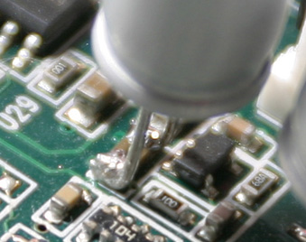
To make it easier to add capacitors to the vref supplies I added some markings to the dam1021 photo.
The red markings are the four main capacitors on the vref lines, the green plus is the polarity.
Note that polarized electrolytic capacitors need to be mounted correctly and they need to have very low esr, less than 50 mOhm, around 20 mOhm would be really good and that usually mean polymers.
Ceramics capacitors are not polarized and have very low esr, so those I will recommend, 1-2 pcs 47uF X5R 6V3 0805 added to each rail will make a large difference in noise/ripple on the vref rails.
Personally I don't believe that removing the op-amp load should make any difference, there I agree with rickmcinnis about own perceptions....
As far as i understand, put 4 cap on four main capacitors on the vref lines (Soren and suggestion) is the same effect with put 8 cap on each shift registers (glt suggestion)?
Or we have to do both?
Not a requirement, just for fun and for looks
Haha indeed it looks good, and sure to fullfill all bypass requirements. I'm so tempted to try this as well. Such clever use of existing via's.
EDIT: More oscon's on the way. sigh.
Last edited:
Poles? At least one pole with one cap.Technically paralleling two capacitors one large with one small wouldnt that create poles?
Is it recommended to remove the ceramic cap on the board and use the large cap?
An friend of mine bypass with an decade of capacitors to make a lot of poles*** and to lower the total RF/HF impedance, since every cap has an "valley" where Z is low (point of zero reactance). He names it "reactance nulling". The results are very good to my ears so maybe I try it in some project with room to that... Some professional RF workers also recommend to use several values of C to supress supply RF resonances.
***he uses more or less (for amp): 560pF - 10nF - 47nF - 150nF - 1µF - 22µF - 470µF - 1000µF all in // parallel near the "victim". At least he makes some harsh sounding sand amps sounding far better after using this method at power supply.
Not a requirement, just for fun and for looks
Very neat job GLT!
Hmmm ... I probably ended up mixing the issues that are related. Poles on power supplies are influenced by the output capacitors and can oscillate depending on the type, so I mentioned this idea of multi-capacitors to cancel/reduce the reactance (in many supplies this works well).wouldn't you need a resistor between caps to get a pole?
In any case, we also consider the circuit consumption as a "resistor" to the source (or current source in other cases).
Anyway, I don't make this in DAM since I don't see need for that outragerous "reactance-nulling" decoupling here.
Last edited:
When can we expect a new firmware? The inverted volume control spots are annoying.
In a few days, just finishing up the code....
- Home
- Vendor's Bazaar
- Reference DAC Module - Discrete R-2R Sign Magnitude 24 bit 384 KHz