Alecm, very nice work with the r2r noise issue. I added some polymer caps to the shift register rails. Very nice outcome!
Very good. Waiting for pics and detail sound outcomes.
")
56uf. That's all I had at hand. I need to order some 1X scope probes to measure the outcome...
220uf is not freakish hit. Initially, I have added the 4.7uf film cap, not enough. 33uf polymer later and not enough as well. and finally set the 220uf and have received the good wave on the oscilloscope.
OK thanks. Understood. Are your transistors inside the opamp feedback loop? If so you should not lose 0.6v?
Here transistor is out of feedback. It's an idea, otherwise we have the same problems with phase margin shift and oscillation.
Last edited:
A Couple of notes:
1) The vref buffer design are unconditional stable with large capacitance, so you can hang on as much as you want, but 220uF to 470 uF low esr / polymer on each of the four vref supplies is a good choice.
2) It's unnecessary to add multiple smaller capacitors as the PCB have power planes with smaller ceramics at each '595.
3) You can also get 47uF X5R 6V3 ceramics in 0805 size, easy to stack on top of existing capacitors....
4) Please don't try external vref supplies, they're not needed and the risk to ruin your board is great.
The vref power supplies is something that I'm already looking at for next rev, will advise recommended modifications when I'm ready....
56uf. That's all I had at hand. I need to order some 1X scope probes to measure the outcome...
A Couple of notes:
1) The vref buffer design are unconditional stable with large capacitance, so you can hang on as much as you want, but 220uF to 470 uF low esr / polymer on each of the four vref supplies is a good choice.
...
The vref power supplies is something that I'm already looking at for next rev, will advise recommended modifications when I'm ready....
Thanks Soren and Paul for chiming in. Will try with the 1,000uFs I have around and look forward to future recommended mods
I received my DAM last week. I've done an update in the digital filter, as it is one of the features that made me interested in DAM project (and direct ladder output is a must!). Using ExtraPutty (with DIYA member DimDim tips), was a success.The sound is different now, seems to be less "electronic", but I need more time to better evaluate (EQHQ filter).
I'm still using only one basic transformer in the power input, and I think in doing all the sucessfull upgrades proposed by Alecm and some others, specially mod#2; mod#3 I already made. I have oscilloscope and FFT analyzer (and ears!) to enjoy myself the results.
There are some small oddities in FFT analysis that I believe should disappear with the upgrade proposed by Alecm, since the voltage at the R-2R is completely proportional to the 4V supply, and any change in this will pass directly/proportionally to the audio output. These small oddities not change with changing filter, so is not becoming from digital filter section, and remember somewhat the output from old Sanyo LC7881 IC DAC (an "mixed-format" CMOS DAC: ladder+simple voltage divider+PWM).
Congratulations Soekris by radical initiative of a discrete DAC R-2R!
Importance of DAC output
99,95% of opamps will cry to that RF crud.
My experience with DAC outputs started years ago with an el-cheapo DVD, with 1V HF crud 1-bit "integrated" DAC using an 1V/µs RC4558... , soooo stupid for filtering that. The output from 4558 is only a distorted HF from input... After changing this to an RC filtering, the sound becomes decent.
The DAM generates almost zero HF crud in comparision, since DAM is a true PCM DAC...
My experience, too: even the CS4398 have an great sound if you make an decent passive filter and exclude every op-amps from sigh. The CS4398 make HUGE HUGE RF output, with almost 100mV on certain HF freqs!!!Interesting, assuming to remove op-amps from cheap Chinese brand DAC to use the raw outputs would bring it to the same quality level.
It's a shame that this DAC failed on analog section as usually happens to digital guys.
99,95% of opamps will cry to that RF crud.My experience with DAC outputs started years ago with an el-cheapo DVD, with 1V HF crud 1-bit "integrated" DAC using an 1V/µs RC4558...
, soooo stupid for filtering that. The output from 4558 is only a distorted HF from input... After changing this to an RC filtering, the sound becomes decent.The DAM generates almost zero HF crud in comparision
, since DAM is a true PCM DAC...Outcome
The mod#1 result is not auditioned in details. But the results in sound of last two mods are amazing in some areas. The most significant improvements are:
- Very deep soundstage (mod#2) outward room bounds with good localization (mod#3).
- The loudspeakers are dissolved in the room (both mod#2 and #3)
- Tremendously increased sound dynamics (both mod#2 and #3)
- Significant increased resolution and detailization (both mod#2 and #3, but especially mod#2)
Very nice work Alec !
I've added some polymers to my shopping list
Does this 4 cap mod change anything regarding the power-off "plop"?
partly yes it does but not fully..
hi, comickitkit,
this is the very interesting point.
IMHO, to receive the maximum result you have to remove it anyway. But implementing mod#3 only will not help you enough. The good result I have received to combine both of it. And this is the key. When i have done the mod#2 and still not have done #3, i received the bad result in stage and localization point of view. The sound looked like out of phase. The mod#3 fully resolved it.
Prior your findings I removed whole balanced sections and I would describe the outcome in a similar fashion. Great soundstage, improved dynamics. It is hard to believe this could be improved even further thanks to the mod#2. But then this DAC redefines limits of my off the shelf components (pretty old creek4330 amp and equally old some entry-level avance speakers) so I probably should shut up and wait patiently for caps delivery. It would be also interesting to verify your attribution model since I'm going to reproduce your efforts, but in a reverse order.
btw. I find it that proper speaker placement is a way more crucial to qualities of sound reproduction your mods deal with. In my setup Joachim Gerhard approach works the best. I'm quite conservative with other tweaks. Only mravlca TPS7A4700 low noise LDO regulators in front of DAC power lines. And EQHQ_v2r1 filter.
Thanks for your effort.
Last edited:
Dear alecm,
You certainly have excited this thread with your mods.
When I removed the balanced output opamps I thought I was hearing an improvement but thought it was something between wacky audiophile dreaming and the corollary to BARANEKS LAW, the one about how nothing sounds better than the loudspeaker you made - any mod one does to a component sounds good to the one who made the change. Nothing like having one's perceptions verified.
Can't wait to add the caps.
Any opinion on whether the polymers are superior to the ceramics in this position? SOEKRIS's idea of stacking the ceramics would make for a neat install in comparison if they would give the equivalent result.
Have you considered using your 5 volts regs at the input of the DAC - not sure if those regs are strong enough to power the 3.3 reg so have you considered using the same regulator you used (for 5 volts) as a replacement of the 3.3 v as supplied on the board?
Nothing better than having measured proof when such proof correlates with what you are hearing!
THANKS very much for your explorations
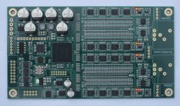
To make it easier to add capacitors to the vref supplies I added some markings to the dam1021 photo.
The red markings are the four main capacitors on the vref lines, the green plus is the polarity.
Note that polarized electrolytic capacitors need to be mounted correctly and they need to have very low esr, less than 50 mOhm, around 20 mOhm would be really good and that usually mean polymers.
Ceramics capacitors are not polarized and have very low esr, so those I will recommend, 1-2 pcs 47uF X5R 6V3 0805 added to each rail will make a large difference in noise/ripple on the vref rails.
Personally I don't believe that removing the op-amp load should make any difference, there I agree with rickmcinnis about own perceptions....
Attachments
Last edited:
To make it easier to add capacitors to the vref supplies I added some markings to the dam1021 photo.
The red markings are the four main capacitors on the vref lines, the green plus is the polarity.
Note that polarized electrolytic capacitors need to be mounted correctly and they need to have very low esr, less than 50 mOhm, around 20 mOhm would be really good and that usually mean polymers.
Ceramics capacitors are not polarized and have very low esr, so those I will recommend, 1-2 pcs 47uF X5R 6V3 0805 added to each rail will make a large difference in noise/ripple on the vref rails.
Personally I don't believe that removing the op-amp load should make any difference, there I agree with rickmcinnis about own perceptions....
Hi soren few points to consider
Let the board size gets a little bigger like a centimeter on x and y axis more but do make some excellent power supplies.
After seeing the graphs of outputs Im just shocked that how was the design published. I mean that 10 ohm resistor making problem.
Why dont you consider a discrete shunt regulator? simpler one or use one of the LT regs with noise less than 1uV but still not sufficient for the R2R ladder I feel.
But soren Caps use great caps and have an isolated power supply for the balanced output stage so that the R2R doesnt get loaded up.
470uF / 6.3V SEP 15 mohm would work fine? for the capacitor mod?
I have 56uf / 10V SEP 45mohm would that be ok?
Can't wait to add the caps.
Dear Rick,
it seems like both mods (#2 and #3) are multiplying (not add) the result of each others. Hope adding the caps only will help to avoid bad oscillations and give you the good results.
Any opinion on whether the polymers are superior to the ceramics in this position?
Please see http://industrial.panasonic.com/lecs/www-data/pdf/AAB8000/AAB8000PE24.pdf, for example. Page 3.
Have you considered using your 5 volts regs at the input of the DAC - not sure if those regs are strong enough to power the 3.3 reg so have you considered using the same regulator you used (for 5 volts) as a replacement of the 3.3 v as supplied on the board?
Yes, i have a plan to exchange the original ZLDO1117 on very low noise one.
https://drive.google.com/file/d/0B4JU1DLmHzHsaklCMDl6bWFuNmM/edit
I like this one very much.But here I have close to Soren's opinion on achievements and not waiting for the same level of progress in comparison to mod 2-3.
Last edited:
With a DAC output that is so sensitive to load a buffer seems to be all the more important to me.
I want to build a serious multichannel studio DAC, so balanced outputs capable of driving different loads are mandatory.
Is there a way to change the output buffer and balancing stage so it does not affect the DAC output (if it is indeed true that it does)? Maybe an inverting op amp buffer? At least there will be a resistor between the buffer and the DAC output this way...
Soren, thanks
A transistor base is easy load for any opamps and you have free hands to increase capacitor values without any fears to become unstable, leading to oscillation.
For sure, there is very interesting to try caps in parallel (bypass). possibly someone try it as well and will share his exp.
My idea was not using large values but ESR cap parameters more.
Wow, thats really cool work Alecm! I have a question towards the 10 Ohm resistor which is making noise. Is it the current noise of this resistor that makes such distortion? If yes, I think we can just change it with low noise resistors, e.g. Vishay high precisions or simply some good wire wound resistors. The high inductance of wire wounds may also help to filter out the noise IMO.
With a DAC output that is so sensitive to load a buffer seems to be all the more important to me.
I want to build a serious multichannel studio DAC, so balanced outputs capable of driving different loads are mandatory.
Is there a way to change the output buffer and balancing stage so it does not affect the DAC output (if it is indeed true that it does)? Maybe an inverting op amp buffer? At least there will be a resistor between the buffer and the DAC output this way...
According to the description from Alecm, I think supplying the OP amps separately will be a easy choice
I hate to put on dampener on the great work Alecm did finding the noise of the vref buffer outputs but a transistor junction in series with the reference which is outside the feedback loop is not the solution. This will result in a voltage reduction in the reference of approximate 0.6V but the exact value will be random according to the actual vbe of the device used. Hence all the good work done by the circuity to this point to keep both +/- rails exactly the same will be undone and additional distortion will be end result.
I agree with Soren that the main source of this temporary fix is the 220uf capacitor and not the transistor.
I agree with Soren that the main source of this temporary fix is the 220uf capacitor and not the transistor.
Last edited:
Dear alaecm,
The PANASONIC data sheet is interesting as all of them are. As with most of them what makes them most interesting is how they compare things.
First off, I am not a fan of ceramic caps being an aging audiophile who was taught from an early age to fear the ceramic as the werewolf the silver bullet yet it would seem that PANASONIC would have used like capacity in their comparisons. The OSCONs are twice as large and would easily display lower ESR.
Even if the comparison used like values the aspect of stacking the ceramics allows for easily adding additional capacitance for the inevitable variability of the ceramic.
I guess we will just have to find out for ourselves the sonic consequences of each.
I am capable of removing the stock ceramics but I know my limits - I could never get something to stick to those pads afterwards so one way or another I will be using the stock ceramic and tacking a polymer to it which will be easy with that next to impossible to melt solder used for production. The one time in my DIY life that I am grateful for that stuff!
I am hoping there might just be serendipitous value to using both types in this position.
AS far as SOEKRIS incorporating a shunt regulator on the board - this would obviously increase the price dramatically and not all of the folks who will buy this DAC have systems that would notice the difference. I think SOEKRIS made a great many canny choices to bring this DAC to market at such an incredible price. All I would ask for is if there is some way that could make changing onboard supplies easier and that is far from a passionate request. It would be nice but not important.
alecm is the latest intrepid tinkerer to give us insight into how this board can be made even better. Thanks, always, to SOEKRIS without whom we would be playing around with a lesser board but also gratitude to those who have looked closely at the board and had the nerve to change something and tell us about it.
Dear alaecm,
The PANASONIC data sheet is interesting as all of them are. As with most of them what makes them most interesting is how they compare things.
First off, I am not a fan of ceramic caps being an aging audiophile who was taught from an early age to fear the ceramic as the werewolf the silver bullet yet it would seem that PANASONIC would have used like capacity in their comparisons. The OSCONs are twice as large and would easily display lower ESR.
Even if the comparison used like values the aspect of stacking the ceramics allows for easily adding additional capacitance for the inevitable variability of the ceramic.
I guess we will just have to find out for ourselves the sonic consequences of each.
I am capable of removing the stock ceramics but I know my limits - I could never get something to stick to those pads afterwards so one way or another I will be using the stock ceramic and tacking a polymer to it which will be easy with that next to impossible to melt solder used for production. The one time in my DIY life that I am grateful for that stuff!
I am hoping there might just be serendipitous value to using both types in this position.
AS far as SOEKRIS incorporating a shunt regulator on the board - this would obviously increase the price dramatically and not all of the folks who will buy this DAC have systems that would notice the difference. I think SOEKRIS made a great many canny choices to bring this DAC to market at such an incredible price. All I would ask for is if there is some way that could make changing onboard supplies easier and that is far from a passionate request. It would be nice but not important.
alecm is the latest intrepid tinkerer to give us insight into how this board can be made even better. Thanks, always, to SOEKRIS without whom we would be playing around with a lesser board but also gratitude to those who have looked closely at the board and had the nerve to change something and tell us about it.
There already is a shunt regulator on this board. Its used to generate the -4V reference from which the 4V reference is derived.
- Home
- Vendor's Bazaar
- Reference DAC Module - Discrete R-2R Sign Magnitude 24 bit 384 KHz